:stnetnoCkcaP
1x
kcapgnixiF 1x
1xtelfaelnoitcurtsnI
DNANOITALLATSNIGNICNEMMOCEROFEBESEHTDAERESAELP
.ECNEREFERERUTUFROFNIATER
llahsti,egamadsitekcossihtfodrocroelbacelbixelflanretxeehtfI
ralimisrotnegaecivressihrorerutcafunamehtybdecalperylevisulcxeeb
.drazahadiovaotredroninosrepdeifilauq
.htraetsuM.tcudorpIssalCasisihT
ylnoesuroodniroF-kcohScirtcelEfoksiR:NOITUAC
lanretnihtiwstcudorplatigidehtrofelbacilppatonsitI:NOITUAC
emmargorpgnivirdgniriuqersenoehtronoitcetorp
.naicirtceledeifilauqatlusnoc,snoitallatsniesehtgnidragertbuodnifI
NOITALLATSNI
CDV5:egatloVtuptuO
2100mA
.XAM:tnerruCtuptuO
NOITACIFICEPSREGRAHCBSU
NOITCURTSNINOITALLATSNI
:tcudorP
DCS281-2U
ecnadroccanitsilaicepslacirtcelenaybtuodeirracebylnoyamnoitallatsniehT
.sdradnatslanoitandnalanoitanretnihtiw
220-240V~50-60Hz
Max. 13A
Specification:
OPERATION
POWER STATION
ON/OFF Switch only control the power supply of 13A socket,
USB charger independent of the power supply.
USB + Power Station - Recessed Mount
MAINTENANCE
Ensure that to disconnect the power prior to cleaning.
To keep the finish of this product, wipe over with soft cloth periodically.
Clean the socket with a damp cloth and mild detergent, dry immediately.
Do not use harsh chemical solvents, it may dis-color or damage the finish.
3
Cut out 114 mm diameter hole in work surface. Allow minimum 25mm clearance surround the cut hole.
* Mounting Board Thickness : Min.14mm - Max.50mm
Insert product into the hole.
Tighten the screws ,the bottom of component will fix the board .
Install the protective screw cap cover.
Connect cable to power supply, once work has been completed correctly, the product is now ready to use.
4
12
1
2
3
4
5
Luen Yick Electrical Mfg. Co., Ltd.
:stnetnoCkcaP
1x
kcapgnixiF 1x
1xtelfaelnoitcurtsnI
DNANOITALLATSNIGNICNEMMOCEROFEBESEHTDAERESAELP
.ECNEREFERERUTUFROFNIATER
llahsti,egamadsitekcossihtfodrocroelbacelbixelflanretxeehtfI
ralimisrotnegaecivressihrorerutcafunamehtybdecalperylevisulcxeeb
.drazahadiovaotredroninosrepdeifilauq
.htraetsuM.tcudorpIssalCasisihT
ylnoesuroodniroF-kcohScirtcelEfoksiR:NOITUAC
lanretnihtiwstcudorplatigidehtrofelbacilppatonsitI:NOITUAC
emmargorpgnivirdgniriuqersenoehtronoitcetorp
.naicirtceledeifilauqatlusnoc,snoitallatsniesehtgnidragertbuodnifI
NOITALLATSNI
CDV5:egatloVtuptuO
2100mA
.XAM:tnerruCtuptuO
NOITACIFICEPSREGRAHCBSU
NOITCURTSNINOITALLATSNI
:tcudorP
DCS281-2U
ecnadroccanitsilaicepslacirtcelenaybtuodeirracebylnoyamnoitallatsniehT
.sdradnatslanoitandnalanoitanretnihtiw
220-240V~50-60Hz
Max. 13A
Specification:
OPERATION
POWER STATION
ON/OFF Switch only control the power supply of 13A socket,
USB charger independent of the power supply.
USB + Power Station - Recessed Mount
MAINTENANCE
Ensure that to disconnect the power prior to cleaning.
To keep the finish of this product, wipe over with soft cloth periodically.
Clean the socket with a damp cloth and mild detergent, dry immediately.
Do not use harsh chemical solvents, it may dis-color or damage the finish.
3
Cut out 114 mm diameter hole in work surface. Allow minimum 25mm clearance surround the cut hole.
* Mounting Board Thickness : Min.14mm - Max.50mm
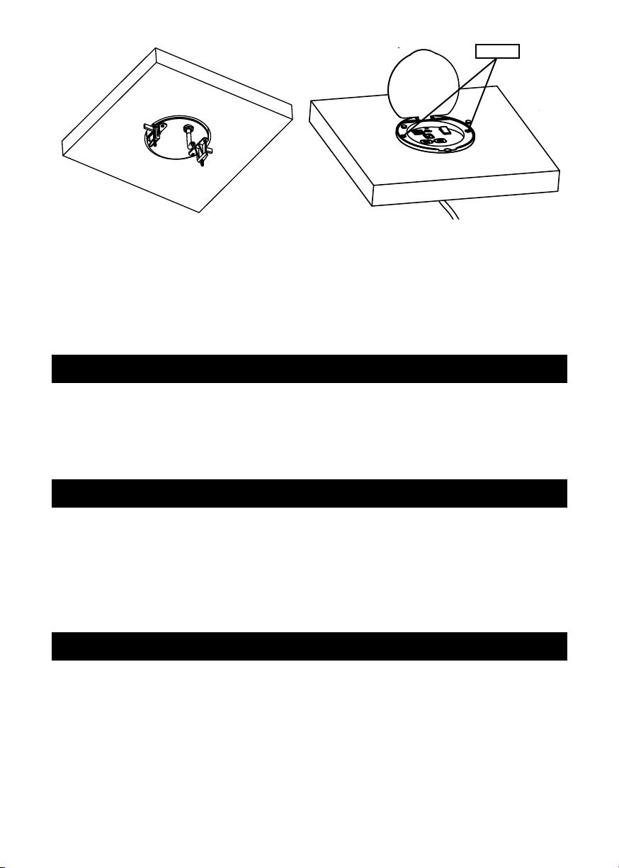
Insert product into the hole.
Tighten the screws ,the bottom of component will fix the board .
Install the protective screw cap cover.
Connect cable to power supply, once work has been completed correctly, the product is now ready to use.
4
12
1
2
3
4
5
Luen Yick Electrical Mfg. Co., Ltd.
Fig 2
• Put the screw covers over the screws
• Connect to mains power supply via the pre-wired cable and plug
• Switch on power supply and check for correct operation
This product must be disconnected from the circuit if subjected to any high voltage or
insulation resistance testing. Irreparable damage will occur if this instruction is not
followed.
The product should be recycled in the correct manner when it reaches the end of its life.
Check local authorities for where facilities exist.
Clean with a soft dry cloth only, do not use aggressive cleaning products or solvents which
may damage the fitting.
This product has a warranty of 1 year from date of purchase. Failure to install in
accordance with the current edition of the IEE Wiring Regulations, improper use, or
removal of the batch codes will invalidate the warranty. If this product should fail within
its warranty period it should be returned to the place of purchase for a free of charge
replacement. ML Accessories does not accept responsibility for any installation costs
associated with the replacement product. Your statutory rights are not affected.
ML Accessories reserve the right to alter product specification without prior notice.
WARNING
GENERAL
WARRANTY
Screws