Bastl Instruments KASTLE DRUM User manual

KASTLE
DRUM
BASTL
INSTRUMENTS

The Kastle Drum is aspecial edition of Bastl’sclassic mini
modular synth focusing on algorithmic industrial glitchy
drums.
How do you generate rhythm on apatchable drum machine
that has neither buttons, nor aprogrammable sequencer?
You discover it!
Drum sound synthesis with aunique dynamic acceleration
charged envelope makes this rhythm box surprisingly
versatile and extremely fun to play. The built-in VC clock
generator with astepped pattern sequencer can either run
on its own or it can be synchronized to analog clock, while
retaining the triangle LFO for parameter modulation.
The Kastle Drum is a mini modular synthesizer with
a headphone output, 2 in/out ports for interfacing other
gear, and it runs on just 3 AA batteries. It is ideal for
beginners in modular synthesis, but it will add some quite
unique functionality to any modular synthesizer system.
It delivers the fun of modular synthesis at alow price and
fits into your pocket so you can play it anywhere!
KASTLE
DRUM

Kastle Drum Features
8 drum synthesis styles
”noises” output for less tonal content
DRUM selects drum sounds
acceleration charge dynamic envelope
decay time
PITCH control with offset and CV input with attenuator
voltage-controllable clock with square and triangle output
stepped voltage generator with random, 8 step and 16
step loop mode
2 I/OCV ports that can be routed to any patch point
the main output can drive headphones
3x AA battery operation or USB power selectable by
aswitch
open source
durable black & gold PCB enclosure
What’sin the box
Kastle synthesizer
10 patch cables
sticker
for environmental reasons we are excluding the batteries
from the package
Kastle is a mini modular synth, and as in every modular
synth, the sounds are programmed by connecting outputs
to inputs. Outputs are labeled by agold outline around the
patch points. Inputs don’t have the gold outline. Feel free to
also connect inputs with inputs and outputs with outputs.
There’sno risk of damage, and sometimes interesting things
happen with unusual connections!
INSTRUCTIONS

1
0
14
4
5
8
14
2
3
3
9
9
9
6
7
4
11
10
12
1213
2
2
3
0 POWER UP
Find amicroUSB cable or go to your nearest store and buy
3 AA batteries.
Connect the USB cable to apowered 5V USB socket or
insert the batteries to the battery compartment the right
way - as indicated on the battery holder.
Flip the power switch to the USB or BATT position based
on which power source you are using. There is aLED close
to the TEMPO knob which should light up. If it doesn’t, it
means the USB socket is not powered or you connected the
batteries in awrong way or they are completely depleted.
1 OUT
Use the OUT jack to connect your headphones or an audio
cable from your speaker system. The main output of the
drum synth engine is routed to the DRUMS jack.
2 DRUM
At the core of the main sound chip there are 8 different
synthesis types falling into the categories granular noise,

fm, and experimental that are selected with the DRUM knob
(top right) and modulated with the DRUM MOD socket.The
DRUM MOD knob controls the amount of the modulation.
DRUM8
DRUM5
DRUM7
DRUM4
DRUM2
DRUM6
DRUM3
DRUM1
DRUM
B E AT 6 3 2 8 5 1 4 3 7 5 4 8 6 3 5 5 2 1 1 3 2 1 2 1
DRUM
MOD DRUM
MOD DRUM
MOD
DRUM DRUM DRUM
Making Drum Beat
PATTERN
3 PITCH
Turn the PITCH knob to adjust the PITCH of the main drum
synthesis. Amodulation signal can be connected to the
PITCH MOD socket and the PITCH MOD knob controls the
amount of the modulation.
D E CAY
Dynamic
Envelope
Charge
Acceleration
Yeehaw
4 DECAY
Dynamic Acceleration Charge Envelope
DECAY controls decay and pitch modulation depths with
avery unique dynamic acceleration envelope.

There are 2 ways to trigger or “charge” the main envelope
that will produce an audible sound.
The envelope is always discharging at the rate set by the
DECAY knob. The center position of the DECAY knob results
in short, snappy envelopes and turning it counter-clockwise
increases the depth of modulation applied to both pitch and
amplitude, as well as the decay of the modulating envelope.
However, turning DECAY clockwise from the center position
will increase the decay time, but only resulting in amplitude
modulation and no pitch modulation.
5 TRIGG IN
The TRIG IN will trigger the envelope with varying intensity
based on how much change in voltage there is at the input.
This will result in accented dynamic rhythms.
The TRIG IN is detecting 3 voltage zones between 0and
5 volts. Transitioning between zone 1 and zone 3 (or
back) will trigger the envelope with full intensity, however
transitioning through zones 1 and 2 or 2 and 3 will result
in the envelope being triggered with lower intensity and
therefore also shorter decay.
DRUMS
ENVELOPE
TRIG IN ZONE
3
0V
5V
2
1
NOISES
ENVELOPE

INPUT
ENVELOPE CHARGE
ACCELERATION
Modulating the DRUM MOD input and opening the
DRUM MOD potentiometer will also charge the envelope
depending on the acceleration in the input voltage. If abig
difference of voltage is registered in a short amount of
time, the envelope will charge by alot (stepped voltage or
pulse signal) and if smoother signals are detected (triangle
waveform), it will gradually charge the envelope by smaller
increments, resulting in an attack envelope shape.
6 “DRUMS”
This patch point can be used as another signal for your
patch. When any other output is connected to this output,
it will be passively mixed with the oscillator output and will
go to the OUT jack. This is most useful for adding more
power by connecting the NOISES output.
7 NOISES
The NOISES output is another sound output with less tonal
and shorter noise-glitch bursts that could be potentially
used as hi-hats.
Triggering of the NOISES output is slightly different to
the “DRUM” output. On the TRIG IN, the loud envelope is
produced when transitioning from zone 1 to 2 or from 2 to 3.

Quieter envelope is produced when transitioning from zone
1 to 3 or back.
Modulating the DRUM MOD socked does not trigger the
NOISES output but modulating the PITCH MOD does.
It means that by modulating these inputs, DRUMS and
NOISES can be triggered independently.
8 MINUS AND PLUS
These patch points can be useful to set the FEED pin.
“+” can be used to offset any modulation signal and “-”
connects directly to ground so it can be used to connect
grounds between several instruments.
9 TEMPO
Tempo sets the speed of the modulation. The modulation is
displayed by an LED close to the TEMPO knob. Amodulation
signal can be connected to the TEMPO MOD socket and
the TEMPO MOD knob sets the amount of the modulation.
This is especially useful when creating more complex
modulation curves.
10 LFO
The LFO socket outputs triangle waveform, but it can be
altered by modulating TEMPO or triggering the CLK IN to
get some complex modulation shapes.
11 CLK
The CLK output socket outputs apulse wave in sync with
the LFO triangle wave. When the LFO triangle wave is
rising, the PULSE output is high and when it is falling, the
output is low. This signal can be used for synchronising
external equipment or modulating any of the parameters
on the Kastle.
PATTERN
The PATTERN generator is inspired by the Rungler circuit by
RobHordijk. It canproduce8differentvoltages. Itgenerates
new voltage four times per period of the LFO. When FEED
is not connected, the PATTERN output generates a16-step
pattern. When it is low (or connected to “-” patch point), it

generates an 8-step pattern. When it is high (or connected
to “+” patchpoint), it keeps generating arandom pattern
and when it is altering, it generates asemi-random pattern.
The PATTERN output is useful for modulating every single
parameter of the Kastle synth or any external device with
the I/Oport.
For rungler nerds only:
The PATTERN voltage is based on the current state of
3bits of internal binary 8 bit shift register. The shift register
is shifted with every new voltage generated. When this
happens - based on the signal at the FEED socket - the
new bit arriving to the shift register remains the same
(FEED is low), is inverted (FEED is not connected) or is
generated randomly (FEED is high).
CLK IN
The CLK IN resets the phase of the TEMPO oscillator to the
highest point of the triangle and then the triangle begins
to fall. This is very useful for creating complex modulation
curves or for synchronising with external clock. When
TEMPO is set much slower than clock at the CLK IN, the
TEMPO oscillator becomes independent and the CLK IN
only triggers the PATTERN generator. This way the LFO
could still be used to modulate at slow rates.
INPUTOUTPUT
The I/OCV port enables you to connect up to 2 modulation/
audio/clock signals from Kastle to external gear, or to
connect any external signal to modulate the Kastle. The
signals are output with astereo jack and the patch points
L and R connect either to the left or right channel. To use
both channels with amodular synth, you can use stereo
to mono splitter adapter or you can just use one channel
(L) with a mono cable connected to the I/O jack. When
connecting external modulation to Kastle please note that
the signal will be rectified and Kastle will respond to 0-5V
signals only.
Other Bastl Instruments Synthesizer manuals
Bastl Instruments
Bastl Instruments KNIT RIDER EXPANDER v1.0 User manual
Bastl Instruments
Bastl Instruments SKIS V1.0 User manual
Bastl Instruments
Bastl Instruments SPA V1.0 User manual
Bastl Instruments
Bastl Instruments MULTIPLE User manual
Bastl Instruments
Bastl Instruments KASTLE v1.3 User manual
Bastl Instruments
Bastl Instruments Trinity XOR User manual
Bastl Instruments
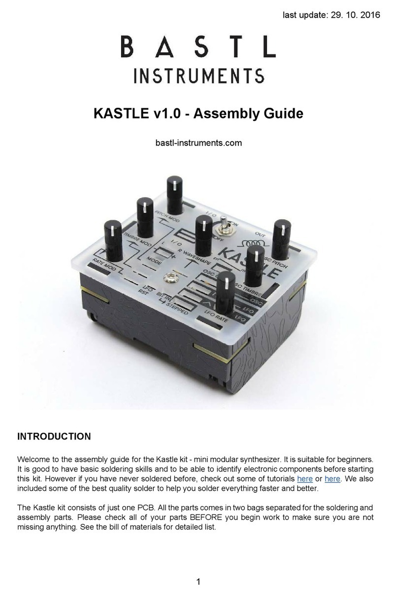
Bastl Instruments KASTLE v1.0 User manual

Bastl Instruments
Bastl Instruments KASTLE User manual

