Yamaha S90 ES Supplement

y
S90 ES
Power User:
Working with and Understanding
Physical Controllers
How to use this document:
This is a tutorial and assumes you are making the button pushes as it advances. By following the example setup,
you will gain an insight into how the controllers work and how they can be assigned to your advantage. All
possibilities could never be covered in a short guide but this should get you on your way. After going through this
article feel free to experiment with other assignments.
Background:
Get your S90 ES DATA LIST booklet and refer to the CONTROL LIST on page 42: “VOICE CONTROL SET
DESTINATIONS” and “ASSIGN A/B DESTINATIONS”. You will also want to refer to the EFFECT PARAMETER LIST
(pages 27-35).
Phil Clendeninn
Senior Product Specialist
Technology Products
©Yamaha Corporation of America

Assigning Controllers in Voice Mode
Within the architecture of each internal AWM2
(sampled-based) Voice is a set of 6 controller
assignment setups, called Control Sets. You can
program how the physical controllers will be
assigned to affect a specific part of the sound. The
assignable physical controllers available in the
Control Sets are:
MW – Modulation wheel
PB – Pitch bend wheel
AT - Aftertouch
FC1 – Foot Controller 1 (optional FC7 pedal)
FC2 – Foot Controller 2 (optional FC7 pedal)
FS – Foot Switch (optional FC4 or FC5 pedal)
Assign 1 – Slider
Assign 2 – Slider
BC – Breath Controller (optional BC3a)
RB – Ribbon Controller (*)
* The S90 ES does not have a Ribbon Controller.
However, keep in mind that if the same MIDI Control
Change messages as set here are received from an
external device, the internal tone generator also
responds to those messages as if the Ribbon Controller
of the instrument was used. Voices that were
programmed for the Motif ES, for example, might have
RB (cc22) assigned – the S90 ES Voice can still respond
to these in sequence data or via MIDI.
What about the Assign A and B Control Sliders?
ASSIGN A and ASSIGN B Control Sliders do not
appear in the individual Voice mode Control Sets.
Both are each assignable for the entire S90 ES
(global) and will behave the same in all Programs.
This is different from Assign 1 and Assign 2,
where the “destination parameter” is
programmable, per Voice.
What about the Sustain pedal and the new Half-
damper and the Damper Resonance functions?
This will be the subject of a separate article. But,
in general, the Half-Damper function is part of
the VOICE mode Amplitude Envelope Generator
on a per Element basis and is tied to the FC3
(optional) sustain pedal; while the Damper
Resonance, which simulates the soundboard
resonance inside a piano when the sustain pedal is
pressed, is a special Insertion Effect controllable
via the sustain pedal.
Control Set Conventions:
Certain Control Set assignments are common to
all elements and others can be specific to a
particular element of the sound. There are 6
Control Sets, each allows the user to pick a
physical controller and assign it a parameter
destination (the target parameter you will be
changing). It is possible with this system to assign
more than one controller to the same destination
by using more than one CONTROL SET. And it is
also possible to have a single destination under
the control of more than one physical controller.
The degree or depth of the control of each
physical controller can be programmed, as well. In
fact, the Depth parameter is very important –
because without a Depth amount the assignment
is meaningless. Think about the Depth setting as
controlling how far the controller will be moved to
get the response you wish. This is your
performing gesture and should be set to your
particular taste and playing style. It is okay to
have an opinion about ‘how much’ you move a
controller to get the response you need.
You can view and set the parameters for the
Controller Setups in the S90 ES itself or via the
“Voice Editor for S90 ES” in your computer.
To navigate to the Controller Sets in the S90 ES
from Voice mode:
•Press [EDIT]
•Press [COMMON] (a/k/a Drum Kits/Favorites)
•Press [F4] CTL Set
•There are 6 sets (3 pair) selectable via the
[SF1]-[SF3] buttons
•Setting the SOURCE/DEST: select a Source
controller and assign a target Destination
(Dest) parameter.
•Destination Elements or Common: The
‘ElementSw’ (or Element Switch) activates
control for each element. If the destination is
‘common’ to all elements you will see
parenthesis (----) around the four dashes that
represent the individual elements. Parenthesis
around a parameter means you cannot get at
it (This is the equivalent of being ‘grayed-
out’). In this case because all Elements will be
treated together. The Common parameter
destinations are Volume, Reverb Send or
Chorus Send. If, however, the destination can
be assigned to a specific Element(s) you will
see the destination parameter name as ELM-
Lvl = Element level, ELM-Dly = Element
delay, or ELM-Pan, etc. You can select which
elements are to respond to this control
setting. An “ElementSw” Element Switch
setting of “-2--“, represents a setting where
2

element 2 will be affected, and the others are
unaffected. (See example assignment below).
•Real-time Control over Insertion Effects:
Other possible destinations include real-time
control over the powerful DUAL INSERTION
EFFECTS that can be applied to a VOICE.
Refer to the Effect Parameter List (page 27-
35) for an idea of potential here. When
targeting a control destination if an effect
parameter can be real-time controlled you will
see an abbreviation of the parameter name
appear in the Control Set. If not controllable
in real-time, the parameter will be designated
with a “P” number, as in “INS2P10”. For
example, call up the B3 Organ sound
PRE1:118 [Or:16+8+5&1/3]; This Voice
uses the Dual Rotor Speaker 2 algorithm for
INSERTION B. You will find data about this
effect on the bottom right of page 30 of the
DATA LIST booklet. Navigate to its Control
Set1/2;
•Press [EDIT]
•Press [COMMON]
•Press [F4] CTL SET
•Press [SF1] Set1/2;
This Voice has the destination set to
“INSB:EfSpCtl” which translates to “Insertion
Effect B: Effect Speed Control”. It has two
speeds (like a Leslie) Slow and Fast. This
Control Set is using the Mod wheel to switch
between Slow/Fast speeds. Most of the
parameters of the Dual Rotor Speaker 2
algorithm are assignable for real-time control.
There are 16 possible parameters in the
processor. “Speed Control” is listed as MIDI
Parameter Number 16. MIDI Parameters 10
and 15 are unavailable for real-time control
assignment. If you attempt to select them you
will see “INSB:INS2P10” and “INSB:INS2P15”
instead of a parameter abbreviation –
meaning they are unavailable. (MIDI
Parameter Number 10: (typically Wet/Dry
Balance) is totally unavailable because of
phase cancellation possibilities - it is not even
listed; and Number 15 “Microphone L-R angle”
is the angle of the modeled stereo microphone
on the Leslie cabinet…simply not a parameter
you would move in real-time. Mic angle is a
“set and forget” parameter. Parameters that
are unavailable typically have no musical or
practical use. If you want to see and tweak
this effect algorithm press [F6]: EFFECT/
[SF3]:INSB
•DEPTH The setting here must be set with
care and some thought. The range here is
from –64 ~ 0 ~ +63. How the S90 ES
responds to a setting will depend on which
parameter and which controller is selected.
(See below some example assignments). A
Depth setting of 0 defeats all other settings in
the Controller Set and renders them
meaningless. In general, the higher the
number the more it increases the range of
control. Negative value settings reverse the
effective direction of the controller. You will
have to be logical here when making
assignments. …More on this in a minute.
How the assignment of controls works
Example Assignment: In this example we deal
with controlling VOLUME via controllers within a
S90 ES sample-based Voice. This can be tricky,
but this example should make clear how it works.
--Let’s say you want to control the total Volume
of the Voice with the Modulation Wheel. MIDI
control change message #001 is the Modulation
Wheel. The modulation wheel can be assigned to
control all manner of parameters within a
synthesizer, not just vibrato (Pitch Modulation
Depth). But for our example let’s see what
happens when you attempt to assign the MW to
control overall volume. For our experiment let’s
initialize a voice. This way we are not inheriting
values from a preprogrammed Controller Set.
From Voice mode:
•Press the following buttons:
•Press [JOB]
•Press [F1] INIT
•Press [ENTER]
•Press [INC/YES] to execute.
This will create an INIT VOICE with just a piano
wave in it.
•Press [EDIT]
Let’s select a synth wave. Navigate to the
OSCILLATOR WAVE page:
•Press Program button [1] to drop to the
Element level of editing. (Notice the
Inverse video ‘E’ and the ‘EL1’ on the top
line – denoting the Voice has been edited
but not yet stored and we are editing
Element 1.)
•Press [F1] OSC
•Press [SF1] WAVE
•Select sample wave #0612 [Wv:UniBass]
3

•Now, for fun, let’s activate a second
Element in this Voice. Press the Program
[2] button that represents Element 2. You
can now turn the Element Switch ON.
•Set Element 2 to waveform #0630
[Wv:FMSquare ]
•You can use Program buttons [1], [2],
[3], and [4] to select Elements, and
buttons [9], [10], [11], and [12] to turn
them on/off. Try it! Currently we can use
[1] and [2] to select and [9] and [10] to
mute and un-mute our two Element Voice.
This will allow you to isolate each element
when you want to concentrate on just one
at a time. Practice this basic skill.
•Navigate to the CTL Set 1/2 (Control Set
1) page. (Press the [COMMON] button to
return to Common edit. [F4]:CTL SET
•Set the CTL SET 1 as follows:
In the above example, the Volume parameter is
‘common’ to all Elements. We know this because
the Element Switches are grayed out
(parenthesis). If you were to activate additional
Elements they would also share the same setting
when you select a ‘common’ destination. The
modulation wheel will effect all the Elements. The
+63 Depth setting sets the maximum range of
the controller. Try it...move the mod wheel…
Hey! What gives...I thought we would now be
controlling the volume completely with the
modulation wheel! But no, it doesn’t work. Is the
unit broken? Should I call someone? - Not at all.
Here’s why it is not working: This is not the place
that the overall volume of the sound is set, only
where you assign control to it. We need to go to
the overall Voice volume parameter and reduce it
to zero. In other words something else is
controlling how loud this sound is as well – of
course, it’s the main Volume assignment that
responds to note-on. Here is how to change it.
Navigate to the Common OUTPUT page [F2]. Here
you will see a parameter for the total volume of
the Voice = 127. Program it to 0. That’s right, 0.
Now when you move the modulation wheel you
have total control over the volume of the Voice.
The position of the modulation wheel is now an
absolute representation of the current common
volume, 0-127. We call this process ‘biasing’ the
parameter (in this case, volume) to the controller.
In other words, it will now look to this controller
(mod wheel) for volume instructions.
Okay, return the Common Voice Volume to 127
before continuing.
Similarly, a volume assignment can be made on
the Element level. This would allow the
player/programmer to have control over specific
parts of the sound (Elements) within a Voice. In
our Control Set instead of making the Destination
= Volume (common overall volume) like before,
this time assign it to ELM-Lvl or Element Level.
When ELM-Lvl is selected you can individually
assign which elements will respond to this Control
Set’s Depth setting when the physical controller is
moved.
Return to Control Sets press [F4]:CtlSet/
[SF1]:Set 1/2. Select ‘ELM-Lvl’ as the DEST
(destination). Set only Element 2’s level to be
controlled via the MW (Element Switch). This is
accomplished by moving the cursor to the
Element Switch line and setting it so it reads:
“-2—“
4

And in a similar fashion to before, you would need
to set the initial level of the Element(s) that you
are controlling to zero (bias its level to the MW).
Instead of “Total Voice Volume” we are looking for
the level of this particular Element. This is found
on the Element Amplitude page: Return to
Element Level editing by pressing program button
[2] (Element 2 Select)
Then press [F4]:Amp/ [SF1]:Lvl/Pan
Set EL2 Level to 0
When you set Element 2’s Level to 0, it is biased
to the MW. This is a very flexible arrangement.
You can expand upon it and dream up your own
configurations. For example, you could take
Control Set 2 and program it to control just
Element 1 with the same Mod Wheel but set the
ELM–Lvl DEPTH to –64. Now when you move the
wheel it will fade out one sound and fade in the
other.
Notice you did not have to set the Element Level
for Element 1 to 0. This is because if you did and
then applied a minus value to it…this would be
illogical…because levels below 0 are still inaudible.
Experiment.
A similar scenario occurs when you assign a Voice
to Breath Control. You want the Voice to only pay
attention to (be biased to) input from the Breath
Controller (cc #002). In such a case you may
want to reduce the overall volume of the Voice to
0 or the element level to 0. Which one you use
will depend on what it is you are trying to
accomplish. This way the volume will be entirely
determined by the amount of breath pressure
applied to the BC3. Note-ons do not turn the
sound on alone. They must be accompanied by a
burst of breath (air) pressure (cc #002) applied to
the mouthpiece.
Note: It must be stated here that Breath Control works
best of all on VL physical modeled voices (optional
PLG150-VL board). The Virtual Acoustic technology is
meant to respond perfectly with breath control input. In
the technology there is an acoustically accurate change
in timbre, pitch and amplitude in response to BC
‘pressure’ control. The sound of VL will mimic the
‘behavior’ of acoustic instruments. When controlling
non-VL type voices you might try assigning breath
control (BC) to vary the cutoff frequency of the filter. In
such a case you may want to program the initial value of
the filter to something other than zero – set to taste.
This would require you to go into the Voice element level
and set the cutoff frequency of the filter for each
element you want to control. Each element can have a
different filter type and cutoff/resonance. Each element
that you add can have its own filter and filter settings.
Note 2: When using Breath Control on sampled-based
Voices you may find it easier to just reassign the BC to
Expression. Here’s how: from Voice mode press
[UTILITY]/ [F3]:VOICE/ [SF3]:CtlAsn and set BC = 11
Expression. This will allow you to immediately control
any internal sound with BC - without any further
programming.
FOOT PEDALS
The same scenario holds true for controlling
volume with an optional Yamaha FC7 (sweep
control pedal) plugged into the Foot Control jack
(FC2). Foot Control (cc #004) can be assigned to
control many different parameters within a synth
voice. (Not to be confused with Foot Volume (cc
#007) which always controls MIDI Channel
Volume). There is always some confusion here
because they both use the same FC7 pedal –
however, the function can be quite different. One
key difference is that if you use cc007 every thing
connected to that MIDI channel will be controlled
the same. If you use the assignable Foot Control
cc004 you can choose the destination parameter
for the foot pedal and it will only affect the S90 ES
and only the Elements of the S90 ES sound that
you designate.
Foot Control (cc004) can be assigned to control
the internal volume of the S90 ES in a similar
fashion to how we did the MW experiment. Simply
follow the same steps we did with the MW, above,
to assign the Foot Controller (FC04) to be the
Source and set volume as the (DEST) destination.
When you set the Volume to 0 you will have
biased total volume to the Foot Controller.
Note: If the parameter to be controlled is set at any
value other than 0, you are, in affect, setting a
minimum value. In the case of our volume example, this
would be the minimum volume when the controller was
in the heel down position. In some instances you may
wish to set the minimum to a value other than zero as
the stored condition (especially for Live players this is
invaluable). The example above is useful in a scenario
where you want to control the internal S90 ES sound
with a separate foot pedal from what is sent via MIDI.
After any and all Voice edit procedures you should
STORE and then SAVE data (if it is worthy of
5

keeping). If you started editing a Preset or you
started editing an Internal Voice, simply point the
Store procedure towards a desirable Internal
location. Press [STORE]; Select a location; press
[ENTER]; then [YES].
Note: At the end of any editing session you should
make a backup copy of all your new Voice edits. Save
sounds either to an optional USB Drive, in an ALL or
ALL-VOICE files or backup the current set via a S90 ES
Voice Editor
What other things can be assigned?
To answer this question we must recognize that
there are answers for internal
Voices/Performances and answers for external
communication via MIDI Master Keyboard setups.
Let’s first gain an understanding of how the
controllers work. MIDI provides for standard
physical controllers. Some are fixed as to what
control change message they send, while others
are assignable. We must consider what these
controllers are doing to the internal S90 ES
sounds and what they are doing out via MIDI.
These two things can be quite different, by
design.
First, here is how it works with Voices. S90 ES
Voice banks hold the factory programmer’s best
work. These are your fundamental, playable
sound Library. A Voice can have as many as four
completely independent multi-sampled waveform
sets within it – Yamaha calls these components
Elements. Each Element can be individually
controlled by S90 ES parameters such as filters,
envelopes, LFOs, etc. You can assign the various
physical controllers to control specific areas within
the sound. The physical controls available are:
PB – Pitch bend wheel
MW – Modulation wheel
Assign 1 – Slider 3
Assign 2 – Slider 4
AT – Aftertouch
FC1 – Foot Volume (Expression)
FC2 – Foot Control
FS – Foot Switch
BC – Breath Controller
SUS – Sustain
Assign A – Slider 1
Assign B – Slider 2
Control Sliders 1 / 2 / 3 / 4
RB – Ribbon Controller
PB (fixed) – Pitch Bend wheel will always send
information that is Pitch Bend data (its own
category of message) both internally and out via
MIDI. Exactly how the data is interpreted by the
tone generator (receiving device); is
programmable. For example, it is possible to use
the wheel for something other than just pitch
bend by programming the sound to have a pitch
bend depth of 0 and then assigning the PB wheel
to a different parameter. For example, in physical
modeling VL technology (PLG150-VL) the PB
wheel is often used for embouchure (mouth
position/tightness of the lips) – most horns don’t
pitch bend like a synth. It makes a good control
for embouchure because embouchure can be
tightened (wheel up) or loosened (wheel down) or
returned to normal (centered). These VL Voices
are often programmed such that the PB range =
+0. Typically, however, on the internal AWM2
sample-based Voices PB range is set to up/down 2
steps (a whole step; see below).
Pitch Bend range is a COMMON parameter and
can be set per Voice on the following screen:
•Press [COMMON]
•Press [F1]: GENERAL
•Press [F5]: OTHER
The Pitch Bend wheel actually sends out 16,384
different units, how far this bends the pitch is
always determined in the receiving device. While
raising the pitch bend wheel in the screen shot
above will raise the pitch two half steps, out via
MIDI a receiving module might see this as an
octave or a fifth (how far the PB changes is always
determined in the receiving device).
MW (fixed) – Modulation wheel will always send
control change message 001 and this data is
typically used for vibrato depth both internally and
out via MIDI. Exactly how the data (control
change message 001 – written cc001) is
interpreted by the tone generator (receiving
device); is programmable. For example, it is
possible to use the modulation wheel for
something other than just vibrato depth by
programming the sound’s PMD (pitch modulation
depth to 0) and assigning it another parameter.
(PMD is another name for vibrato.)
For example, the mod wheel makes a good mix
control. You can use it to fade one layer in (+
depth/level at 0) while a second layer is
programmed to fade out (- depth/level at 127).
The assignment to vibrato (Pitch Modulation
Depth) is not automatic. Each Voice that uses the
MW as vibrato has it assigned in a Control Set:
6

Above you see a typical synth lead Voice
PRE4:064 [Ld:Bright Saw]. A two Element Voice
that has the Mod Wheel as the ELFO-PM depth
control – this translates to Element Low
Frequency Oscillator- Pitch Modulation control.
Depth = +27. As you move the wheel up you will
add vibrato (pitch modulation) to the Voice
AS 1 – ASSIGN 1 does not have a fixed MIDI
message (while all decent MIDI keyboards have
Modulation Wheels and Pitch Bend wheels, they
do not necessarily have an assignable controller).
It can be assigned as an internal control device.
You can use Assign 1 to change Element level,
filter cutoff/resonance, effect send, etc., etc. (see
Control Set Destination list). It can be assigned to
any of 68 locations. It can independently be
assigned any control change message, (cc1-
cc95), for transmitting out via MIDI. The default
assignment is cc #016 called: “General Purpose
control 1”. If you reassign the default control
change assignment (a global setting found in
UTILITY) to cc #001 Modulation, for example, you
will in effect have a modulation wheel on a Slider.
However, leave it set at cc016 as this is as good
as any for its purpose.
AS 2 – ASSIGN 2 does not have a fixed message.
It can be assigned as an internal control device.
You can use it to change Element level, filter,
effects, etc., etc. (see Control Set Destination
list). It can independently be assigned any
control change message for transmitting out via
MIDI. The default assignment is cc #017:
“General Purpose control 2”. If you reassign the
default assignment (global setting found in
UTILITY) to cc #002, for example, you will in
effect have a breath control on a Slider.
AFTERTOUCH (fixed) – will always be sent when
extra pressure is applied to the key. How this
controller data is interpreted, if at all, is a function
of the voice parameters in the tone
generator/receiving device. Some players use
aftertouch to vary PMD (pitch modulation depth),
vibrato. Others like it to brighten the sound and
assign it to filter cutoff, still others assign it to
control an effect, like the rotating speaker speed.
Try substituting AT for MW in the
OR:16+8+5&1/3 Voice… as long as you apply
pressure to the keys, the speed of the rotary
speaker will be fast. Aftertouch cannot be turned
off, per se. It is always sent when pressure is
applied to the keyboard. Whether or not anything
happens when this pressure is applied is
determined completely in the receiving device.
FOOT CONTROL 1 (FC1) – An FC7 pedal
plugged into the Foot Control 1 jack is available as
an assignable controller. You select what it will
send globally for the S90 ES from VOICE mode
UTILITY:
•Press [UTILITY]
•Press [F3] VOICE
•Press [SF3] CTL ASN.
The default is cc011 (expression) which is similar
but not the same as control 007 (Main volume).
Many people mistake these two as being the same
thing. While they both control ‘how loud’, they
have different functions. For example, in a Song
you plan to play a B3 Voice on top of a sequenced
rhythm section. You set the organ Part’s mix
volume to a level of 96. (Because 96 is the perfect
setting for as “loud” as you will ever need to be
compared to the rhythm section). You are setting
how loud the organ sound will play on a scale
from 0-127 - relative to the other sounds. If your
FC1 pedal is set to control 011 (expression) – toe
down will never exceed the ‘96’ Main volume
setting of the Part. If, on the other hand, you
have the FC1 assigned to cc007 (Main volume)
the volume will be set by the absolute position of
the pedal – toe down will reset the volume to 127
– and you will be too loud. Expression (cc11) is
relative volume within the maximum set by the
individual parts Level. Volume (cc07) is absolute
volume for the current MIDI channel.
FOOT CONTROL 2– defaults to sending control
change message 004, but can be reassigned to
any control change number 1-95 (global setting
found in UTILITY). How this data is interpreted by
the tone generator/receiving device; is
programmable. For example, it is possible to use
the foot control for filter cutoff (wah-wah) on an
internal sound and have an external sound set to
interpret cc #004 as something entirely different.
FOOT SWITCH – Use an optional Yamaha FC4 or
FC5 (momentary switch). It can be assigned any
cc number between 1-101. It will always send a
control change value of 127 when activated;
7

otherwise the value is 0. The nature of the switch
makes it ideal for OFF/ON operations. This
message can be used to turn something from off
to on or vice versa. The default assignment is cc
#088 an unassigned number. Assigned to cc #099
or 100 you can advance or move backward
through Voices or Performances. You could even
use it to start/stop the arpeggiator (cc96*), hold
the arpeggiator (97*) or the sequencer (cc98).
*The S90 ES default for Arp Sw and Arp Hold. Use cc090
when you want to Stop an arpeggio during sequence
playback. This cc message can be placed on a track to
automate the arpeggio ON/OFF.
Set FS to cc66 it will become a sustenuto pedal.
Set to 101 it will reset the OCTAVE transpose.
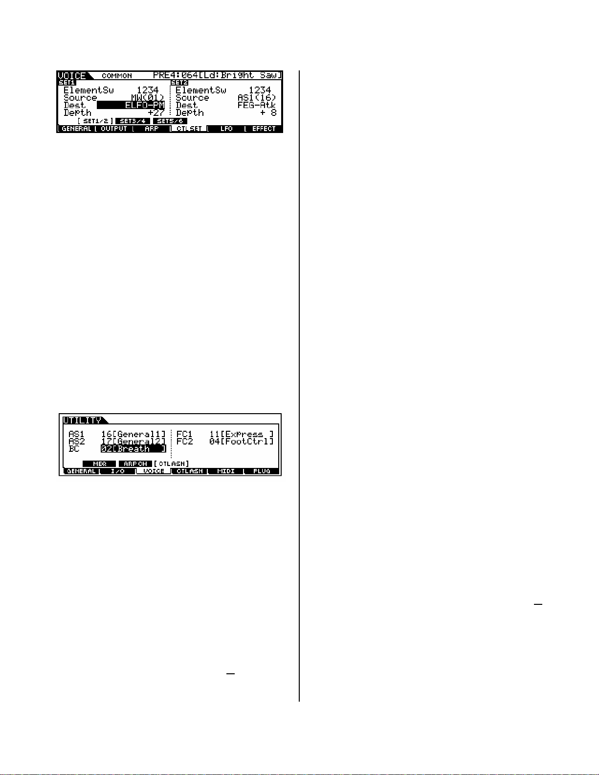
BREATH CONTROL – defaults to sending control
change message 002, but can be assigned to any
cc number from 1-95 (global setting found in
UTILITY). How this data is interpreted by the tone
generator; is programmable. For example, in VL
Voices (PLG150-VL) breath control often applies a
virtual ‘Pressure’ to the virtual mouthpiece (or
driver), and can be responsible for parameters
like Scream and Throat Formant. Setting BC to 11
Expression is a quick way to assign sample-based
Voices to BC. This is accomplished for Voice mode
by press [UTILITY]/[F3]:VOICE/ [SF3]:CTL ASN
SUSTAIN (fixed) – will always send a control
change message 064. This control number is
HOLD 1 and will latch the current sound. (Other
controllers can be assigned to send cc064 sustain
but a pedal plugged into the sustain jack will
always send sustain). When activated how long
the sound sustains will be a function determined
by the Voice’s own programming. The Amplitude
Envelope Generator determines what happens to
a sound over time. The sustain parameter will not
hold a sound indefinitely if the AEG has a DECAY 2
LEVEL that ultimately reaches 0. Typically an
organ envelope is an example of a sound that will
sustain indefinitely – because an organ envelope’s
DECAY 2 LEVEL remains at maximum (127). If the
DECAY 2 LEVEL of the AEG is 0 the sound will
eventually die out completely. If the DECAY 2
LEVEL is set to any value other than 0, then the
sustain parameter will HOLD it at that level.
SUSTAIN (half-damper) – the S90 ES
represents the first of the Yamaha professional
synthesizers to implement the very “pianistic”
half-damper function. This requires that a special
parameter be activated in the Voice’s Element
AEG and that an optional FC3 pedal be used. In
general, the FC3 is continuous sustain pedal that
is capable of sending message form 0 through
127, unlike the regular sustain pedal which is a
simple ON or OFF proposition. But the magic of
the half-damper function is in the S90 ES itself.
What it means is you can get the subtle nuance of
how a piano responds when the pedal is not fully
pressed. This allows for greater expressive playing
on piano pieces. Until know this feature was only
found on the dedicated Yamaha electronic pianos
(and, of course, on all the Yamaha acoustics ☺.)
Plugging an FC3 into a keyboard that does not
have the AEG to take advantage of the half-
damper will get you nothing – the magic is as
much in the S90 ES as it is in the pedal.
Sustain pedal and the Damper Resonance
Effect – new to the S90 ES as well, is the Damper
Resonance Effect. This is an additional Insertion
Effect developed with the acoustic piano in mind
and allows the sustain pedal to control the
amount of soundboard simulation you hear when
the sustain pedal is pressed. The Damper
Resonance is a subtlety that adds to the
significant realism and playability of the S90 ES
piano sound.
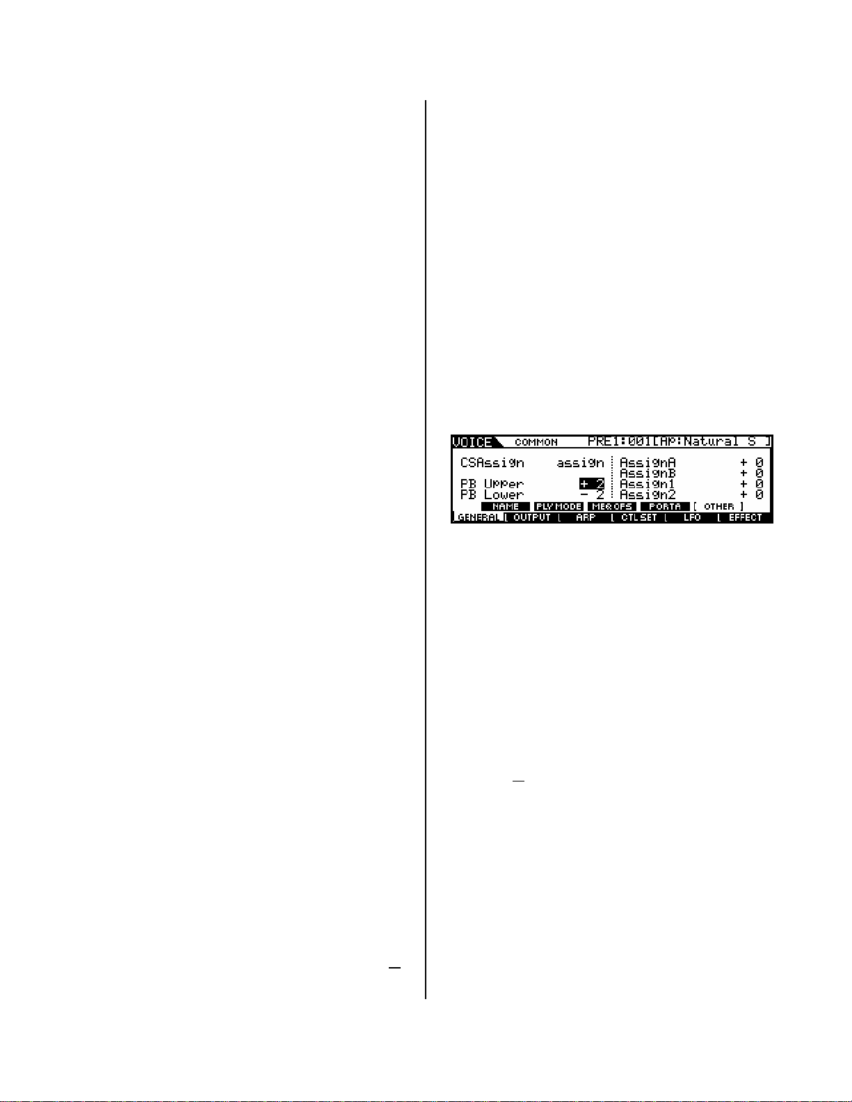
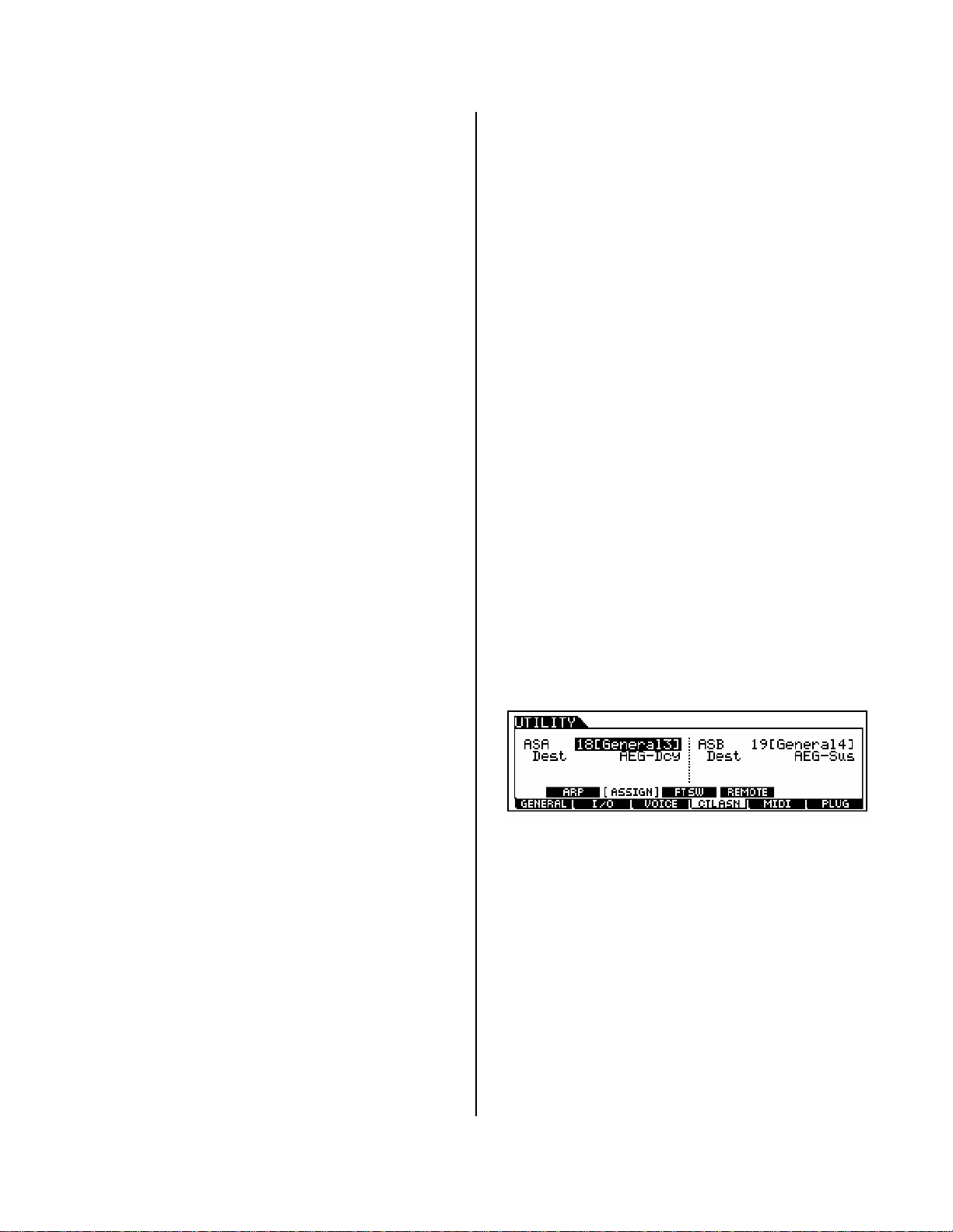
Assign A / B – default to cc18 and cc19 but are
assignable to any control change number.
Additionally, and independently they can be
assigned to System Controller Destination
parameters (Master EQ, Arpeggio, and other
global parameters). See page 42 of the DATA LIST
booklet for more details. These are assigned
globally in UTILITY mode. The default
assignments have these 2 Sliders controlling
Amplitude Envelope Sustain and Decay
parameters internally.
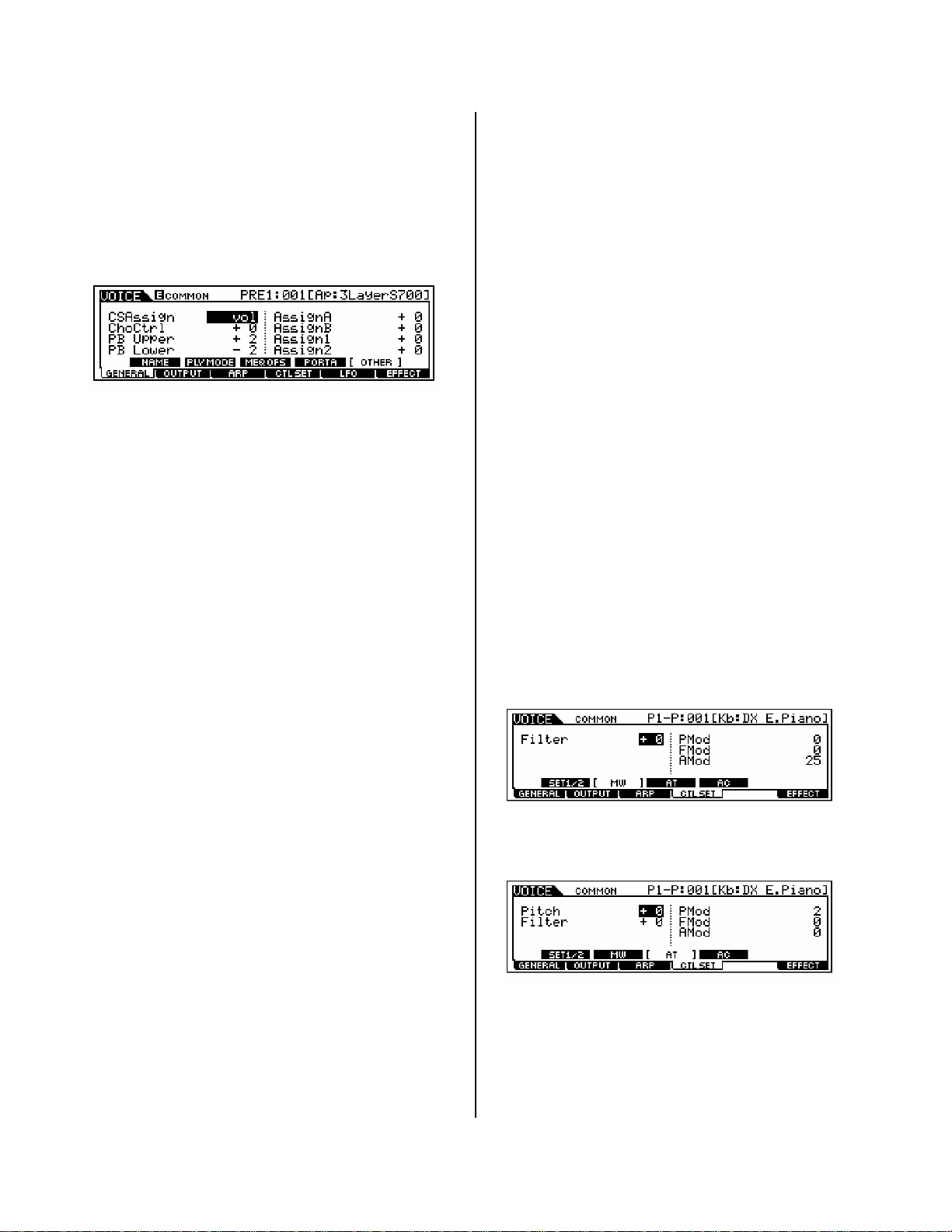
CONTROL SLIDERS 1 / 2 / 3 / 4 – These can
be used for a variety of functions as defined by
the [CONTROL FUNCTION] section. Options are:
•Pan/FX Send/Tempo;
•Filter/EG;
•Assign
•Master EQ
•Volume
•Zone
When the LED is set to the Volume row, they
default to controlling levels via Sysex messages in
both Voice and Performance modes. They are
assignable per zone in a 4-zone Master Keyboard
setup to Control Change message. (See separate
section below). In a Master Keyboard setup they
are individually programmable – CS 1 will be for
zone 1, CS 2 for zone 2 and so on. But you select
the parameter they each control. The row that is
8

active when you initially call up a Voice is a
function of the [CONTROL FUNCTION] section and
is programmable per Voice. When set to VOL, as
below, the Sliders will send System Exclusive
messages to control the Element levels within the
Voice. (When selected in a Performance the
Sliders control Voice levels with the Performance).
When in a MASTER Setup you will most likely
select ZONE as the active row making the Sliders
then programmable per Master setup.
Control Sets Summary: Each AWM2 (sample-
based) S90 ES Voice has six Control Setups where
a physical controller, called the Source, is
assigned a specific controllable parameter, called
the Destination (DEST) and a Depth value that
determines how much effect the controller will
have. This flexible system will enable the user to
tailor the sensitivity of each controller’s
movement. Sensitivity or Depth refers to how far
you move the controller to get a desired result.
This is an important setting because you want to
be comfortable working the controller while you
perform.
The destinations are listed in detail on page 36 of
the Data List booklet that comes with your S90
ES. They include Voice volume, reverb send,
chorus send, and some 26 Insertion Effect
parameters (not all Insertion Effect parameters
are real time controllable). And if you are dealing
with the internal sample-based Voices, an array of
Common and individual Element parameters like
filter cutoff, resonance, LFO speed and depth,
tuning, key on delay, Pan position, Pitch, Filter
and Amplitude envelopes, etc., etc., can be
programmed. PLG1, PLG2 and PLG3 Voices will be
able to be assigned to volume, reverb send,
chorus send and the 26 possible Insertion Effect
parameters, only.
Each PLG-series board may have controller sets of
their own, depending on the technology involved –
these will be programmed in the PLG Voice Editor
software. For example, if you program (using the
provided AN Expert Editor) a PLG150-AN Voice to
respond to cc16 for filter cutoff and cc17 for filter
resonance, it will have its ‘virtual analog’ filter
controlled by the S90 ES Assign 1 / 2.
Note: PLG150-series Plug-in Voices will have a
different set of Controller Set screens in the S90
ES (explained below). Also, look in the Voice
Editors for additional assignable controller
routings. For example, the PLG150-AN has some 8
AC (assignable control devices) and 15 Control
Sets available. The PLG150-AN is based on the
AN1x keyboard synth, which had 8 front panel
assignable knobs AC1-AC8. You can reassign as
many as you wish to your available S90 ES
physical controllers. Each board will have a
different controller setup arrangement depending
on the technology involved.
PLG150 Series boards are single PART boards and
have two kinds of Voices: PLUG-IN and BOARD.
PLUG-IN Voices are those that have been
integrated with S90 ES Effects and Controller
routings (discussed below). BOARD Voices are
resident on the Board itself and have not yet been
integrated with the host parameters (hopefully
you will customize them to your liking). Each
board comes with a different amount of Board
Voices for you to build PLUG-IN Voice and the S90
ES gives you 64 blank USER locations for you to
place them.
The PLG150 Voices will have the following
additional Controller (CTL) screens that will let
you route controllers to the following areas:
Modulation Wheel Assignment: In each S90 ES
PLG150 Voice you can assign MW to directly
control the Filter (cutoff/resonance); Pitch
Modulation (PMod) – vibrato; Filter Modulation
(FMod) – wah-wah; and Amplitude Modulation
(AMod) - tremolo.
Aftertouch Assignment: Aftertouch can be
assigned to Filter, Pitch Mod, Filter Mod,
Amplitude Mod and the direct control of Pitch with
(AT) key pressure
Assignable Controller: For each PLG150 Voice
you will find a screen for an Assignable Control –
AC Control. Here you can pick a device (physical
controller) or control change number to do various
tasks: Control the Filter, Pitch Modulation, Filter
Modulation, and Amplitude Modulation. These will
enable the user to customize routing for the
PLG150 Voices.
9

Depending on the PLG board you may have
access, via the S90 ES front panel, to selecting a
specific parameter to control with the AC selected
here. Look in the PLG boards NATIVE parameter
area.
Understanding how the Controller and the
Parameter ranges work:
Put on your thinking caps...this is tricky.
Remember I mentioned logic – well here we go.
Minimum-to-Maximum controls versus Negative-
to-Positive controls: Consider the Mod wheel
versus the Pitch Bend wheel as an S90 ES
physical control device. One has its zero position
in the middle, while the other is at zero in the
down position. One changes values from minimum
towards maximum, the other above and below a 0
center value. These factors must be considered
when you make an assignment of a parameter to
a physical control. Think about all physical
controllers in these two groups:
Minimum to Maximum Controllers
Modulation Wheel
Foot Controllers: FC1/FC2
Breath Controller
Aftertouch
Foot Switch/Sus *min. or max. only
Negative ~ 0 ~ Positive Controllers
Pitch Bend Wheel (self centering)
Assign 1/2 (center détente)
Assign A/B (center détente)
Control Slider 1/2/3/4 (center détente)
Now think about the parameters and the range of
possible values. Some parameters go from
minimum to maximum (like volume and effect
sends: 0-127) while others move above and below
a center zero point (pan position: L-C-R), and
filter cutoff: -64 more closed, 0 normal, +63 more
open).
This can be an issue if, for example, you assign a
minimum to maximum parameter, like Common
volume 0-127, to a negative to positive
controller like Assign 1.
Here’s what happens:
The center position will be 0 volume, while +63,
at the top, will be maximum volume. For all
settings below the center position, 0 through –64,
the minimum volume is sent out, 0. The control
seemingly only works half the time. You can’t hear
less than 0.
Conversely, if you assign a parameter that is
negative to positive to a controller that does not
have a center détente (a minimum to maximum
controller like MW), you may find it difficult to
place it back to neutral.
It is not an issue when you assign a
negative/positive parameter, like pan position, to
a negative/positive controller like a S90 ES Slider.
In such a case, negative values pan left, positive
values pan right and the center position is center.
Conclusion: Consider the above when selecting a
controller for a specific parameter.
The Control Sliders
There are 4 Control Sliders, CS1-CS4. We need to
talk about their function in Voice, Performance
and Master Keyboard modes.
Why don’t the Control Sliders send cc007 in
Voice Mode? The sliders send Element Level via
system exclusive messages. In Voices that
combine up to four (sampled) elements you have
a slider for each Element. Of course, they do not
send cc007 (Main Volume) in Voice mode – cc007
is main channel Volume and would affect all
components together (common) because they are
all on the same MIDI channel. You would lose
individual control. It would set all Elements to the
same Volume no matter which slider you moved.
Why don’t the Control Sliders send cc007 in
Performance Mode? The sliders send Voice
Level again via system exclusive messages –
which will affect only the S90 ES. In a
Performance that has up to 4 Voices each slider
controls the volume of one of the Voices.
Performances can combine Voices and PLG150*
Voices. *One Voice contributed per PLG150 series
board. Of course, the sliders do not send cc007 in
Performance mode. Again you would lose
individual control because a channel message
would set all Voices to the same Volume no
matter which slider you moved. All Voices in a
Performance are on the same MIDI channel.
What about the Control Sliders in Master
Keyboard Mode? The sliders are assignable to
any control change number from 1-95, when you
are setting up a 4-zone setup. You determine
what each slider sends to each corresponding
zone. You determine the MIDI channel and
destination (internal TG or MIDI or both) for each
zone. The default is cc #007 (volume) for each
zone and this is sent out via MIDI (if you want).
10

Controllers can be activated or deactivated per
Zone. Of course, they can send cc007 in Master
mode because each Voice can be on a separate
MIDI channel!
What happens when I want to control Voices
in a Performance, independently?
A Performance is literally, up to 4 Voices
addressed together on the same Basic MIDI
Channel. If you want to control one Voice a
certain way and another a different way within the
same Performance you may need to program each
individually back in Voice mode. That is what you
learned about in this article – assignment of
controllers in Voice mode. You now can assign
parameters in a Voice and when you place that
Voice in a Performance all of your controller
routings will apply. This can be very interesting
because a single slider can be doing different
things to different Voices in your Performance…
…which is actually very, very cool. For example,
say you want to control a Performance with three
sounds: STRING/PIANO/FLUTE. And you want to
control the string sound independently with a
FOOT CONTROL pedal. You may need to program
the individual Voice, however, you do have the
option of activating or deactivating a controller for
an individual PART within a Performance. So you
will have to determine if you need to make
adjustments to individual Voices or can you simply
activate or deactivate certain controllers to
accomplish your goal. In a Performance you can
see which Controllers are active per Part:
•Press [EDIT]
Touch program button [1] to select PART edit
level/
•Press [F5] RCV SW or Receive Switch.
Here you can set each Part as necessary. An ‘x’
means the Controller is active on this PART.
In general, each Performance is pretty much
autonomous when it comes to control
assignments. In other words BC, Assign1,
Assign2, FC1, and FC2 can be assigned differently
per Performance, as necessary, whereas in Voice
mode the assignment for these was global.
One last tip concerning your controller
assignments: There is a default condition for each
when a Voice or Performance is recalled. This is
affected by the CONTROLLER RESET parameter
which can be set globally:
•Press [UTILITY]
•Press [F1] GENERAL
•Press [SF4] OTHER
This parameter can be set to either RESET or
HOLD. “Hold” will allow each Voice to inherit the
current condition of a controller. For example, if
you have a BC plugged in and the Controller Reset
is set to HOLD, you will not have to blow air into
the BC3 to initialize it each time. Therefore if you
are using a BC3 you want the value to HOLD.
If you use a Foot Controller as your master
Volume level, setting Controller Reset to HOLD
will mean that the next setup you call up will hold
at the current volume of your pedal. This makes
your pedal’s position “live” rather than having it
RESET to a pre-set value. You can choose which
way works best for you.
Cool…enjoy!
Phil Clendeninn
Senior Product Specialist
Technology Products
©Yamaha Corporation of America
11
Other manuals for S90 ES
3
Table of contents
Other Yamaha Synthesizer manuals

Yamaha
Yamaha P-150 User manual

Yamaha
Yamaha CS-5 User manual

Yamaha
Yamaha PortaTone PSR-450 User manual

Yamaha
Yamaha CS-70M User manual

Yamaha
Yamaha CS-30 User manual

Yamaha
Yamaha DX21 User manual

Yamaha
Yamaha DX7 II FD Owner's manual

Yamaha
Yamaha PortaTone PSR-260 User manual

Yamaha
Yamaha ARIUS YDP-181 Instruction Manual

Yamaha
Yamaha PF2000 User manual