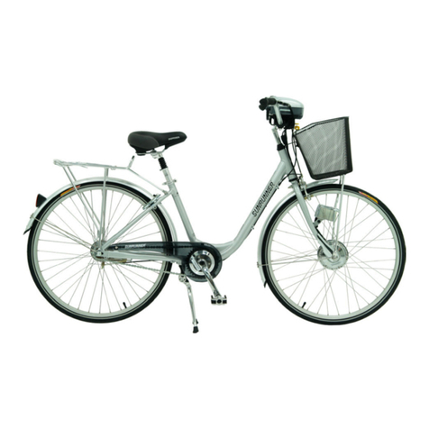
Batch Bicycles Cruiser User manual

Crafted With Purpose TM
Batch Bicycles
8889 Gander Creek Dr.
Dayton, OH 45342
833.789.8899
batchbicycles.com
PLEASE VISIT YOUR AUTHORIZED BATCH RETAILER FOR
SERVICE AND QUESTIONS.
Crafted With Purpose TM
© Batch Bicycles Ltd 2018
IBD-Cruiser EN 08-01-18 m0521
OWNER’S MANUAL
for Cruiser Bikes

Owner’sManualIndex
Safety and Warnings ...........................................................................................2-5
Assembly and Parts..............................................................................................6-15
Maintenance and Service ............................................................................ 16-21
Product ID Info.............................................................................................................22
Warranty .............................................................................................................................23
• Contact Information.............................................................Back Cover
This manual contains important safety, assembly, operation and
maintenance information.
Please read and fully understand this manual before operation.
Savethismanual for futurereference.
Alwayswear approved helmet and safety equipmentwhen using this
product.
23
BATCH Limited Warranty
We’ve Got You Covered
Batch Bicycles comes with our industry’sbest war-
ranty program – Batch Bicycles ServiceProgram.
Onceyour Batch Bicycleisregistered, Batch
Bicycles provides each original retail purchaser of a
Batch Bicycleawarranty against defects in materi-
alsand workmanship, as stated below:
General:
Partor model specicationsaresubjectto change
withoutnotice.
ThisLimited Warranty istheonly warranty for the
product. ALL WARRANTIES OTHER THAN STATED
HEREIN ARE DISCLAIMED INCLUDING IMPLIED
WARRANTIES OF MERCHANTABILITY AND FITNESS
FOR A PARTICULAR PURPOSE, TO THE EXTENT AL-
LOWABLE BY APPLICABLE LAW. ALL LIABILITY FOR
INCIDENTAL, PUNITIVE, SPECIAL, OR CONSEQUEN-
TIAL DAMAGES ARE EXPRESSLY DISCLAIMED, TO
THE EXTENT ALLOWABLE BY APPLICABLE LAW.
Theonly uses for thisproductaredescribed in this
manual.
In order to beeligiblefor serviceunder thisLimited
Warranty you MUST complete theon-linewarranty
registration within 30 daysof thedate of original
purchase of theproduct.
TheLimited Warranty extendsonly to theoriginal
consumer and isnottransferableto anyoneelse.
What does this Limited Warranty cover?
ThisLimited Warranty coversdefects in workman-
ship and materialsfor all parts of theproduct
exceptthose indicated below as notwarranted.
What must you do to keep the Limited Warranty
in eect?
This Limited Warranty is eective only if:
Productiscompletely and correctly assembled.
Productisused under normal conditionsfor its
intended purpose (see thefollowing section for
excluded activities).
Productreceives all necessary maintenanceand
adjustments.
Productisused for general transportation and
recreational use only.
What is not covered by this Limited Warranty?
Thisproductisdesigned for recreational use only.
ThisLimited Warranty does notcover normal
wear and tear, normal maintenanceitems, or any
damage, failure, or loss that iscaused by improper
assembly, maintenance, adjustment, storage, or
use of theproduct. Thislimited warranty does not
extend to futureperformance.
This Limited Warranty will be void if the prod-
uct is ever:
• Used in any competitivesport
• Used for stuntriding, jumping, aerobaticsor
similar activity
• Modied in any way
• Modied with theaddition of amotor
• Ridden by morethan oneperson at atime
• Rented, sold, or given away
• Used in amanner contrary to theinstructions
and warningsin thisOwner’sManual
What will The Manufacturer do?
Manufacturer’ssoleand exclusiveobligation under
thisLimited Warranty isto repair and/or replace, at
its soleoption, any covered defectin workmanship
or materials.
How do you get service once you have regis-
tered your product for limited warranty cover-
age as described above?
Contactyour authorized Batch Bicycles retailer.
What rights do you have?
ThisLimited Warranty gives you speci
c legal
rights. You may also haveother rights which vary
from State to State.
For how long does this Limited Warranty last?
• Steel rigid fork: Lifetimewhen owned by the
original retail purchaser.
• Aluminum Frame: Lifetimewhen owned by the
original retail purchaser.
• Any other original partor componentshall be
covered by thestated warranty of theoriginal
manufacturer. Any products notspecically
included abovearehereby omitted.
• All Batch Bicycleparts and accessories: 1 year
• All timeframes stated in thisLimited War-
ranty aremeasured from date of original retail
purchase.
When used in thisLimited Warranty, “Lifetime”
meansfor as long as theoriginal retail purchaser
ownstheproduct.
Warranty

22
Owner’s Bicycle Identication Record
NOTE: Thisinformation isonly availableon thebicycleitself.
Each bicyclehas aRecovery Codestamped
into theframe. TheRecovery Codecan
befound on thebottom of thecrank hous-
ing as shown.
Write thisnumber below to keep itfor future
reference.
If thebicycleisstolen, givethisnumber and
adescription of thebicycleto thepolice.
Thiswill help them nd thebicycle.
1
Recovery Code:
Purchase Date:
Model Name:
Product ID Info
3
3
1
2
To determine the correct size of bicycle for the rider:
• Straddletheassembled bicyclewith feet shoulder width
apartand at on theground.
• Theremust beat least 1 inch (2.5 cm) of clearance
between thehighest partof thetop tubeand the
crotch of therider with tires properly inated.
• Theminimum leg-length for therider isthehighest
partof thetop tubeplusoneinch .
• NOTE: See Assembly sectionsfor Seat adjustment.
Fitting the Rider to the Bicycle
Your Bike
IMPORTANT!! Read All Warning And Safety Information
Helmet Warning Information
WARNING:
ALWAYS WEAR YOUR HELMET
WHEN RIDING THIS PRODUCT!
• Helmet should sitlevel on your head and low on your fore-
head. Exposed forehead can resultin seriousinjury.
• Adjust thestrap slidersbelow theear on both sides.
• Bucklethechin strap. Adjust strap until itissnug.
• No morethan two ngersshould tbetween thestrap and
your chin.
• A proper tting helmet should becomfortableand notrock
forward/backward or sideto side.

4
Warning and Safety Information
The Owner’s Responsibility
WARNING: Thisbicycleismadeto beridden by onerider at atimefor general
transportation and recreational use. Itisnotmadeto withstand theabuse of stunting and
jumping.
If thebicyclewas purchased unassembled, itistheowner’sresponsibility to follow all as-
sembly and adjustmentinstructionsexactly as written in thismanual, and any “Special In-
structions” supplied and to makesureall fastenersand components aresecurely tightened.
NOTE: Periodically check that all fastenersand components aresecurely tightened.
If thebicyclewas purchased assembled, itistheowner’sresponsibility, beforeriding the
bicyclefor therst time, to makesurethebicyclehas been assembled and adjusted ex-
actly as written in thismanual, and any “Special Instructions” supplied and to makesureall
fastenersand components aresecurely tightened.
NOTE:
If product is assembled, please proceed to sections:
• Testing Stem, Handlebar
• Seat Clamp tightness.
MEANINGS OF WARNINGS:
Thissymbol isimportant. See theword “CAUTION” or “WARNING” which followsit.
Theword “CAUTION” isbeforemechanical instructions. If you do notobey these instruc-
tions, mechanical damageor failureof apartof thebicyclecan occur.
Theword “WARNING” isbeforepersonal safety instructions. If you do notobey these in-
structions, injury to therider or to otherscan occur.
• CHOKING HAZARD. Small parts. Notfor children under 3 years.
• Adultassembly isrequired.
• Handlebar hand grip or tubeend plugsshould bereplaced if damaged as baretubes have
been known to cause injury. All products with capped handlebar endsshould bechecked
regularly to ensurethat adequate protection for theendsof thehandlebarsarein place.
• Replacementforksmust havethesamerakeand tubeinner diameter as theoriginal
product.
• Do notadd amotor to theproduct.
• Do nottow or push theproduct.
• Do notmodify theproduct.
• Replaceworn or broken parts immediately with original equipment.
• If anything does notoperate properly, discontinueuse.
Warning and Safety
21
Inspection of the Bearings
Maintenance
Frequently check thebearingsof thebicycle. Haveabicycleserviceshop lubricate the
bearingsonceayear or any timethey do notpass thefollowing tests:
Head Tube Bearings
Thefork should turn freely and smoothly at all times. With thefrontwheel o theground,
you should notbeableto movethefork up, down, or side-to-sidein thehead tube.
Crank Bearings
Thecrank should turn freely and smoothly at all times and thefrontsprockets should not
beloose on thecrank. You should notbeableto movethepedal end of thecrank from
side-to-side.
Wheel Bearings
Lifteach end of thebicycleo theground and slowly spin theraised wheel by hand. The
bearingsarecorrectly adjusted if:
• Thewheel spinsfreely and easily.
• Theweightof thespokereector, when you putittoward thefrontor rear of the
bicycle, causes thewheel to spin back and forth several times.
• Thereisno side-to-sidemovementat thewheel rim when you push itto thesidewith
lightforce.
Maintenance

20
Tires
Maintenance:
• Frequently check thetireination pressurebecause all tires lose air slowly over time. For
extended storage, keep weighto of thetires.
• Do notuse unregulated air hoses to inate thetire/tubes. An unregulated hose can sud-
denly over inate tires and cause them to burst.
• Replaceworn tires.
WARNING:Do notrideor siton
theunitif atireisunder inated. Thiscan
damagethetire, inner tubeand rim.
Inating the Tires:
• Use ahand or afootpump to inate the
tires.
• Servicestation meter-regulated air hoses
arealso acceptable.
• Themaximum ination pressureisshown on thetiresidewall.
• If two ination pressures areon thetiresidewall, use thehigher pressurefor on-road riding
and thelower pressurefor o-road riding.
• Thelower pressurewill providebetter tiretraction and amorecomfortableride.
Beforeadding air to any tire, makesuretheedgeof thetire(thebead) isthesamedistance
from therim, all around therim, on both sides of thetireA. If thetiredoes notappear to be
seated correctly, release air from theinner tubeuntil you can push thebead of thetireinto
therim wherenecessary. Add air slowly and stop frequently to check thetireseating and the
pressure, until you reach thecorrectination pressure.
A
Maintenance
5
Rules of the Road
WARNING: Failureof therider to obey thefollowing “Rules of theRoad” can
resultin injury to therider or to others.
• Obey all trac regulations, signs, and signals.
• Alwayswear abicyclehelmet that meets safety standards, as well as local safety standards.
• Rideon thecorrectsideof theroad, in asinglele, and in astraightline.
• If possible, avoid riding at night, dusk, dawn and any other timeof poor visibility.
• If you must ride at night or at time of poor visibility:
• Purchase, install, and use aheadlightand taillight.
• Headlights arerequired by all states for nighttimeriding and taillights arerequired in
somestates.
• Battery-powered lights or ashing safety lights arealso recommended.
• Reectors: For your own safety, do notridethebicycleif thereectorsareincorrectly
installed, damaged, or missing. Makesurethefrontand rear reectorsarevertical. Do not
allow thevisibility of thereectorsto beblocked by clothing or other articles. Dirty reec-
torsdo notwork well. Clean thereectors, as necessary, with soap and adamp cloth.
• Makeyourself morevisibleto motorists.
• Wear light-colored or reectiveclothing, such as areectivevest and reectivebands
for your armsand legs.
• Use reectivetapeon your helmet.
• Do notlet anything cover thereectors.
• Use extra caution in wet weather:
• Rideslowly on damp surfaces because thetires will slidemoreeasily.
• Allow increased braking distancein wet weather.
• Avoid these hazards to prevent loss of control or damage to your wheels:
• Beawareof drain grates, softroad edges, gravel or sand, potholes or ruts, wet leaves, or
uneven paving.
• Cross railroad tracksat arightangleto preventtheloss of control.
• Avoid unsafeactionswhileriding.
• Do notcarry any passengers.
• Do notcarry any itemsor attach anything to your bicyclethat could hinder your vision,
hearing, or control.
• Do notridewith both handso thehandlebar.
• Do notadd amotor to theproduct.
• Do nottow or push theproduct.
• Do notmodify theproduct.
• Replaceworn or broken parts immediately with original equipment.
• If anything does notoperate properly, discontinueuse.
Warning and Safety

6
9
6
5
8
27
14
15
7
21
25
26
20
1
19 10
16
24
18
11
13
28
17
12
3
6
2
22
23
22
23
4 5
Parts Assembly View
Parts View
NOTE: All features, components
and accessories arenotincluded
on all models.
19
Maintenance
Chain Adjustment
WARNING:
• Thechain must remain on thesprock-
ets. If thechain comes o thesprock-
ets, thecoaster brakewill notoperate.
• Do notattemptchain repairs. If there
isaproblem with thechain, havea
bicycleserviceshop makeany repairs.
Adjustment:
Thechain must beat thecorrecttightness. If too tight, thebicyclewill bedicultto pedal.
If too loose, thechain can comeo thesprockets.
When thechain Cisat thecorrecttightness, you can rotate thecrank freely and you can
pull itno morethan one-half inch Aaway from astraightedgeBas shown.
Adjust the tightness of the chain as follows:
• Loosen theaxlenuts of therear wheel.
• Movetherear wheel forward or backward as necessary.
NOTE: Makesuretherear wheel isin thecenter of thebicycleframe.
• Hold thewheel in thisposition and tighten securely.
C
BA

18
Maintenance
Coaster Brakes
These modelsareequipped with arear
‘coaster’ brakethat isoperated by rotating the
crank backwards.
Operate thecoaster brakeas follows:
• Push thepedalsbackward to movethe
chain backward
• Thechain activates thecoaster brake
mechanism that isinsidetherear wheel
hub
• Asyou push thepedalsbackward with
increasing force, thebraking action of the
coaster brakeincreases.
7
Parts Assembly List
No. Description No. Description
1Frame16 Rear Fender
2FrontWheel Assembly 17 FrontReector
3FrontFender18Rear Reector
4Wheel Retainer (x2) 19 Pedal Set
5 AxleNut(x4) 20 Chain
6Fender BraceBolt(x4) 21 Fork
7Chain Guard 22 Tire(x2)
8FrontFender MountHardware23 Tube(x2)
9Rear Fender MountHardware24 Rear Wheel Assembly
10 Kickstand 25 Crank / Sprocket Set
11 GripsSet 26 Crank Bearings
12 Handlebar27Head Set Bearing
13 Handlebar Stem28Seat Post / Hardware
14 Seat
15 Seat Clamp Hardware
Parts List

8
Introduction to Assembly
ThisOwner’sManual ismadefor several dierentbicycles:
• Someillustrationsmay vary slightly from theactual product.
• Follow instructionscompletely.
• If thebicyclehas any parts that arenotdescribed in thismanual, look for separate “Special
Instructions” that aresupplied with thebicycle.
• Modelsmay havedierentaccessory itemssuch as bags, baskets, reectors, cup holders,
racks, etc.
• All features, components and accessories arenotincluded on all models.
• Use theIndex pageto locate specic sectionsof thismanual.
• Please read through thisentiremanual beforebeginning assembly or maintenance.
• If you arenotcondentwith assembling thisunit, refer to alocal bikeshop.
WARNING: Keep small parts away from children during assembly.
NOTE: All of thedirections(right, left, front, rear, etc.) in thismanual areas seen by therider
whileseated on thebicycle.
Do notdispose of thecarton and packaging until you complete theassembly of thebicycle.
Thiscan preventaccidentally discarding parts of thebicycle.
Assembly
Tools Needed (not included)
Adjustable Wrench Open-end Wrenches
Metric Allen Wrenches
17
Maintenance
Lubrication
WARNING:
• Do notover lubricate. If oil gets on thewheel rimsor thebrakeshoes, itwill reduce
brakeperformanceand alonger distanceto stop thebicyclewill benecessary. Injury to
therider or to otherscan occur.
• Thechain can throw excess oil onto thewheel rim. Wipeexcess oil o thechain.
• Keep all oil o thesurfaces of thepedalswhereyour feet rest.
• Using soap and hotwater, wash all oil o thewheel rims, thebrakeshoes, thepedals,
and thetires.
• Rinse with clean water and dry completely beforeyou ride.
• Using alightmachineoil (20W), lubricate thebicycleaccording to thefollowing table:
Lubrication Table (as equipped)
What When How
Pedalsevery six monthsPutfour dropsof oil wheretheaxles go into the
pedals.
Chain every six monthsPutonedrop of oil on each roller of thechain.
Wipeall excess oil o thechain.

16
Repair and Service
WARNING:
• Inspecttheproductfrequently. Failureto inspecttheproductand to makerepairsor
adjustments, as necessary, can resultin injury to therider or to others. Makesureall
parts arecorrectly assembled and adjusted as written in thismanual and any “Special
Instructions”.
• Immediately replaceany damaged, missing, or badly worn parts with original
equipment.
• Makesureall fastenersarecorrectly tightened as written in thismanual and any
“Special Instructions”. P arts that arenottightenough can belost or operate poorly. Over
tightened parts can bedamaged. Makesureany replacementfastenersarethecorrect
sizeand type.
NOTE: Haveabicycleserviceshop makeany repairsor adjustments for which you do not
havethecorrecttoolsor if theinstructionsin thismanual or any “Special Instructions” arenot
sucientfor you.
Maintenance
9
Assembly
Front Wheel Install:
WARNING:
• Do NOT use AxleNuts Awithoutserrationsto attach thefrontwheel.
• Ensurewheel spinsfreely withoutcontacting fork or fender.
• Failureto obey these stepscan allow thefrontwheel to loosen whileriding. Thiscan cause
injury to therider or to others.
A
B
C
1. If theAxleNuts Aarealready attached to thefrontwheel axle, begin by removing
them and Shoulder WashersBand set aside.
2. Set thewheel fully into thefrontfork Dropouts C
3. PlaceaShoulder Washer Bon each end of Axlewith small shoulder facing IN as shown.
4. Install AxleNuts Awith serrated surfacefacing IN.
5. With thewheel in thecenter of thefork and tighten both AxleNuts securely.

10
Assembly
Handlebar and Stem Installation
NOTE: Removeplastic Cap Cfrom theend of theStem D. Loosen Stem BoltEas
needed.
1. InserttheStem into theFork LocknutBup to thetop of theMIN-IN mark A.
2. Align theStem with thefronttireand tighten theStem BoltEsecurely (see Testing
Stem, nextsection)
3. If necessary, loosen theHandlebar Clamp Bolt/NutFand rotate Handlebar into a
comfortableriding position.
4. Tighten Handlebar Clamp Bolt/NutFsecurely so that Handlebar does notmovedur-
ing use.
WARNINGS:
• To preventsteering system damageand possibleloss of control, the“MIN-IN” (minimum
insertion) mark Aon thestem must bebelow thetop of theFork LocknutB.
• EnsuretheFork and Brakearepointing FORWARD beforeproceeding.
• Do notover tighten thestem bolt. Over tightening thestem boltcan damagethesteering
system and cause loss of control.
• If thehandlebar clamp in nottightenough, thehandlebar can slip in thestem. Thiscan
cause damageto thehandlebar or stem, and can cause loss of control.
D
C
E
A
B
F
15
Reector Installation (as equipped)
Reector Installation:
1. Position FRONT Reector Aso it
points straightforward.
2. Tighten Clamp Screw.
3. Position Seat Post Reector (if
equipped) Bso itpoints straight
backwards.
4. Tighten Clamp Screw.
NOTE: Do notover-tighten. Thiswill
damagetheClamp.
BA
Assembly

14
Pedal Installation
CAUTION: ThereisaRIGHT pedal marked R
and aLEFT pedal marked L.
NOTE: A Pedal Wrench ispreferred for attaching Ped-
als. A thin open-end
wrench can also beused.
• Thepedal marked Rhas right-hand threads.
Tighten itin aclockwise direction.
• Thepedal marked Lhas left-hand threads. Tighten
itin acounterclockwise direction (anti-clockwise).
• Turn therightpedal marked Rinto therightsideof
thecrank arm, and theleftpedal marked Linto the
leftsideof thecrank arm.
Tighten the pedals:
• Makesurethethreadsof each pedal arefully into
thecrank arm.
WARNING: Ensurepedalsaresecurein
crank armsso they will notloosen. Periodically check
tightness.
L
R
Three-Piece Cranks (various models)
Maintenance: Both Crank ArmsAweretightened to thespindleBat thefactory. After
riding thebicycletherst few times, makesurethecrank armshavenotloosened. If either
crank arm has loosened during this“break-in” period, re-tighten or haveittightened by a
bicycleserviceshop.
Frequently check thetightness of the
crank arms. If loose, tighten or have
them tightened by abicycleservice
shop.
WARNING: If you ride
thebicyclewith aloose crank arm, the
crank arm may fall o. Thespindle
may also damagethecrank arm.
A
B
Assembly
11
Testing Stem and Handlebar Tightness
TO TEST THE TIGHTNESS OF THE STEM:
• Straddlethefrontwheel between your legs.
• Try to turn thefrontwheel by turning thehandlebar.
• If thehandlebar and stem turn withoutturning thefront
wheel, realign thestem with thewheel and tighten the
stem bolt(s) tighter than before(about1/2 revolution
only at atime).
• Do thistest again, until thehandlebar and stem do not
turn withoutturning thefrontwheel.
TO TEST THE TIGHTNESS OF THE HANDLEBAR CLAMP:
• Hold thebicyclestationary and try to movetheendsof
thehandlebar up and down.
CAUTION: Do notexceed 100 lbs(45 kg) downward
force.
• If thehandlebar moves, loosen thebolt(s) of the
handlebar clamp.
• Putthehandlebar in thecorrectposition and tighten thebolt(s) of thehandlebar
clamp tighter than before.
• If thehandlebar clamp has morethan onebolt, tighten thebolts equally.
• Do thistest again, until thehandlebar does notmovein thehandlebar clamp.
Assembly

12
Assembly
WARNING: To preventtheSeat
coming loose and possibleloss of control, the
“MIN-IN” (minimum insertion) mark Aon the
Seat Post must beBELOW thetop of theSeat
TubeB.
STEP 1 INSERT SEAT POST INTO SEAT
TUBE:
• If needed, loosen Seat Post Clamp Screw D.
• PointtheSeat forward and puttheSeat Post
Cinto theSeat TubeBwith the“MIN-IN”
marksBELOW thetop of theSeat Tubeas
shown.
STEP 2 BOLT SEAT CLAMP:
• With Seat Post Cinserted according to
STEP 1 - Tighten Screw Dsecurely so Seat
supports therider withoutmoving.
Seat Installation
A
A
D
1
2
C
B
C
13
Testing Seat Clamp and Post Clamp Tightness
To test the tightness of the seat clamp and the post clamp:
• Try to turn theseat side-to-sideand to movethefrontof theseat up and down.
• If the seat moves in the Seat Clamp:
• Loosen theSeat Clamp Nut.
• Puttheseat in thecorrectposition and tighten theSeat Clamp tighter than before.
• Do thistest again, until theseat does notmovein theSeat Clamp.
• If the Seat Post moves in the Seat Tube Clamp:
• Loosen theSeat Clamp Lever.
• PuttheSeat Post in thecorrectposition and tighten theSeat Clamp Nuttighter than
before.
• If necessary, tighten or loosen Hand Nutso that Quick Release tightenssecurely.
• Do thistest again, until theSeat Post does notmovein theSeat TubeClamp.
Seat Bolt Saddle Adjustment (various models)
SINGLE BOLT CLAMP:
1. Loosen theClamp BoltAsuciently to allow
any SerrationsBon themechanism to disen-
gagebeforechanging thesaddle’sangle.
2. With serrationsfully re-engaged and saddlein a
comfortableriding position, tighten theClamp
BoltAsecurely to ensurethesaddlewill not
comeloose.
WARNING: Serrationson themat-
ing surfaces of theClamp can wear with use and
adjustment. Check that theClamp istightand
securebeforeeach ride.
DUAL CLAMP:
3. Loosen Clamp Bolt/NutCas needed and
adjust Seat to acomfortableriding position.
4. With Clamp fully on Seat Post as shown, tighten
Bolt/NutCsecurely so that seat does not
movewhen in use.
A
C
B
Assembly
Table of contents


