BirdBike A-Frame User manual
USER MANUAL
A-Frame & V-Frame User Manual
Please read this manual very carefully before using the
product. The manual contains important instructions for
the safe use and longevity of your bike.
If you need any type of support or warranty information for
your BirdBike, please contact us before returning it back to
wherever you purchased it. The BirdBike Support Te am is
ready to help you via phone or email and you can also visit
support.bird.co for more info.
Phone:1-888-309-3702 (M-F 9a-5p EST)
Email: BirdBike@bird.co
Web: support.bird.co
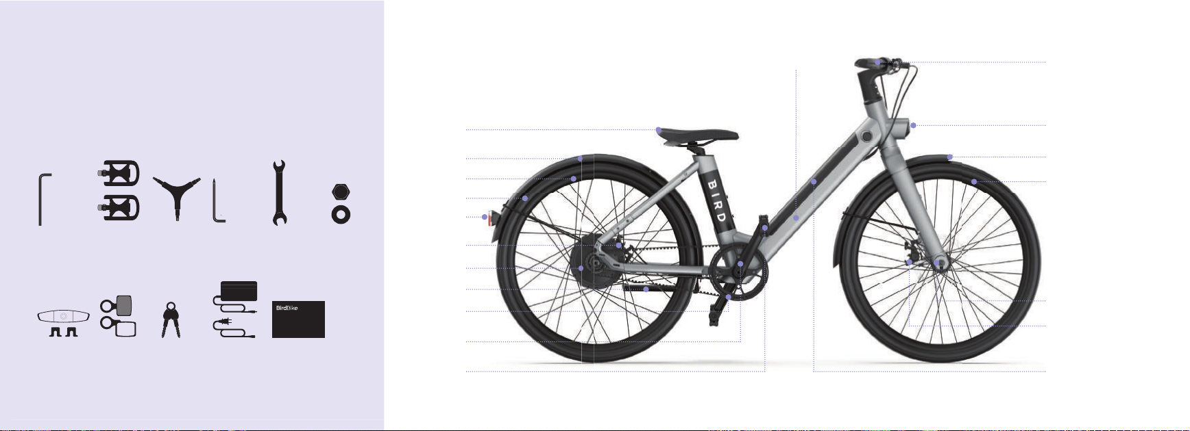
AFRAME

Pedal
Crank
Kickstand
Front sprocket
Rear disc brake
Motor
Rear rim
Rear fender
Tail light
Saddle
Tire
AFRAME
To prepare for the assembly of your BirdBike, first take out all
pieces of the BirdBike from the box and remove all
packaging. Also, open the accessory box and remove all
tools, parts and everything else that’s inside of it.
Assembly Prep1
Pedals
(x 2)
Wheel Reflectors
(x 2) and
fasteners (x 2)
2.5 mm
Allen key
3mm / 4mm /
5mm Y-wrench
L-key Phillips
Screwdriver
Rear and Front
Reflectors
Battery Keys Power Supply
and Cable
13mm / 15mm
Two-sided
Wrench
Cap nut and
washer
This Manual
4
Front light
HandlebarFrame
Front fender
Front rim
Fork
Front disc brake
Battery

AFRAME
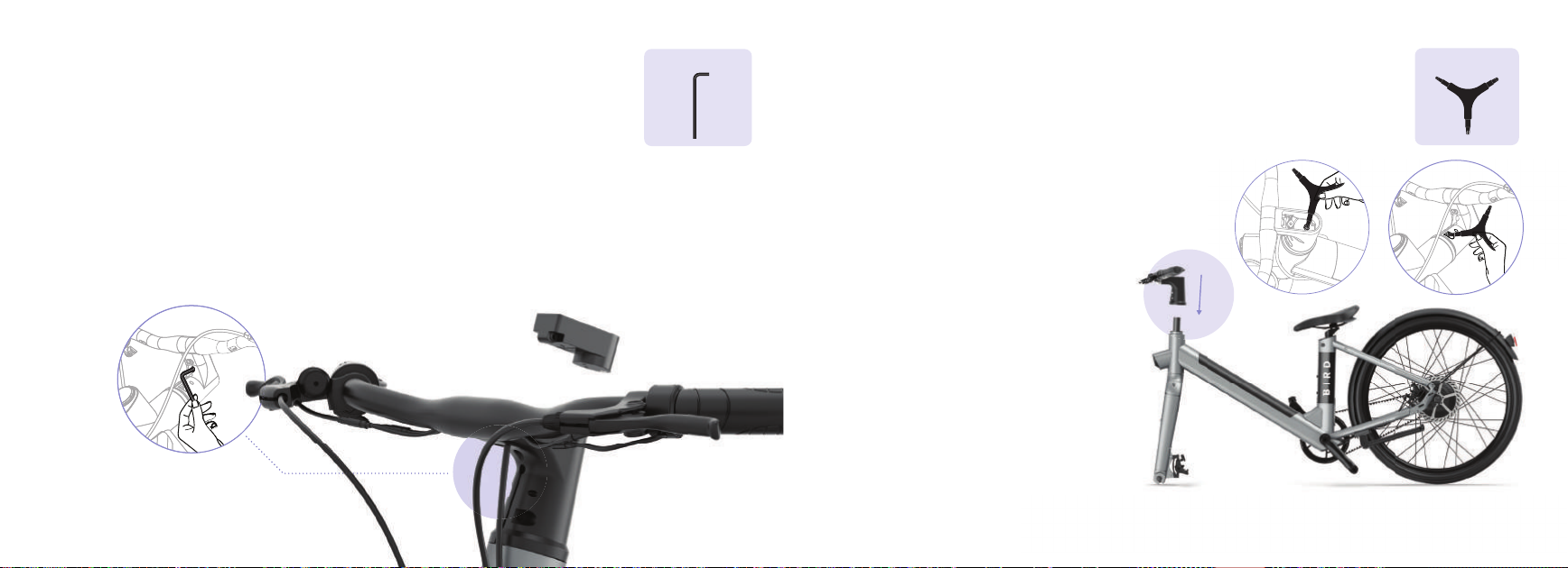
Install the handlebar2
Remove Display from the Handlebar
Use the 2.5mm Allen Key to remove the screw that’s behind
the display on the handlebar. If the display isn’t easily removed
from the handlebar, use the hex key to gently push it from the
back of the handlebar through the hole from where the screw
was removed.
2.5 mm Allen key
VFRAME
Y-wrench
6
Install the Handlebar
Use the 5mm end of the Y-wrench to remove
the hex bolt from inside the steerer tube and
insert the handlebar over the steerer tube.
After the handlebar is installed and lined up
properly with the tire and frame, insert the
hex bolt through the handlebar and into the
steerer tube.
Use the 5mm end of the Y-wrench to gently
tighten the hex bolt into the handlebar so that
there’s no play between the fork and frame.
Finally, make sure the handlebar, frame, and
front wheel are still aligned and tighten the
two steering stem screws with the 5mm end
of the Y-wrench so the handlebar stays
in place.
Y-wrench
3
AFRAME
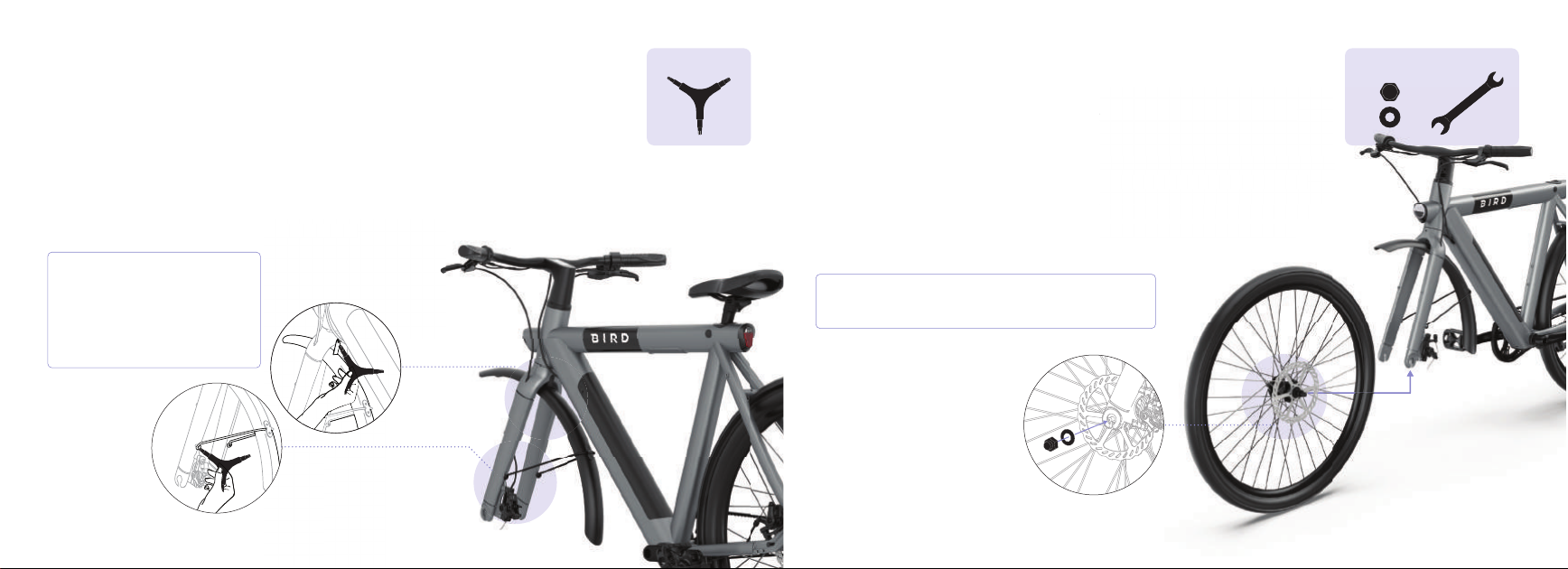
Attach the front fender
Attach the front fender to the fork by using the screws that are already in the fork legs.
Use the 4mm end of the Y-wrench to remove the two screws from the fork legs and then
tighten the screws through the holes at the end of the fender mounts.
Using the 4mm end of the Y-wrench remove the screw that’s on the top of the backside
of the fork and tighten the screw through the fender mount bracket on top of the fender
so that it’s secured tightly to the back of the fork.
ac
k
o
f
t
h
e
f
or
k
.
When tightening the fender, avoid
rubbing the Y-wrench on the
frame so the paint doesn’t get
scratched. Also, don’t over
tighten the screws to avoid
stripping the holes.
WrenchCap Nut and
Washer
Install the front wheel4
Be sure to remove the plastic front rotor protector from the front wheel axle
before starting this step.
Align the front wheel axle so that it’s inside of the fork slots on both sides. The side
with the brake rotor should be aligned so that it fits inside the front disc brake.
Once the fork slots are sitting on both sides of the axle, install washers at both
ends and tighten up the cap nuts on the outside using the 15mm end of the
wrench.
ector
f
rom t
h
e
f
ront w
h
ee
l
ax
l
e
f
t
h
e
f
or
k
s
l
ots on
b
ot
h
si
d
es. T
h
e si
d
e
t it
f
its insi
d
e t
h
e
f
ront
d
isc
b
ra
k
e.
of
t
h
e ax
l
e, insta
ll
was
h
ers at
b
ot
h
s
i
d
e using t
h
e 15mm en
d
o
f
t
h
e
8
After installing the front wheel, extend the kickstand for
better stability and easier assembly during the next steps.

Adjust the saddle5
AFRAME
Remove the cap that’s covering the seat clamp screw, which is located just
below the seat.
Insert the seat post into the seat tube. To adjust the height, move it to where
it feels comfortable, then tighten the seat clamp screw with the 5mm end
of the Y-wrench. Be sure to replace the cap once the seat post is set and
tightened.
Warning: do not extend the seat post
farther than the minimum insertion line
that is indicated on the seat post.
wh
ic
h
is
l
ocate
d
j
ust
gh
t, move it to w
h
ere
w
it
h
t
h
e 5mm en
d
a
t post is set an
d
Y-wrench Attach the pedals6
10
L R
Install the left and right pedals by screwing them into the crank.
Pay attention to which pedal is being installed on the left and
the right as the left pedal is reverse threaded so it is tightened
counter-clockwise. You can tell the two pedals apart by looking
for the “R” on the right pedal and “L” on the left.
After the pedals are screwed on by hand, use the 15mm end of
the wrench to give the pedals a final tightening.
PedalsWrench
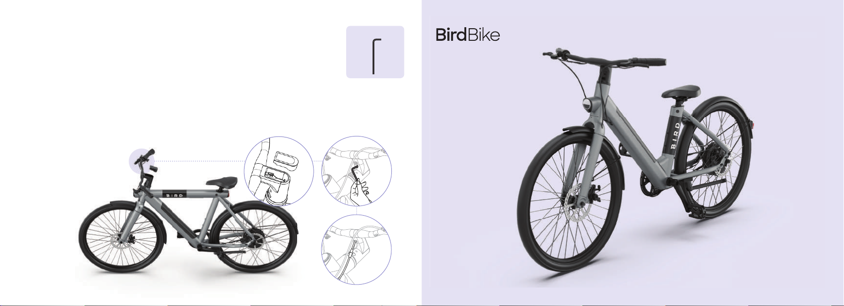
Install the display72.5 mm Allen key
For the final step before powering on your BirdBike, reinstall the display back into
the handlebar so that the Bird logo is at the bottom. Be sure to not pinch the cable
inside of the handlebar while reinstalling. Once reinstalled, use the 2.5mm Allen key
to replace and tighten the screw under the display so that it’s tightened into place
inside of the handlebar.
Connect the one end of the power cable coming from the bottom of the display
to the other end of the power cable that is coming out of the bottom of the frame.
At this point you can power on your BirdBike, but be sure to read through the rest
of this manual before riding.
VFRAME
V
F
RAM
E
12
AFRAME
To prepare for the assembly of your BirdBike, first take out all
pieces of the BirdBike from the box and remove all
packaging. Also, open the accessory box and remove all
tools, parts and everything else that’s inside of it.
Assembly Prep1
Pedals
(x 2)
Wheel Reflectors
(x 2) and
fasteners (x 2)
2.5 mm
Allen key
3mm / 4mm /
5mm Y-wrench
L-key Phillips
Screwdriver
Rear and Front
Reflectors
Battery Keys Power Supply
and Cable
13mm / 15mm
Two-sided
Wrench
Cap nut and
washer
This Manual
Pedal
Crank
Kickstand
Front Sprocket
Rear disc brake
Motor
Rear rim
Rear fender
Saddle
Tire
Tail light
14
Front light
HandlebarFrame
Front fender
Front rim
Fork
Front disc brake
Battery
Install the handlebar2
VFRAME
Remove Display from the Handlebar
Use the 2.5mm Allen Key to remove the screw that’s behind
the display on the handlebar. If the display isn’t easily removed
from the handlebar, use the hex key to gently push it from the
back of the handlebar through the hole from where the screw
was removed.
2.5 mm Allen key
VFRAME
Install the Handlebar
Use the 5mm end of the Y-wrench to remove
the hex bolt from inside the steerer tube and
insert the handlebar over the steerer tube.
After the handlebar is installed and lined up
properly with the tire and frame, insert the
hex bolt through the handlebar and into the
steerer tube.
Use the 5mm end of the Y-wrench to gently
tighten the hex bolt into the handlebar so that
there’s no play between the fork and frame.
Finally, make sure the handlebar, frame, and
front wheel are still aligned and tighten the
two steering stem screws with the 5mm end
of the Y-wrench so the handlebar stays
in place.
Y-wrench
16

VFRAME
Y-wrench
3Attach the front fender
Attach the front fender to the fork by using the screws that are already in the fork legs.
Use the 4mm end of the Y-wrench to remove the two screws from the fork legs and then
tighten the screws through the holes at the end of the fender mounts.
Using the 4mm end of the Y-wrench remove the screw that’s on the top of the backside
of the fork and tighten the screw through the fender mount bracket on top of the fender
so that it’s secured tightly to the back of the fork.
When tightening the fender, avoid
rubbing the Y-wrench on the
frame so the paint doesn’t get
scratched. Also, don’t over
tighten the screws to avoid
stripping the holes.
WrenchCap Nut and
Washer
Install the front wheel4
Be sure to remove the plastic front rotor protector from the front wheel axle
before starting this step.
Align the front wheel axle so that it’s inside of the fork slots on both sides. The side
with the brake rotor should be aligned so that it fits inside the front disc brake.
Once the fork slots are sitting on both sides of the axle, install washers at both
ends and tighten up the cap nuts on the outside using the 15mm end of the
wrench.
Wrench
Cap
Nut
and
Wash
e
r
h
e
e
l
o
tector
f
rom t
h
e
f
ront w
h
ee
l
ax
l
e
o
f
t
h
e
f
or
k
s
l
ots on
b
ot
h
si
d
es. T
h
e si
d
e
h
at it fits inside the front disc brake.
s
o
f
t
h
e ax
l
e, insta
ll
was
h
ers at
b
ot
h
u
tside using the 15mm end of the
18
After installing the front wheel, extend the kickstand for
better stability and easier assembly during the next steps.

Attach the pedals5
L
R
PedalsWrench
Install the left and right pedals by screwing them into the crank.
Pay attention to which pedal is being installed on the left and
the right as the left pedal is reverse threaded so it is tightened
counter-clockwise. You can tell the two pedals apart by looking
for the “R” on the right pedal and “L” on the left.
After the pedals are screwed on by hand, use the 15mm end of
the wrench to give the pedals a final tightening.
Install the display62.5 mm Allen key
20
For the final step before powering on your BirdBike, reinstall the display back into
the handlebar so that the Bird logo is at the bottom. Be sure to not pinch the cable
inside of the handlebar while reinstalling. Once reinstalled, use the 2.5mm Allen key
to replace and tighten the screw under the display so that it’s tightened into place
inside of the handlebar.
Connect the one end of the power cable coming from the bottom of the display
to the other end of the power cable that is coming out of the bottom of the frame.
At this point you can power on your BirdBike, but be sure to read through the rest
of this manual before riding.

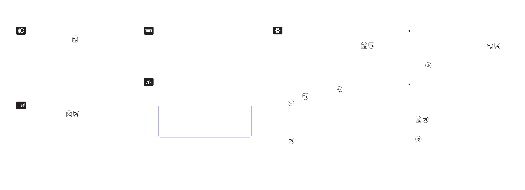
FUNCTIONS OVERVIEW
Power button
Battery capacity display
Switch between
mph and km/h
Assist level
Mileage display
Speed
display
Walk mode
Head light
Error warning
+ button
- button
22
After pressing and holding the - button
for 2 seconds the BirdBike will go into Walk
Mode. The display will show the push
symbol and you will receive
power-assistance while pushing the
BirdBike in more difficult situations, like
going uphill. When you release the button,
Walk Mode will automatically turn off.
POWER ONOFF
Operating Options
DISPLAY INTERFACE
After long pressing the power button,
the BirdBike will be turned on. While the
power is on, press and hold the power
button again to turn off the power.
After the BirdBike is turned on, the display
defaults to showing real-time speed and
total distance traveled (miles or km). With a
short press of the power button you
can toggle through the total distance
(miles/km) and single trip distance
(miles/km).
The power will automatically shut off after 5
minutes if not being used.
WALK MODE
The power-assisted Walk Mode function
should only be used while pushing the
electric vehicle and never used while riding.
TURN ONOFF THE HEADLIGHTS
Press and hold the + key for 2 seconds
to turn on the headlight. When the
headlight is on, the display brightness will
also automatically dim. Whenever natural
lighting is insufficient (such as in bad
weather) or when riding in the dark, you
should always turn on the headlight. Press
and hold the + keyagain for 2 seconds to
switch off the headlight.
BATTERY LEVEL
When the battery is full, the five-segment
battery icon will be fully lit and the number
of bars will decrease as the battery level
decreases. When the battery is low and
needs charging, the battery icon will flash.
ASSIST LEVEL
Short press the + / - buttons to
switch the assist level of the BirdBike and
change the output power of the motor.
Level 0 is no assistance, and level 5 offers
the highest amount of assist. The default
level when the BirdBike is first turned on is
level 5, and each subsequent time it will
default to the last assist level that was used.
ERROR CODE DISPLAY
Error code display: For more information on
error codes, please visit support.bird.co.
When an error code is displayed, please
troubleshoot or contact BirdBike support as
soon as possible as the BirdBike will not be
able to be ridden normally until the error is
resolved.
24
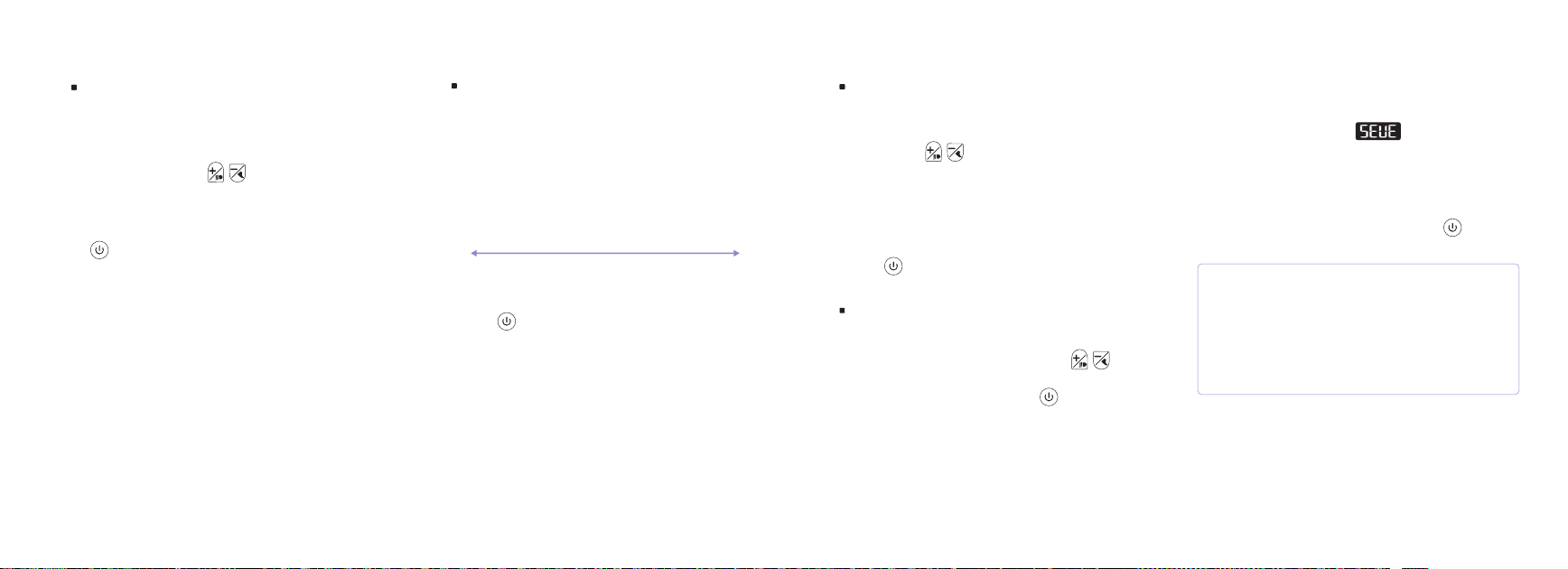
To enter Settings Mode first power on the
BirdBike, then long press and hold
keys +/- at the same time. Once in Settings
Mode you adjust from mph to km/h, set a
speed limit, set wheel diameter, and adjust
the brightness of the display.
While In Settings Mode, you can toggle up
and down with the up (+) and
down (-) buttons. Short press the
power button to adjust the ítem you
want to change, then short press the
power button after making your selection
to save.
To exit Settings Mode just long press the
- button for 2 seconds. Also, while in
Settings Mode if no operation is performed
for 30 seconds, then the display will return
back to normal.
When P2 is displayed in the speed position
while in Settings Mode and the speed limit
value is displayed in the trip position, you
can then adjust the speed limit with the
+/- buttons. The minimum is 7 mph
(12km/h) and the maximum is 20mph
(32km/h). After selecting, short press the
power button to save.
SETTINGS MODE
When P1 is displayed in the speed position
while in Settings Mode, press the
+/- buttons to switch the display between
mph or km/h. After selecting, short press
the power button to save.
MPH & KMH P1
SPEED LIMIT P2
When P3 is displayed in the speed position
while in Settings Mode, the wheel diameter
setting will be shown in inches and can be
adjusted with the +/- buttons.Be
sure to know the proper sizes as selecting
the wrong size can result in unexpected
speeds. After selecting, press the
power button so save.
DISPLAY BRIGHTNESS P4
When P4 is displayed in the speed position
while in Settings Mode, the display
brightness settings from 1 to 5 are displayed
according to the current setting. 1 is the
lowest brightness setting, and 5 is the
highest (default setting is 5).
After the setting is completed, short press
the power button to save.
DARK BRIGHT
12345
WHEEL DIAMETER P3
2626
When P5 is displayed at the speed position
while in Settings Mode, choose 0-9 by
using the +/- buttons, which
represents the automatic shutdown time in
minutes. The default setting to power off
automatically after 5 minutes and setting
the timer to 0 means that auto power off
will be disabled. After selecting, short press
the power button to save.
AUTOMATIC POWER OFF TIMER P5 SERVICE REMINDER:
After the BirdBike has been ridden 300 miles
(500km), there will be a service
inspection reminder shown on the display the
next time it’s turned on. If the reminder isn’t
marked as complete, then it will be displayed
every time the vehicle is turned on. The reminder
can be cleared by a short press of the power
button.
To remove the service reminder completely until the
next 300 miles (500km), the rider must connect to
the BirdBike through the Bird App and mark the
service inspection as complete. Once marked
complete in the Bird App, the service reminder will
then no longer be displayed by default each time the
BirdBike is powered on.
When P6 is displayed at the speed position
while in Settings Mode, press the +/-
buttons to select either Y or N. After
selecting Y, short press the power
button to reset the trip meter to 0. After
resetting the trip meter, short press the
power button to save the parameters.
RESET TRIP METER P6

Operation and Safety Instructions
For your personal safety, you must pay attention to the following
safe use of the BirdBike:
• It is recommended to always wear a helmet when riding.
• Do not exceed the maximum load of 265 lbs (120.2 kg) and no
more than one rider at a time.
• When riding in rain or snow, it will take longer to slow the
vehicle, so be aware of braking earlier than normal.
• Try to avoid riding in severe weather, such as heavy rain,
snow, or wind.
For your personal safety, you must pay attention to the following
safe use of electric bicycles:
• Do not park the BirdBike in building halls, evacuation stairs, or
walkways.
• Do not charge or park the BirdBike in residential buildings.
Keep away from combustibles when charging, and do not
leave charging for an extended period of time.
The battery should be used and maintained correctly in
accordance with the method required by this manual. The
battery should not be disassembled without authorization
and should be recycled by professional experts.
• The charger should be used and maintained correctly in
accordance with the method required by this manual.
• Carefully read the warning labels and instructions of the
charger before use. When replacing the charger, it should be
purchased from Bird only.
• Before washing the ebike, you should read and understand
the part of the manual about the "Precautions for washing".
• When adjusting the handlebars or saddles, care should be
taken not to expose the safety marks of the handlebars and
saddles.
• Always check your BirdBike before riding. If there are any
issues found, please seek professional assistance with
solving the issue or repair.
• Always check whether the front and rear brakes work
normally.
• Always check that handlebars, front and rear wheels, and all
other parts of the BirdBike are tightened properly.
Precautions while riding:
• Pay attention and observe all pedestrians, vehicles,
obstacles, and others using the road at all times.
READ BEFORE RIDING
28
• Do not drive under the influence of alcohol.
• Anyone who suffers from diseases such as hypertension,
hernia, concussion, epilepsy, and cardiovascular disease
should not ride the BirdBike.
• Do not follow motor vehicles too closely (because they may
slow down or turn at any time), and always pay attention to
the brakes.
• Do not touch things on the road with your feet while riding.
• While riding at high speed, be sure to brake the bike slowly,
and do not brake suddenly under any circumstances.
• When driving at night, slow down, drive with caution and use
the lights of the vehicle.
• Try to ride in designated bicycle lanes or the edge of the
road, in the direction of traffic flow.
• Stop at stop signs, slow down and watch traffic at
intersections.
• Jackets, boots, trousers, gloves, etc. are effective protective
clothing to prevent abrasions if an accident were to occur
while riding. It is recommended to wear them to protect
yourself.
• •Do not wear loose clothing to avoid the risk of
entanglementin the moving parts of the BirdBike.
• Please wear appropriate safety equipment according to the
type of riding you plan to do. It is best to wear a pair of sports
sunglasses, which can reduce the damage of ultraviolet rays
to the eyes and protect the eyes from tree branches and
flying rocks or stones.
• Please perform regular maintenance and inspection of your
BirdBike.
• Please do not replace any parts by yourself to avoid damage.
• If any parts are damaged while riding that affect safety,
please stop riding immediately.
• You should not listen to music while riding (because when
you listen, it distracts your attention, and you cannot hear the
sound of horns or other sounds of motor vehicles, which is
very dangerous)
• If you have any problems while riding, please resolve the
problem if possible or contact Bird support for help.
Precautions for washing the BirdBike:
• When washing the BirdBike, do not directly pour water on
the motor and the front and rear axles to prevent water from
affecting the performance and life of the product. When
washing the BirdBike, do not use a strong steam or
high-pressure water spray.
• After washing the vehicle or riding through water, pay special
attention to the working conditions of the brakes.The braking
capability may be reduced in these circumstances.

Maintenance and general troubleshooting
Inspection of handlebar and front & rear wheel:
• Move the BirdBike up, down, front, back, left and right to check
whether the handlebars and the axle nuts of the front and rear
wheels are tightened properly, whether the handlebars are
tightened properly, and whether there is any abnormal
rubbing or damage happening between parts
• Push the vehicle back and forth to check whether the front
and rear wheels rotate smoothly and without any abnormal
noise or rubbing.
• Carefully check the entire vehicle before riding and if you find
any issues, please contact a professional for repair or contact
Bird support for help.
Inspection of power circuit and lighting circuit
• Turn on the power, operate the lighting switch, check whether
the headlights and taillights are on, and if they are at normal
levels.
• Check for any damage with the lighting system.
• Check whether the power cables on the BirdBike are
connected and are operating safely as intended as well as
whether all connectors are functioning properly.
Inspection of front and rear brakes
• Adjustment of the brake lever: Pinch the front and rear brake
levers, and confirm whether the brakes are working when the
distance between the brake lever and the handlebar is ½ inch.
• Adjustment method of the front and rear brakes: The distance
between the brake and the brake lever is specified to be
between 10-20mm.
• When the brake is in a tightly gripped state, the brake pad and
the brake disc should be contacting evenly.
• The brake pads and brake discs should be replaced at the
same time (the adjustment of the rear wheel brake is the
same as that of the front wheel brake).
Battery installation status
• Confirm that the battery is in a fixed state, connected, and
operating properly.
30

BirdBike Limited Manufacturer’s Warranty
The BirdBike comes with a limited manufacturer’s warranty
and is covered from any defects or issues that are outside of
normal wear & tear within the warranty period and terms
outlined at support.bird.co.
Do not modify the BirdBike as it will void your warranty and
introduce potential safety issues. Read and understand all safety
warnings listed on the product label and in this manual.
Proof of purchase must be verified before any warranty claim is
filed.
Warranty terms only apply to the original owner.
If you need any type of support or warranty information for your
BirdBike, please contact us before returning it back to wherever
you purchased it. The BirdBike Support Team is ready to help you
via phone or email and you can also visit support.bird.co for more
info.
Phone: 1-888-309-3702 (M-F 9a-5p EST)
Email: BirdBike@bird.co
Web: support.bird.co
32
FCC Statement
This device complies with Part 15 of the FCC rules. Operation is
subject to the following two conditions: 1) this device may not
cause harmful interference, and 2) this device must accept any
interference received, including interference that may cause
undesired operation.
This equipment has been tested and found to comply with the
limits for a Class B digital device, pursuant to Part 15 of the FCC
rules. These limits are designed to provide reasonable
protection against harmful interference in a residential
installation. This equipment generates, uses and can radiate
radio frequency energy and if not installed and used in
accordance with the instructions, may cause harmful
interference to radio communications. However, there is no
guarantee that interference will not occur in a particular
installation. If this equipment does cause harmful interference to
radio or television reception, which can be determined by
turning the equipment off and on, the user is encouraged to try
correct the interference by one or more of the following
measures:
-Reorient the receiving antenna.
-Increase the separation between the equipment and receiver.
-Connect the equipment into and outlet on a circuit different
from that to which the receiver is connected.
-Consult the dealer or an experienced radio/TV technician for
help.
Changes or modifications not expressly approved bythe party
responsible for compliance could void your authority tooperate
the equipment.

ISED Statement
This device contains licence‐exempt transmitter(s)/receiv-
er(s) that comply with Innovation, Science and Economic
Development Canada’s licence‐exempt RSS(s). Operation is
subject to the following two conditions: (1) This device may not
cause interference. (2) This device must accept any
interference, including interference that may cause undesired
operation of the device.
ADVERTENCIA IC Cet appareil contient des émetteurs /
récepteurs exemptés de licence conformes aux RSS
(RSS)d'Innovation, Sciences et Développement économique
Canada. Le fonctionnement est soumis auxdeux conditions
suivantes : (1) Cet appareil ne doit pas causer d'interférences.
(2) Cet appareil doit accepter toutes les interférences, y
compris celles susceptibles deprovoquer un fonctionnement
indésirable de l'appareil.
This device complies with ISED RF radiation exposure limits set
forth for an uncontrolled environment.
Prop 65 Warning
This product can expose you to chemicals including chromium,
which is known to the State of California to cause cancer and
birth defects or other reproductive harm.
For more information go to: http://www.p65warnings.ca.gov.
34

Questions? We’ve got answers.
Visit support.bird.co for more info.
Phone: 1-888-309-3702 (M-F 9a-5p EST)
Email: BirdBike@bird.co
This manual suits for next models
1
Table of contents
Other BirdBike Bicycle manuals


