Bathology Spectrum 620-C User manual
Color Light Salt Panel
Installation and Operation Manual
Spectrum 620-C & 626-C

2
Spectrum 620-C & 626-C
ContentsContents
Installation ConsiderationsInstallation Considerations-------------------------------------------------
Installation- OverivewInstallation- Overivew -------------------------------------------------------
Installation- Himalayan Salt Panel (Interior (Phase 1))Installation- Himalayan Salt Panel (Interior (Phase 1))-------------
Installation- Himalayan Salt Panel (WIFI (Phase 1))Installation- Himalayan Salt Panel (WIFI (Phase 1))-----------------
Installation- Himalayan Salt Panel (Remote (Phase 1))Installation- Himalayan Salt Panel (Remote (Phase 1))-------------
Installation- Himalayan Salt Panel (Phase 2)Installation- Himalayan Salt Panel (Phase 2)--------------------------
Operation - InteriorOperation - Interior------------------------------------------------------------
Installation- Himalayan Salt Panel (WIFI (Phase 3))Installation- Himalayan Salt Panel (WIFI (Phase 3))-----------------
Operation - WIFIOperation - WIFI----------------------------------------------------------------
Installation- Himalayan Salt Panel (Remote (Phase 1))Installation- Himalayan Salt Panel (Remote (Phase 1))-------------
Operation - RemoteOperation - Remote------------------------------------------------------------
SpecificationsSpecifications-------------------------------------------------------------------
Replacement PartsReplacement Parts------------------------------------------------------------
NotesNotes------------------------------------------------------------------------------
33
44
1010
1111
1212
1414
1515
1616
1717
1818
1919
2020
2020
2121
3
by
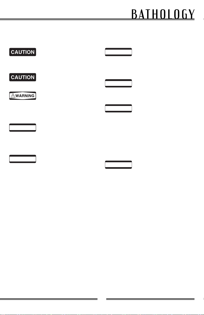
Installation ConsiderationsInstallation Considerations
Please read this manual in its entirely prior to installationPlease read this manual in its entirely prior to installation
Carefully review all
installation options and instructions
before proceeding.
For safety purposes, use
safety goggles at all times.
If there is any risk of
uninsulated electrical connections in
your wall / ceiling area, use insulating
gloves.
Prior to installation,
consider the placement carefully,
taking into account the location of
electrical, plumbing, and other fixture.
The Spectrum 620-C and
626-C require a minimum of 4” at both
ends to insert or remove center salt
block for mounting or removing panel.
Power Supplies and
Receivers should be installed outside
of the bathing environment. Do not
install in Sauna Environment.
It is recommended that
all electrical equipment be tested prior
to installation.
The Spectrum 623
wall mounted interior control can
be installed outside of the Sauna
environment, 48” above the floor, on a
vertical wall, convenient for operation.
It can also be installed inside the Sauna
environment, 36” above the floor
maximum.
Each Salt Panel Assembly
may weigh up to 55 lbs and require
additional framework or support. 3/4”
Plywood is recommended to help
support the weight of the fixture(s).
! IMPORTANT
! IMPORTANT
! IMPORTANT
! IMPORTANT
! IMPORTANT
! IMPORTANT

4
Spectrum 620-C & 626-C
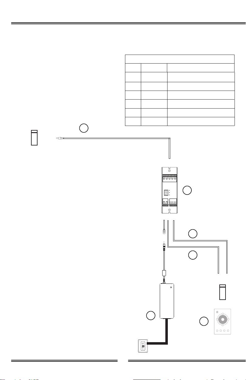
InstallationInstallation -- OverviewOverview
Package Includes
Item Quantity Description
A 1 Himalayan Salt Panel
Assembly (Salt Pre-Installed)
B 4 Himalayan Salt Blocks
C 4 Mounting Screws (10x2-1/2)
D 4 Trim Boards (not shown)
Item Quantity Description
A 1 Himalayan Salt Panel
Assembly (Salt Pre-Installed)
B 4 Himalayan Salt Blocks
C 4 Mounting Screws (10x2-1/2)
D 4 Trim Boards (not shown)
Spectrum 620-C Spectrum 626-C
Himalayan Salt
Panel Assembly
Himalayan Salt
Blocks (Pre-Installed)
Sauna Environment
Himalayan
Salt Blocks
Mounting Screws
(10x2-1/2)
A
B
C
Additional 3/4”
Plywood Framework
Electrical Box
(by others)
Note: It is recommended that all electrical equipment be tested prior to installation.
Note: Illustration below showcases Spectrum 620-C Humalayan Salt Panel Assembly
which measures 48x12. Spectrum 626-C operates similarly, but measures 16x16. Surface
mount shown.

5
by
Note: Control is required to operate this system.
For details on those controls, please see the following:
Spectrum 623 - Wall Mounted Interior Control: Page 6
Spectrum 625 - WIFI / Alexa: Page 8
Spectrum 631 - Remote (Color): Page 8
6
Spectrum 620-C & 626-C
Dry, Accessible
Location
Package Includes
P B
C
S
1 2 3 4
Electrical Box
(by others)
Electrical Box
(by others)
Item Quantity Description
E 1 Light Extension Cable
F 1 DMX Decoder
G 1 Power Supply
H 1 DMX Cable
I 1 Power Connector
J 1 Touch Interface
Spectrum 623 - Interior
Grounded 120VAC,
20 Amp Circuit
Power Supply
DMX Decoder
DMX Cable
Power
Connector
Touch Interface
Light Extension
Cable
G
F
H
I
J
E
GND
V+ V+
R -
OUTPUT
DC INPUT
G -
B -
W -
V -
DMX+
DMX -
DMX+
DMX -
GND
V+ V+
R -
OUTPUT
DC INPUT
G -
B -
W -
V -
DMX+
DMX -
DMX+
DMX -
7
by
Spectrum 623 - Interior
Power Supply Touch Interface
V+
V+
Black
Black Red
Red
Green
Blue
R G B
V+
GND
V - V -
DMX+
DMX -
DMX Decoder
Light Extension
Cable
G
F
J
E

8
Spectrum 620-C & 626-C
Item Quantity Description
E 1 Light Extension Cable
F 1 WIFI Receiver / Bracket
G 1 Power Supply
H 4 Wire Nut
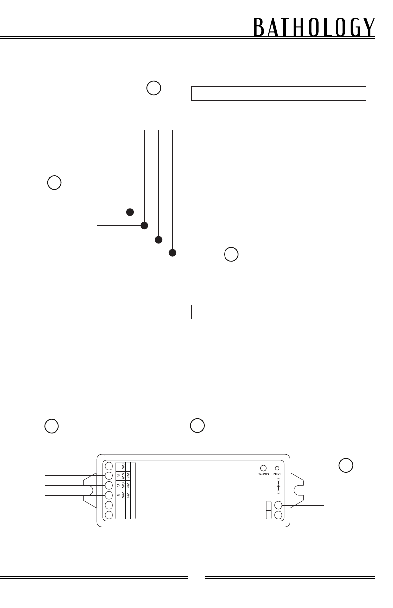
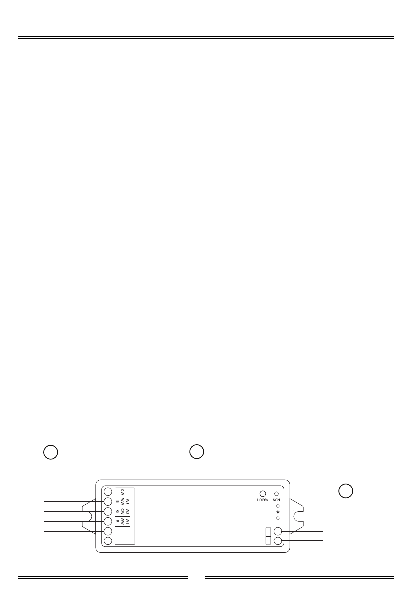
Spectrum 625 - WIFI / Alexa
Spectrum 631 - Remote (Color)
Item Quantity Description
E 1 Light Extension Cable
F 1 RF Receiver
G 1 Power Supply
H 1 Remote Control (Color)
Grounded 120VAC,
20 Amp Circuit
Dry, Accessible
Location
Light Extension
Cable Power Supply
WIFI Receiver
EG
F
Grounded 120VAC,
20 Amp Circuit
Dry, Accessible
Location
Remote Control
(Color)
Power Supply
H
G
Light Extension
Cable
E
RF Receiver
F
W
W4
+
-
OUTP UT
+
INPUT
12-24VDC
+
+
+
+
+
+
Electrical Box
(by others)
Electrical Box
(by others)
9
by
Spectrum 625 - WIFI / Alexa
Spectrum 631 - Remote (Color)
RF Receiver
F
W
W4
+
-
OUTPU T
+
INPUT
12 -24VDC
+
+
+
+
+
+
V+
V+
B
R
R
G
G
G
R
B
B
V+
V+
V -
WIFI Receiver
Light Extension
Cable
Wire Nut
F
E
H
Light Extension
Cable
Power Supply
E
G
10
Spectrum 620-C & 626-C
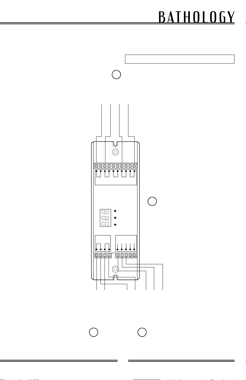
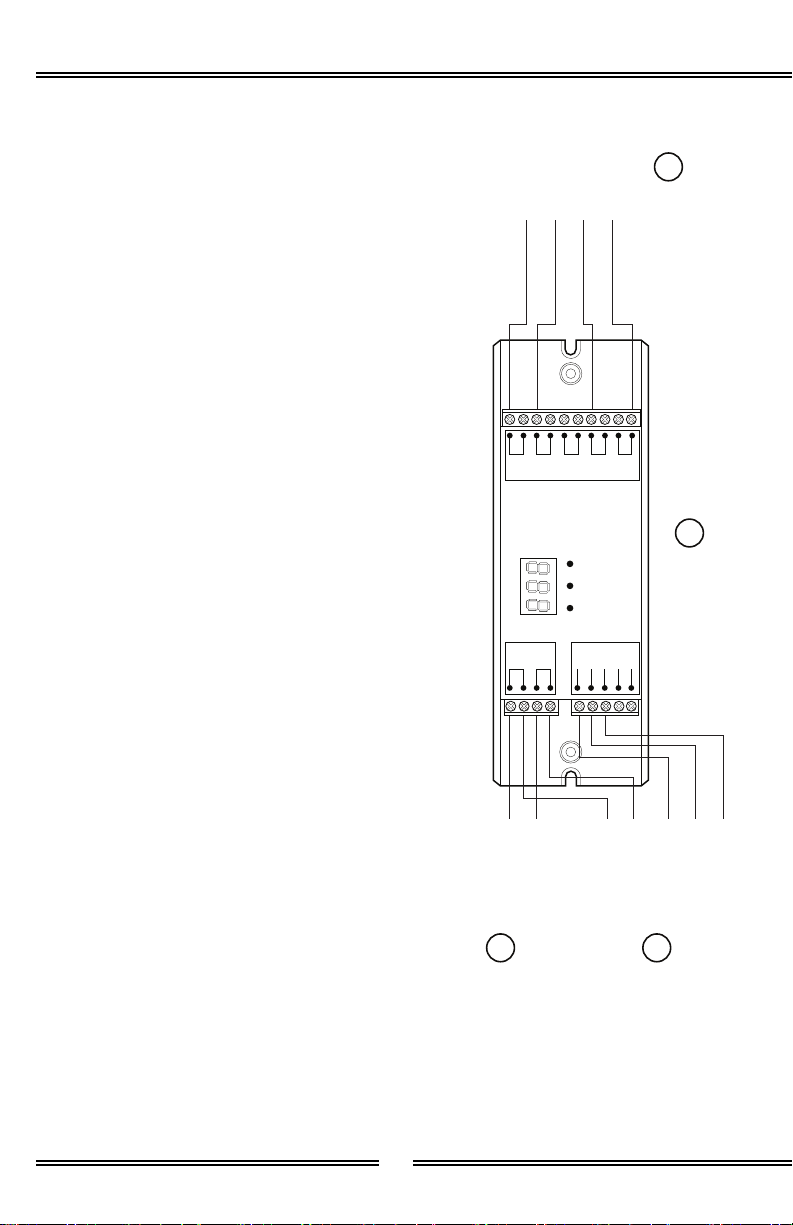
Installation - Himalayan Salt Panel (Interior (Phase 1))Installation - Himalayan Salt Panel (Interior (Phase 1))
1. Determine the desired locations
for the following: Power Supply
(G), DMX Decoder (F), Touch
Interface (J) and Salt Panel
Assembly (A). Note: DMX
Decoder (F) and Power Supply
(G) must be in an accessible, dry
location. Provided cord lengths
are 50’ maximum. DMX Decoder
and Power Supply should be
located next to each other.
Note: Himalayan Salt Panel
Assembly (A) can be recessed or
surface mounted.
2. Install electrical boxes for the
following: Touch Interface (J),
DMX Decoder (F), Power Supply
(G), and Salt Panel Assembly
(A).
3. Run a 120VAC externally
switched GFCI outlet to power
electrical box supplying power
to Power Supply (G).
4. Connect the following to the
DMX Decoder (F): Main Power
Cable from Power Supply (G),
Power Connector (I), DMX Cable
(H), and Light Extension Cable
(E). See wiring Diagram.
5. Route DMX Cable (H) and Power
Connector (I) to Touch Interface
(J) electrical box.
6. Wire DMX Cable (H) and Power
Connector (I) to Touch Interface
(J). See wiring Diagram.
7. Mount Touch Interface (J) to
Touch Interface Electrical box.
8. Route Light Extension Cable (E)
from DMX Decoder (F) to Salt
Panel Assembly (A).
9. Wire Light Extension Cable (E)
to DMX Decoder (F). See wiring
Diaram.
GND
V+ V+
R -
OUTPUT
DC INPUT
G -
B -
W -
V -
DMX+
DMX -
DMX+
DMX -
Power Supply Touch Interface
V+
V+
Black
Black Red
Red
Green
Blue
R G B
V+
GND
V - V -
DMX+
DMX - DMX Decoder
Light Extension
Cable
G
F
J
E

11
by
Installation - Himalayan Salt Panel (WIFI (Phase 1))Installation - Himalayan Salt Panel (WIFI (Phase 1))
1. Determine the desired locations
for the following: Power Supply
(G), WIFI Receiver (F), and Salt
Panel Assembly (A). Note: WIFI
Receiver (F) and Power Supply
(G) must be in an accessible,
dry location. Provided cord
lengths are 50’ maximum. Note:
Himalayan Salt Panel Assembly
(A) can be recessed or surface
mounted.
2. Install electrical boxes for the
following: Power Supply (G),
WIFI Receiver (F), and Salt
Panel Assembly (A).
3. Run a 120VAC externally
switched GFCI outlet to power
electrical box supplying power
to Power Supply (G).
4. Mount WIFI Bracket to wall and
place WIFI Receiver (F) into
Bracket.
5. Route Light Extension Cable (E)
from WIFI Receiver (F) to Salt
Panel Assembly (A).
6. Connect the Light Extension
Cable (E) to WIFI Receiver (F),
Red-Red, Green-Green, Blue-
Blue, Black-Black.
7. Connect the WIFI Receiver (F)
to the main power cable from
Power Supply (G).
V+
V+
R
R
G
G
B
B
WIFI Receiver
Light Extension
Cable
Wire Nut
F
E
12
Spectrum 620-C & 626-C
Installation - Himalayan Salt Panel (Remote (Phase 1))Installation - Himalayan Salt Panel (Remote (Phase 1))
1. Determine the desired locations
for the following: Power Supply
(G), RF Receiver (F), and Salt
Panel Assembly (A). Note: RF
Receiver (F) and Power Supply
(G) must be in an accessible,
dry location. Provided cord
lengths are 50’ maximum. Note:
Himalayan Salt Panel Assembly
(A) can be recessed or surface
mounted.
2. Install electrical boxes for the
following: RF Receiver (F),
Power Supply (G), and Salt
Panel Assembly (A).
3. Run a 120VAC externally
switched GFCI outlet to power
electrical box supplying power
to Power Supply (G).
4. Route Light Extension Cable
(E) from RF Receiver (F) to Salt
Panel Assembly (A).
5. Connect the Light Extension
Cable (E) to RF Receiver (F).
6. Connect the RF Receiver (F)
to the main power cable from
Power Supply (G).
RF Receiver
F
W
W4
+
-
OUTPU T
+
INPUT
12 -24VDC
+
+
+
+
+
+
B
G
R
V+
V+
V -
Light Extension
Cable
Power Supply
E
G

13
by
Page left intentionally blankPage left intentionally blank

14
Spectrum 620-C & 626-C
Installation - Himalayan Salt Panel (Phase 2)Installation - Himalayan Salt Panel (Phase 2)
1. From determined Salt Panel
Assembly (A) location, mark a
level line for height of Salt Panel
Assembly (A). (Helpful Tip: Use
a piece of 2x4, level and secure
to wall at determined height
temporarily to be used as a
ledger to support Salt Panel
Assembly (A))
2. The Salt Panel Assembly (A)
fixture may weigh up to 55
lbs. and require additional
framework or support. ¾”
Plywood is recommended to
help support the weight of the
fixture(s). See diagram on page
4.
3. Mount Salt Panel Assembly
(A) onto wall securing with
provided Mounting Screws (C)
into predrilled mounting holes.
4. After mounting Salt Panel
Assembly (A) slide in 4 Salt
Blocks (B) over Mounting Screw
(C) locations.
5. Connect Light Extension Cable
(E) to Salt Panel Assembly (A)
lead to complete assembly.
6. Repeat this process for each
additional Himalayan Salt Panel
Assembly, if any. A maximum
of 3 panel (each 48” x 12”)
or 7 panel (each 16” x 16”)
assemblies can be powered by a
single control.
7. Each Salt Panel Assembly (A)
has 2 connection points. Male
and female. Connect male from
one panel to female of another
for each additional panel.
8. Trim Boards (D) have been
supplied for either recessed or
surface installations.

15
by
Operation - InteriorOperation - Interior
Power Button:Power Button: Press and hold for two
seconds to turn the Touch Interface and
Salt Light Fixture on or off. Restores
most recent settings.
Touch Toggle:Touch Toggle: Press down on the wheel
at any point with your finger to select a
color, brightness, or pre-programmed
scene depending on which mode you
are in. Dragging your finger across the
wheel in each mode will result in the
following:
- In color mode, shift in color gradually.
- In brightness mode, shift in brightness
gradually.
- In pre-programmed scene mode, shift
in pre-programmed scene of colors.
Color and brightness are recalled when
the control is turned off and on.
Touch Toggle
Power Button
Brightness Mode
Color Mode
Color Mode
“1” Button
(Red / Scene 1)
“4” Button
(White / Scene 4)
“2” Button
(Green / Scene 2)
“3” Button
(Blue / Scene 3)
Pre-Programmed
Scene Mode
Color Mode :Color Mode : Press and hold for two
seconds to enable Color Mode.
- 1: Red
- 2: Green
- 3: Blue
- 4: White
Pre-Programmed Scene Mode:Pre-Programmed Scene Mode: Press
and hold for two seconds to enable
Pre-Programmed Scene Mode.
- 1: Red > Magenta > White >
Turquoise > Green > Yellow > White
> Magenta > Blue > Turquoise >
White > Yellow.
- 2: Red > Yellow > Green > Turquoise
> Blue > Magenta.
- 3: Yellow > Turquoise > Magenta.
- 4: Faster version of 1.
P B
C
S
1 2 3 4

16
Spectrum 620-C & 626-C
Installation - Himalayan Salt Panel (WIFI (Phase 3))Installation - Himalayan Salt Panel (WIFI (Phase 3))
1. In the IOS / Android app store
download the Smart Life Smart
Living app.
2. Once installed, you can either
create an account or tap “Try
Now” to continue without
creating an account. Note:
You will need to sign up for an
account to be able to use smart
home features such as Google
or Alexa.
3. Power on WIFI Receiver (F),
light should begin to flash on
and off rapidly.
4. In the app, select the Blue +
symbol in the upper right corner
to pair control.
5. Select the “Add Manually” tab at
the top, then select “Lighting”
tab.
6. Under lighting select “Light
Source (Wi-Fi)”. When
prompted, enter the WIFI
network that you will be using
to connect to.
7. Ensure light is flashing rapidly.
If not, follow on-screen steps
to reset control. Confirm light
is blinking then press “Next”.
Pairing process will not begin.
Note: If pairing is unsuccessful
the control may not be
picking up the WIFI signal. Try
repositioning the control.
8. Once pairing is successful, you
are all set to program your light.
17
by
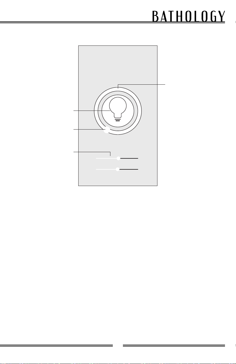
Operation - WIFIOperation - WIFI
Dark
Plain
Bright
Bright
Power Button
Cursor
Color Wheel
Brightness Slider
Power Button:Power Button: Turn on / turn off the
Salt Panel Assembly lights. Restores
most recent settings.
Color Wheel:Color Wheel: Press / drag to change
color.
Brightness Slider:Brightness Slider: Press / drag to
change light intensity.

18
Spectrum 620-C & 626-C
Installation - Himalayan Salt Panel (Remote (Phase 3))Installation - Himalayan Salt Panel (Remote (Phase 3))
1. Remote should already come
paired with receiver. Follow
steps below to repair existing
remote or new remote.
2. Pairing option 1 - on receiver
press the match key then
immediately pretty the On / Off
button on the remote.
Pairing option 2 - turn power
off then on to receiver then
immediately press the On / Off
button on the remote. Light
should blink 3 times indiciating
successful pairing.
19
by
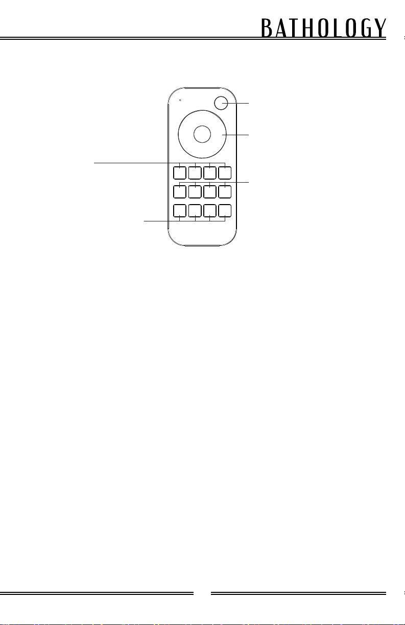
Operation - RemoteOperation - Remote
Power Button:Power Button: Turn on / turn off the
Salt Panel Assembly lights. Restores
most recent settings.
Color Wheel:Color Wheel: Press to change color.
Hold for continuous static color
adjustment.
Mode:Mode: Press to get 24 kinds of static
RGB color. Hold for continuous static
color adjustment.
Blend:Blend: Press to run next dynamic
mode. Hold to run mode-cycle.
Fast Forward:Fast Forward:
For dynamic RGB mode: Adjusts speed.
Press for 10 levels of inceased speed.
Hold for 2 seconds to set default speed.
For static RGB color: Adjusts saturation.
Press for 11 levels of increased mixture
of white to current static RGB color.
Hold for 1 to 6 seconds for continuous
256 levels adjustement.
Brightness:Brightness: Press to turn off lights after
30 seconds. Hold for 2 seconds to turn
off lights after 60 seconds.
R, G, and B:R, G, and B: Press to get Red, Green,
and Blue respectively. Press and hold
for 1 to 6 seconds to adjust R/G/B
brightness continously to achieve
millions of colors.
W:W: Press to get White (RGB mix). Press
and hold for 1 to 6 seconds to adjust
saturation continously, increasing
mixture of white to current RGB color.
Scene Recall 1 - 4:Scene Recall 1 - 4: Press to recall scene
1, 2, 3, or 4 respectively. Hold for 2
seconds to save current brightness into
respective scene (ex: S1 saves to S1).
The LED indicator displays green to
confirm save.
Power Button
Color Wheel
R, G, B, W
Cycle
Mode
Fast Forward
Brightness
Scene Recall 1-4

20
Spectrum 620-C & 626-C
Replacement PartsReplacement Parts
Contact your Bathology
representative for Spectrum
620-C / 626-C Color Light Salt Panel
replacement parts.
800-957-2862
www.Bathology.com
Specifications - Salt PanelSpecifications - Salt Panel
AssemblyAssembly
Specifications - InteriorSpecifications - Interior
ControlControl
Salt BlockSalt Block
Composition:Composition: Himalayan Salt
Dimensions:Dimensions: 3-7/8” x 7-7/8”
Himalayan Salt PanelHimalayan Salt Panel
Dimensions (620-C):Dimensions (620-C): 11-5/8”H x
47-1/4”W x 2-5/8”D
Dimensions (626-C):Dimensions (626-C): 15-1/2”H x
15-3/4”W x 2-5/8”D
Composition:Composition: Maple Plywood,
Aluminum
Mounting ScrewsMounting Screws
Size:Size: #10 x 2-1/2”
LED LightLED Light
Operating Voltage:Operating Voltage: 24VDC
Power Consumption:Power Consumption: 33 Watts per
panel
Lumens:Lumens: 924 per Panel
DMX DecoderDMX Decoder
Operating Voltage:Operating Voltage: 24VDC
Power Consumption:Power Consumption: 192 Watts
Amperage:Amperage: 4 Channels, 8 Amps
Dimensions:Dimensions: 2.3” x 6.7” x 1.5”
Power SupplyPower Supply
Operating Voltage:Operating Voltage: 120VAC
Output Voltage:Output Voltage: 24VDC
Power Composition:Power Composition: 120W
Nominal Amperage:Nominal Amperage: 5A / 120V
Dimensions:Dimensions: 2”W x 7”D x 1-1/4”H
Power Cable:Power Cable: 2-Wire, #18 AWG,
6” Long
Touch InterfaceTouch Interface
Operating Voltage:Operating Voltage: 24VDC
Housing:Housing: Aluminum Housing Glass
Panel
Load:Load: 2A per Channel, 6A Total
Dimensions:Dimensions: 3-3/16”W x 4-7/8”H x
11/16”D
This manual suits for next models
1
Table of contents
Other Bathology Lighting Equipment manuals

Bathology
Bathology Spectrum 510 User manual

Bathology
Bathology Spectrum 441 User manual

Bathology
Bathology Spectrum 350 User manual

Bathology
Bathology Spectrum 321 User manual

Bathology
Bathology Spectrum 440 User manual

Bathology
Bathology Spectrum 620-W User manual

Bathology
Bathology Spectrum 441D User manual
Popular Lighting Equipment manuals by other brands

RSA Lighting
RSA Lighting COMBOLIGHT LV850MH Specification sheet

LightProcessor
LightProcessor DMuX Installation and operating manual

Panlux
Panlux LEDMED LM06000005 manual

BECS
BECS BECSys2 Operator's manual

Honeywell
Honeywell Ex-Or MS1500PF Installation and commissioning instructions

ccei
ccei PF10R511 Technical instructions


