Bathology Spectrum 510 User manual
BATHOLOGY
Spectrum 510
Color Bathing Experience
Installation and Operation Manual
rediscover bathing

2
Spectrum 510
ContentsContents
Installation ConsiderationsInstallation Considerations ---------------------------------------------
Installation - OverivewInstallation - Overivew --------------------------------------------------
Installation - DMX Driver / Power SupplyInstallation - DMX Driver / Power Supply ----------------------------
Installation - Touch InterfaceInstallation - Touch Interface ------------------------------------------
Installation - Brilliance Light FixtureInstallation - Brilliance Light Fixture -----------------------------------
OperationOperation ----------------------------------------------------------------
Product CareProduct Care -------------------------------------------------------------
Replacement PartsReplacement Parts -------------------------------------------------------
SpecificationsSpecifications ------------------------------------------------------------
TroubleshootingTroubleshooting ---------------------------------------------------------
NotesNotes ---------------------------------------------------------------------
33
44
55
77
1010
1414
1616
1616
1616
1818
2121
3
BATHOLOGY
by
Carefully review all
installation options and instructions
before proceeding.
For safety purposes, use
safety goggles at all times.
Before wiring to power
supply, turn off electricity at the fuse or
circuit breaker box.
Check for piping /
electrical before cutting or drilling.
Some electrical
components are not waterproof.
If there is any risk of
uninsulated electrical connections in
your wall / ceiling area, use insulating
gloves.
All wiring must be done in
accordance with National Electric Code
and local building code.
Prior to installation,
consider the placement carefully, taking
into account the location of electrical,
plumbing, and other fixtures.
Touch Interface can be
installed outside of a wet environment,
on a vertical wall, convenient for user
operation. It can be installed a dry
bathing environment 48” above the
floor maximum. It must also avoid
elements such as direct water and
steam emissions.
Installation ConsiderationsInstallation Considerations
Please read this manual in its entirely prior to installationPlease read this manual in its entirely prior to installation
! IMPORTANT
! IMPORTANT
! IMPORTANT
12
4
Spectrum 510
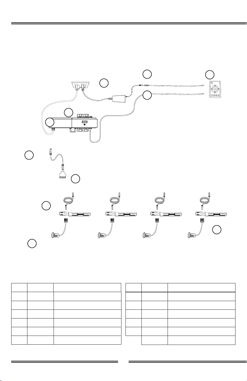
Installation - OverviewInstallation - Overview
Package Includes
Item Quantity Description
A 1 DMX Driver
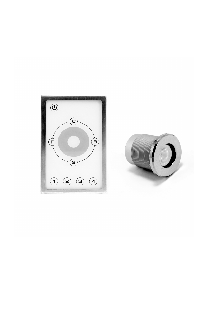
B 1 Touch Interface
C 1 Power Supply, 12VDC
D 1 Power Supply Connector, 50’
E 1 DMX IN Cable, 50’
F 1 Cat6 Cable, 1’
Item Quantity Description
G 1 RJ-45 Splitter
H 1 Cat6 Cable, 25’
I 1 Brilliance 410 Light Fixture
J 1 16” Location Templates
K 1 DMX Power Supply, 48VDC
1Silicone Sealant, 1 oz tube
DMX Driver
Accessible, Dry Location Desired Interface
Location
Desired Light Locations
Touch Interface
16” Location
Templates
Cat6 Cable, 1’
RJ-45
Splitter
Cat6 Cable,
25’
Power Supply,
12VDC
Ground 120VAC, 15
Amp Duplex Outlet
NOTE: Do not install Touch Interface
inside wet environment.
NOTE: Both ends of splitter must be
used, if a splitter is used. Lights are in
series and will not illuminate if a Splitter
port is left open. Exclude Splitter and
Cat6 Cable, 1’ if only one light will be
used in a particular zone / port.
Power Supply
Connector, 50’
DMX IN
Cable, 50’
Brilliance 410
Light Fixture
A
B
J
F
G
H
C
D
E
I
DMX Power
Supply, 48VDC K
NOTE: It is recommended that all electrical
equipment be tested prior to installation.
NOTE: Do not hot swap any electrical
components. Fully disconnect system from
power source before swapping electrical
components.

1 2
1 2
5
BATHOLOGY
by
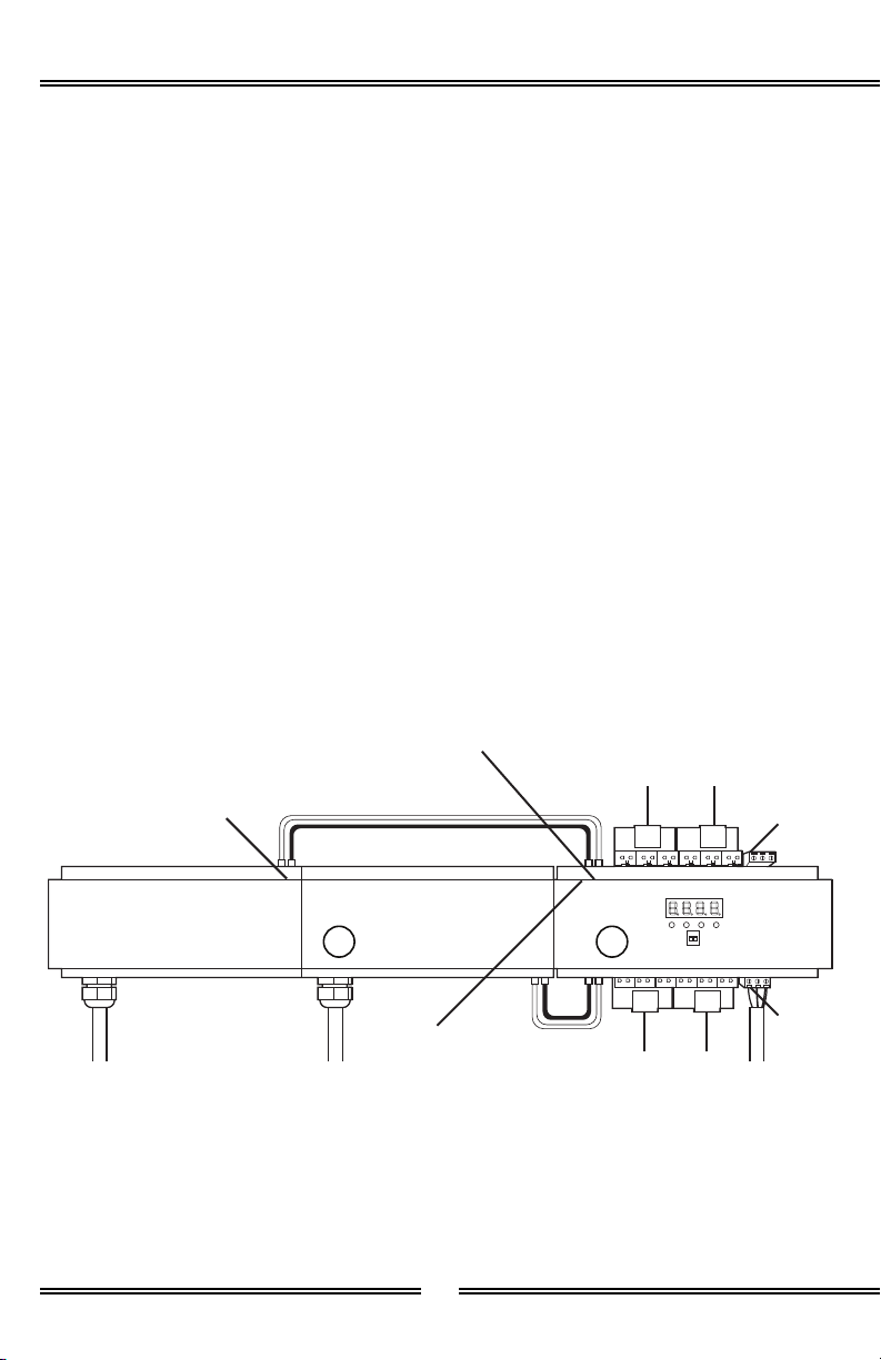
DMX Driver
DMX Power
Supply
Port 2
Port 3
48VDC
DMX Out
48VDC
DMX In
DMX First Power
Supply Input
DMX Second Power
Supply Input
120VAC Power In
Port 1
Port 4
DMX IN
DMX IN
AK
Installation for 1-24 Lights Dip Switches
Installation - DMX Driver / Power SupplyInstallation - DMX Driver / Power Supply
Brilliance lights run on 350mA. Ensure
that Dip switch 1 and 2 are both in the
down position at 350mA.
1 12 2
200mA
250mA
300mA
350mA
1. Determine best location for
DMX Driver (A) and DMX Power
Supply (K), making note of cord
lengths.
2. Using a screwdriver fully loosen
the 48VDC Output + and – on
power supply (K) and 48VDC
Input + and – on the DMX driver
(A).
3. Connect the Red wire to the +
Output on the power supply (K)
and the other end to the + Input
on the DMX driver (A).
4. Connect the Black wire to the -
Output on the power supply (K)
and the other end to the - Input
on the DMX driver (A).
1 2
6
Spectrum 510
Additional Power Supply for 25 - 48 Lights
Installation - DMX Driver / Power Supply (Continued)Installation - DMX Driver / Power Supply (Continued)
DMX Driver
DMX Power
Supply
Port 2
Port 3
48VDC
DMX Out
48VDC
DMX In
DMX Second Power
Supply Input
120VAC Power In
Port 1
Port 4
DMX IN
DMX IN
AK
1. Follow and complete installation
for 1-24 lights.
2. Mount power supply (K) next to
first power supply (K).
3. Using a screwdriver fully loosen
the 48VDC Output + and – on
power supply (K) and 48VDC
Input + and – on the DMX driver
(A).
4. Connect the Red wire to the +
Output on the power supply (K)
and the other end to the + Input
on the DMX driver (A).
5. Connect the Black wire to the -
Output (K) on the power supply
and the other end to the - Input
on the DMX driver (A).

7
BATHOLOGY
by
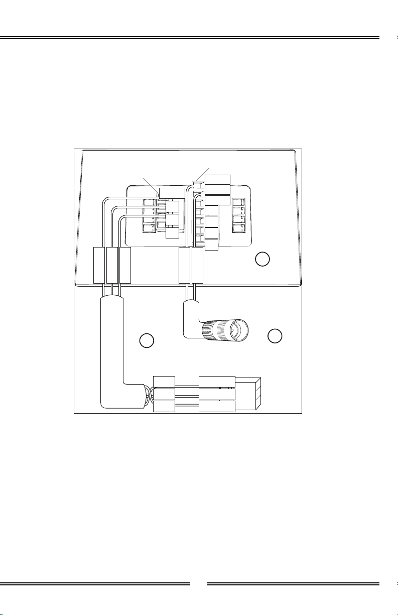
Touch Interface
Screwdriver
Loosen
Orange 4 Screw
Terminal Block
6 Screw
Terminal Block
Silicone after
wiring
Tape
B
Installation - Touch InterfaceInstallation - Touch Interface
1. Determine the desierd location
for the Touch Interface (B),
making note of the cord lenghts.
2. Cut a 1-1/2”W x 2-13/32” H
hole in desired location for the
Touch Interface (B).
3. Install a standard single gang
electrical box in an accessible
dry location.
4. Run a grounded 120VAC
from the power supply to
the accessible dry location’s
electrical box.
5. Run the DMX IN Cable (E) wires
and the Power Supply Connector
(D) wires to the Touch Interface’s
(B) hole cutout.
6. Remove orange 4 screw terminal
block and 7 screw terminal block
from respective pin terminals.
7. Using a screwdriver, fully loosen
the “GND”, “D-”, and “D+”
sections of the orange 4 screw
terminal, and “GND”, and “V in
+” of the 7 screw terminal.
8. Connect the DMX IN Cable (E)
GND to the “GND” orange 4
screw terminal block.
9. Connect the DMX IN Cable (E)
Red D- to the “D-” orange 4
screw terminal block.
10. Connect the DMX IN Cable (E)
Black + to the “D+” orange 4
screw terminal block.

8
Spectrum 510
11. Connect the Power Supply
Connector (D) White - to the
“GND” 7 screw terminal block.
12. Connect the Power Supply
Connector (D) Black + to the “V
in +” 7 screw terminal block.
13. Using a screw driver, tighten
the “GND”, “DMX -”, “DMX +”,
sections of the 4 screw terminal,
and “GND”, and “V in +” of the
7 screw terminal.
14. Insert orange 4 screw terminal
block and 7 screw terminal
block into their respective pin
terminals.
15. Remove DMX Driver’s (A) DMX
IN screw terminal block from pin
terminal.
16. Connect the DMX IN Cable (E)
Ground to the DMX Driver’s (A)
DMX IN screw terminal block’s
“GND”.
17. Connect the DMX IN Cable (E)
Red to the DMX Driver’s (A) DMX
IN screw terminal block’s “D-”.
18. Connect the DMX IN Cable (E)
Black to the DMX Driver’s (A)
DMX IN screw terminal block’s
“D+”.
19. Using a screwdriver, tighten the
“GND”, “D-”, and “D+” sections
of the DMX IN screw terminal
block.
20. Insert DMX IN screw terminal
block into its pin terminal.
Installation - Touch Interface (Continued)Installation - Touch Interface (Continued)
21. Test light system prior to
mounting Touch Interface (B)
to wall. Verify connections are
secure and working properly.
22. Apply a 1/8” bead of silicone
around the back of the Touch
Interface (B).
23. Peel off tape and mount Touch
Interface (B) to hole cutout area.
24. Apply a 1/8” of silicone around
the edge of the mounted Touch
Interface (B) as required to form
a water tight seal.
25. Allow silicone to cure for 24
hours before exposing product
to any source of moisture.
9
BATHOLOGY
by
Installation - Touch Interface (Continued)Installation - Touch Interface (Continued)
Touch Interface
DMX Out
Screw Terminal (Orange)
Power In
Screw Terminal
GND V+
V in +
GND
D+ R
D+ G
B
D- W
Black D+
Black +
Black D+D+
GroundGND
Red D-
White -
Red D-D-
Power Supply
Connector, 50’
DMX IN
Cable, 50’
B
D
E
Ground

10
Spectrum 510
Installation - Brilliance Light FixturesInstallation - Brilliance Light Fixtures
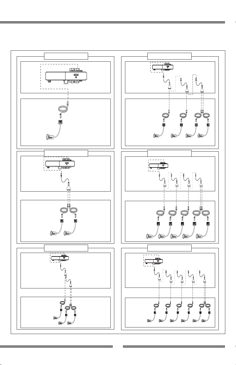
1. Determine number of lights per
port. Limit 12 lights per port.
2. Construct light assembly using
the diagrams on the next page.
3. Repeat steps 1 and 2 for
additional zones.
4. Determine desired Brilliance
Light Fixture (I) location.
Warning:Warning: The Splitters (G) should be
kept in an accessible location when
installed. Only use the Splitters (G)
when assembling the Brilliance Light
Fixtures (I) and ocmponents of this kit.
Important:Important: Driver has 4 ports. Each
port operates 1212 lights max. Take this
into consideration when planning light
installation.
RJ-45
Splitter
IN
OUT
IN Supports:
- Cable, 1’ (F)
(Comes from DMX Driver)
OUT Supports:
- Cable, 1’ (F)
- Cable, 25’ (H)
(Goes toward Lights)
G
12
12
12
12
12
12
11
BATHOLOGY
by
1 Light Example
Dry
Accessible
Location
Dry
Accessible
Location
Dry
Accessible
Location
Dry
Accessible
Location
Dry
Accessible
Location
Dry
Accessible
Location
Desired Light
Location
Desired Light
Location
Desired Light
Location
Desired Light
Location
Desired Light
Location
Desired Light
Location
2 Light Example
3 Light Example
4 Light Example
5 Light Example
6 Light Example

12
Spectrum 510
Desired Fixture
Location
Notch used to align
xture center to other
xture centers
16” Location
Templates
16” Location
Templates
1” Ceiling /
Wall Material
J
J
Installation - Brilliance Light Fixtures (Continued)Installation - Brilliance Light Fixtures (Continued)
1/8” Silicone Bead
Placement
(Wet Environment)
Brilliance 410
Light Fixture
I
5. FOR REMODELS: Skip to 6.
FOR NEW ROOMS: Mount
16” Location Template (J) to
ceiling joist to indicate desired
Brilliance Light Fixture (I)
location. Use notches to quickly
align desired location to other
fixtures in the room.
6. Make a 1-5/8” hole in desired
location.
7. Install light assemblies.
8. Apply a 1/8” bead of silicone
around the edge of the Brilliance
Light Fixture (I) as required to
form a water tight seal.
9. Mount Brillinace Light Fixture (I)
to ceiling through 1-5/8” cutout.
10. Repeat steps 4 - 9 for each light.
11. Allow silicone to cure for 24
hours before exposing product
to any source of moisture.

13
BATHOLOGY
by
Page left intentionally blankPage left intentionally blank

14
Spectrum 510
OperationOperation
On / OffOn / Off
Power Off -
Power On -
ColorColor
“C” Button -
“1” Button -
“2” Button -
“3” Button -
“4” Button -
Touch Toggle
-
BrightnessBrightness
“B” Button -
“1”, “2”, “3”,
“4” Button -
Touch Toggle
-
Press and hold for 2 seconds. Turns on Touch Interface. Restores most
recent settings.
Press and hold for 2 seconds. Turns off touch Interface.
Press and Hold for 2 seconds. Enables color mode.
Red.
Green.
Blue.
White.
Press and drag in a clockwise or counter-clockwise motion to cycle
through all colors.
Press and hold for 2 seconds. Enables brightness mode.
Uses color mode or pre-programmed scene mode “1”, “2”, “3”,
“4” functionality, based on which mode was used prior to brightness
mode.
Press and drag in a clockwise motion to increase brightness. Counter-
clockwise decreases brightness.

15
BATHOLOGY
by
Power Light Touch Toggle
(Grey Section)
“P” Button
(Pre-Programmed
Scenes)
“C” Button
(Color)
“B” Button
(Brightness)
“1” Button
(Red /
Scene 1)
“2” Button
(Green /
Scene 2)
“3” Button
(Blue /
Scene 3)
“4” Button
(White /
Scene 4)
Operation (Continued)Operation (Continued)
Pre-Pre-
ProgrammedProgrammed
SceneScene
“P” Button -
“1” Button -
“2” Button -
“3” Button -
“4” Button -
Touch Toggle
-
Press and hold for 2 seconds. Enables Pre-Programmed Scene mode.
Red - Magenta - White - Turquoise - Green - Yellow - White - Magenta
- Blue - Turquoise - White - Yellow.
Red - Yellow - Green - Turquoise - Blue - Magenta
Yellow - Turquoise - Magenta
Red - Magenta - White - Turquoise - Green - Yellow - White - Magenta
- Blue - Turquoise - White - Yellow (Faster version of “1”)
Press and drag in a clockwise or counter-clockwise motion to cycle
through 10 pre-programmed scenes.

16
Spectrum 510
Replacement PartsReplacement Parts
Contact your Bathology representative
for Spectrum 510 Color Bathing
Experience replacement parts.
800-957-2862
www.Bathology.com
Product CareProduct Care
For routine cleaning, simply use
a soft damp cloth and common
household soap. Use a damp cloth
to wipe clean, then dry. Clean
product frequently to avoid calcium
deposits on surfaces. Use only
mild soap. Never use abrasiveNever use abrasive
cleaners, bleach, disinfectantscleaners, bleach, disinfectants
or cleaning products containingor cleaning products containing
alcohol, ammonia, hydrochloricalcohol, ammonia, hydrochloric
or phosphoric acidsor phosphoric acids as they may
damage the product’s finish. To
clean electrical components, gently
wipe down using a dry cloth or
duster. Never use a wet duster,Never use a wet duster,
water, or any other liquid to cleanwater, or any other liquid to clean
the device.the device.
SpecificationsSpecifications
DMX DriverDMX Driver
Operating Voltage:Operating Voltage: 48VDC
Power Consumption:Power Consumption: 192W
Nominal Amperage:Nominal Amperage: .35 x 12 Amps
Power Output:Power Output: 4-47VDC, 1050mA /
Port (3x350mA)
Dimensions:Dimensions: 5.47”L x 2.87”H x
2.60”D
DNX IN Cable:DNX IN Cable: 3-Pin, 24Gauge, 50’
Listing:Listing: UL / CE / RoHS
Power Supply DMX DriverPower Supply DMX Driver
Operating Voltage:Operating Voltage: 120VAC
Output voltage:Output voltage: 48VDC
Power Consumption:Power Consumption: 96W
Nominal Amperage:Nominal Amperage: 2 Amps
Dimensions:Dimensions: 5.47”W x 2.87”H x
2.60”D
Listing:Listing: UL / CE / RoHS
Touch InterfaceTouch Interface
Trim:Trim: Steel, Polished Chrome Finish
Housing:Housing: Aluminum Housing, Glass
Panel
Dimensions:Dimensions: 3-3/16”W x 4-15/16”H
x 11/16”D
Loading:Loading: 2A per Channel, 6A in
Total

17
BATHOLOGY
by
Specifications (Continued)Specifications (Continued)
Power Supply Touch PadPower Supply Touch Pad
Operating Voltage:Operating Voltage: 120VAC
Output voltage:Output voltage: 12VDC
Power Consumption:Power Consumption: 48W
Nominal Amperage:Nominal Amperage: 1.8 Amps
Dimensions:Dimensions: 2”W x 7”L x 1-1/4”H
Connector:Connector: 12V - 50’ Long
Brilliance FixtureBrilliance Fixture
Type:Type: LED RGB
Operating Voltage:Operating Voltage: 12VDC
Maximum Input Current:Maximum Input Current: 350mA
LED:LED: 1 x 3 Watt RGB in One
Beam Angle:Beam Angle: 40°
Lumen:Lumen: 88
Trim Finish:Trim Finish: Polished Chrome
Housing Composition:Housing Composition: First Grade
Stainless Steel
Lens:Lens: Clear or Frosted, 7/8”
Diameter
Lens Composition:Lens Composition: Otpical Grade
PMMA
Rough-in Cutout:Rough-in Cutout: 1-5/8”
Rating:Rating: IP68
Certifications:Certifications: CE / RoHS / WEEE
Max Operating Temperature:Max Operating Temperature: 130°F
when installed per instructions
Construction TemplateConstruction Template
Composition:Composition: Steel, Galvanized,
Gauge 22
Dimensions:Dimensions: 15-1/8” L x 1/32” H x
3” D

18
Spectrum 510
TroubleshootingTroubleshooting
1. Press the Up button until A.001
displays. Press enter then Up or
Down to change if not showing
A.001 then press back to save. If
already showing A.001 proceed
to step 2
2. Press the Up button, CH12
should display.
3. Press the Up button, PF01
should display.
4. Press the Up button, BT16
should display.
5. Press the Up button, 9A1.0
should display.
6. Press the Up button, DP1.1
should display.
7. Press the Up button, Run1
should display.
1. Press Down on the DMX driver
until RUN1 displays then press
Enter
2. Press up until RUN2 displays
then press Back button.
3. Power Cycle DMX driver for at
least 10 seconds. If you have 2
power supplies both will have to
be unplugged at the same time.
4. Display should now read RUN2.
The DMX driver will turn on
automatically when supplied with
power. The screen is always on. The
screen will default back to A.001 after
15 of inactivity.
Warning:Warning: Do not change out lights with
DMX driver power on.
Default SettingsDefault Settings
Press enter then Up or Down to
change if not showing default setting
listed below then press back to save.
If already showing default proceed to
next step.
Enter Testing ModeEnter Testing Mode

19
BATHOLOGY
by
1. Press UP button until 01.00
displays then press Enter
2. Press Down until 01.FL displays.
3. Go to room and verify Red is
working on all Zone 1 lights
4. Press Up then Enter then Up until
01.00 displays then press Back
1. Press UP button until 04.00
displays then press Enter
2. Press Down until 04.FL displays.
3. Go to room and verify Red is
working on all Zone 2 lights
4. Press Up then Enter then Up until
04.00 displays then press Back
1. Press UP button until 03.00
displays then press Enter
2. Press Down until 03.FL displays.
3. Go to room and verify Blue is
working on all Zone 1 lights
4. Press Up then Enter then Up until
03.00 displays then press Back
1. Press UP button until 06.00
displays then press Enter
2. Press Down until 06.FL displays.
3. Go to room and verify Blue is
working on all Zone 2 lights
4. Press Up then Enter then Up until
06.00 displays then press Back
1. Press UP button until 02.00
displays then press Enter
2. Press Down until 02.FL displays.
3. Go to room and verify Green is
working on all Zone 1 lights
4. Press Up then Enter then Up until
02.00 displays then press Back
1. Press UP button until 05.00
displays then press Enter
2. Press Down until 05.FL displays.
3. Go to room and verify Green is
working on all Zone 2 lights
4. Press Up then Enter then Up until
05.00 displays then press Back
Zone 1Zone 1
Red Zone 1 Channel 1Red Zone 1 Channel 1
Zone 2Zone 2
Red Zone 2 Channel 4Red Zone 2 Channel 4
Blue Zone 1 Channel 3Blue Zone 1 Channel 3 Blue Zone 2 Channel 6Blue Zone 2 Channel 6
Green Zone 1 Channel 2Green Zone 1 Channel 2 Green Zone 2 Channel 5Green Zone 2 Channel 5

20
Spectrum 510
1. Press UP button until 10.00
displays then press Enter.
2. Press Down until 10.FL displays.
3. Go to room and verify Red is
working on all Zone 4 lights.
4. Press Up then Enter then Up until
10.00 displays then press Back.
1. Press UP button until 09.00
displays then press Enter.
2. Press Down until 09.FL displays.
3. Go to room and verify Blue is
working on all Zone 3 lights.
4. Press Up then Enter then Up until
09.00 displays then press Back.
1. Press UP button until 12.00
displays then press Enter.
2. Press Down until 12.FL displays.
3. Go to room and verify Blue is
working on all Zone 4 lights.
4. Press Up then Enter then Up until
12.00 displays then press Back.
1. Press UP button until 11.00
displays then press Enter.
2. Press Down until 11.FL displays.
3. Go to room and verify Green is
working on all Zone 4 lights.
4. Press Up then Enter then Up until
11.00 displays then press Back.
Zone 4Zone 4
Red Zone 4 Channel 10Red Zone 4 Channel 10
Blue Zone 3 Channel 9Blue Zone 3 Channel 9 Blue Zone 4 Channel 12Blue Zone 4 Channel 12
Green Zone 4 Channel 11Green Zone 4 Channel 11
1. Press UP button until 07.00
displays then press Enter
2. Press Down until 07.FL displays.
3. Go to room and verify Red is
working on all Zone 3 lights
4. Press Up then Enter then Up until
07.00 displays then press Back
1. Press UP button until 08.00
displays then press Enter
2. Press Down until 08.FL displays.
3. Go to room and verify Green is
working on all Zone 3 lights
4. Press Up then Enter then Up until
08.00 displays then press Back
Zone 3Zone 3
Red Zone 3 Channel 7Red Zone 3 Channel 7
Green Zone 3 Channel 8Green Zone 3 Channel 8
Troubleshooting (Continued)Troubleshooting (Continued)
Table of contents
Other Bathology Lighting Equipment manuals

Bathology
Bathology Spectrum 441 User manual

Bathology
Bathology Spectrum 441D User manual

Bathology
Bathology Spectrum 620-C User manual

Bathology
Bathology Spectrum 620-W User manual

Bathology
Bathology Spectrum 321 User manual

Bathology
Bathology Spectrum 350 User manual

Bathology
Bathology Spectrum 440 User manual
Popular Lighting Equipment manuals by other brands

GigaTera
GigaTera EFL Series user guide

Barthelme
Barthelme AQUALUC C:URVE mini Instructions for installation and operation

Arlec
Arlec ABL104 installation instructions

Life
Life 39.9TS042620N40 user manual

Lightolier
Lightolier Calculite C7E170HW specification

Loevschall
Loevschall F15-350 Instructions for use


