manuals.online logo
Brands
  1. Home
  2. •
  3. Brands
  4. •
  5. Bathology
  6. •
  7. Lighting Equipment
  8. •
  9. Bathology Spectrum 321 User manual

Bathology Spectrum 321 User manual

Spectrum 321
Steam Room / Shower LED Light
Installation and Operating Manual
BATHOLOGYby
Spectrum 321
Installation Notes
Environmentally Friendly, Energy Efficient
Consider the use of lighting within the bathing
environment when determining the Spectrum
321 installation location.
Specifications
Fixture Type: Recessed Ceiling Downlight, LED
Dimming: With most incandescent, magnetic low
voltage, and electronic low voltage wall
box dimmers
Insulation Contact: IC Rated
Minimum Installation Height: 5-1/4”
Maximum Ceiling Thickness: 1-1/2"
Rough-in Cut-Out: 4-3/8”
Housing 4”Recessed: Aluminum, sealed for Air-Loc
compliance
Housing Length: 12-1/2”
Housing Width: 4-3/4”
Housing Height: 4-3/8”
Testing: U.L. Listed, Suitable for Wet Locations
Labels: Union made
Trim: Metal, Electrostatic Powder Paint
Trim Profile: 1/8”
Trim Diameter: 5”
Lens: Etched Frosted Tempered Glass with Clear
Center
LED Driver: 120VAC at 50 / 60Hz
LED Driver Input Power: 11.7W (+/-5%)
LED Driver Input Currant: Max 0.10A
Starting Temperature: Minimum -25°C
LED Life: 50,000 hours
Color Temperature: 4100k
Color Rendering Index: 90 CRI minimum
Optical System: Computer-optimized reflector
Lumens: 600
Installation
Package Includes
2
1.
Warning: For your safety read and understand
instructions completely before starting. Before
wiring to power supply, turn off electricity at the
fuse or circuit breaker box.
Note: Spectrum 321 is a recessed fixture designed
to meet the latest NEC requirements and are listed
in full compliance with the relevant UL standard(s).
Before attempting installation of any recessed
lighting fixture, check your local electrical building
code. This code sets the wiring standards and
installation requirements for your locality and
should be understood before starting work.
Note: Spectrum 321 is designed for direct contact
with insulating materials that are approved for this
application. The Spectrum 321 may also be used
in non-insulated ceilings.
Note: Compatible ceiling thickness: 1/2“ to 1-1/2”
-
-
-
-
No harmful ultraviolet or infrared wavelengths.
No lead or mercury, RoHS compliant.
Comparable light output to 65W incandescent
Shallow housing allows for fit in 2”x 6”
construction.
-
-
-
-
- (1) Housing 4” Recessed, Aluminum, sealed for
Air-Loc
- (1) LED optical reflector
- (1) Trim, Metal with frosted glass lens, 5” diameter,
1/8” profile
- (3) Retention clip tape strip
- (1) Silicone sealant, 1 ounce tube
- (1) 16” Mounting template
- (1) Installation template
- Installation and operating manual
Important: It is recommended that all electrical
equipment be tested prior to installation.
Important: The purple and grey wires MUST be
used to dim the light fixture.
BATHOLOGYby
Spectrum 321
For Remodels: Skip to step 3.
For New Rooms: Mount 16” mounting template
to ceiling joist to indicate desired Spectrum 321
location. Use notches to quickly align desired
location to other fixtures or elements in the
room (see figure 1).
Provide electrical service according to your
electric code to the selected fixture installation
area. Supply wire insulation must be rated for
at least 194°F (90°C). Note: This fixture
requires a flexible electrical supply.
Cut the required cut-out within the ceiling
backer-board. Note: An installation template is
provided for installations that do not require the
16” mounting template.
Apply ceiling waterproof material (tile, stone,
etc.) around the fixture housing cut-out. Note:
Finished hole diameter must not exceed 4-3/8”
diameter. Ceiling materials must not exceed
1-1/2” thick.
Remove junction box cover. Remove the
appropriate knock-outs to accomodate the type
of electrical supply being used (see figure 2).
Remove fixture wire box cover and appropriate
knock-out to connect flexible metal conduit to
wiring box with proper connector (not supplied).
Connect supply wires to fixture wires with proper
size wire nuts (not supplied), so as to cover all
bare current-carrying conductors. Connect
black fixture wire to black (hot) power supply
wire, white fixture wire to white (neutral) power
supply wire, green fixture wire to green (ground)
wire. Note: The purple and grey wires must be
used to dim the light fixture.
Place all wiring and connections back into
wiring box and replace cover.
Installation (Continued)
3
2.
3.
4.
5.
6.
7.
8.
9.
Press housing through ceiling opening so it is
flush to the finish material (see figure 3).
While holding fixture firmly in place, push
retention clips outward until each clip tab clicks
into position. Note: To remove housing from
ceiling, push tab on clip upward to disengage.
10.
11.
Retention
Clips
Figure 3
Joist
Joist
Notch used to align
fixture center to other
fixture centers
Desired Fixture
Location
Figure 2
Figure 1
Knock-Out
LED Driver
Quick
Connector
BATHOLOGYby
Spectrum 321
Installation (Continued)
4
Replacement Parts
Contact your Bathology representative for Spectrum 321
LED Steam Room/In-Shower Light replacement parts.
Description
Housing
Trim, satin nickel
Trim, white
Optic Assembly
Part Number
Spectrum053
Spectrum054
Spectrum055
Spectrum074
900-0122-1113-1
BATHOLOGY
rediscover bathing
A division of Bathing Brands, Inc.
www.Bathology.com 800-957-2862
Product Care
For routine cleaning simply use a soft damp cloth
and common household soap. Use the damp cloth
to wipe clean, then dry. Clean product frequently to
avoid calcium deposits on surfaces. Use only mild
soap based detergents. Never use abrasive
cleaners, bleach, disinfectants or cleaning products
containing alcohol, ammonia, hydrochloric or
phosphoric acids as they will damage the product’s
finish.
To seal housing after confirming correct operation,
apply supplied tape strips to completely cover each
of the three retention clips and slots. Do not
substitute with other materials (see figure 4).
Remove LED shield from housing.
Assemble optic assembly (see figure 5).
Insert optic assembly into housing, with mounting
feet aligned with raised screws. Twist optic assembly
clockwise so mounting feet engage screws. Twist
firmly to lock in place (see figure 6).
Locate Spectrum 321 trim and lay a thin 1/8” bead
of RTV silicone (provided) around the trim perimeter.
Note: Install trim with clean hands or cloth to
prevent staining.
With silicone applied, insert trim into fixture by lining
up trim springs with the housing opening and
pressing trim up towards the ceiling. Note: Avoid
contact with optic housing when pushing in trim.
Allow silicone to cure for 24 hours before exposing
product to any source of moisture.
12.
13.
14.
15.
16.
17.
18.
Figure 5
Optic
Assembly
Mounting Foot
Raised Screw
Raised Screw
Twist to Lock
into Place
Figure 6
Figure 4
Tape Strips to
Cover Retention
Clips (3 Places)

Other Bathology Lighting Equipment manuals

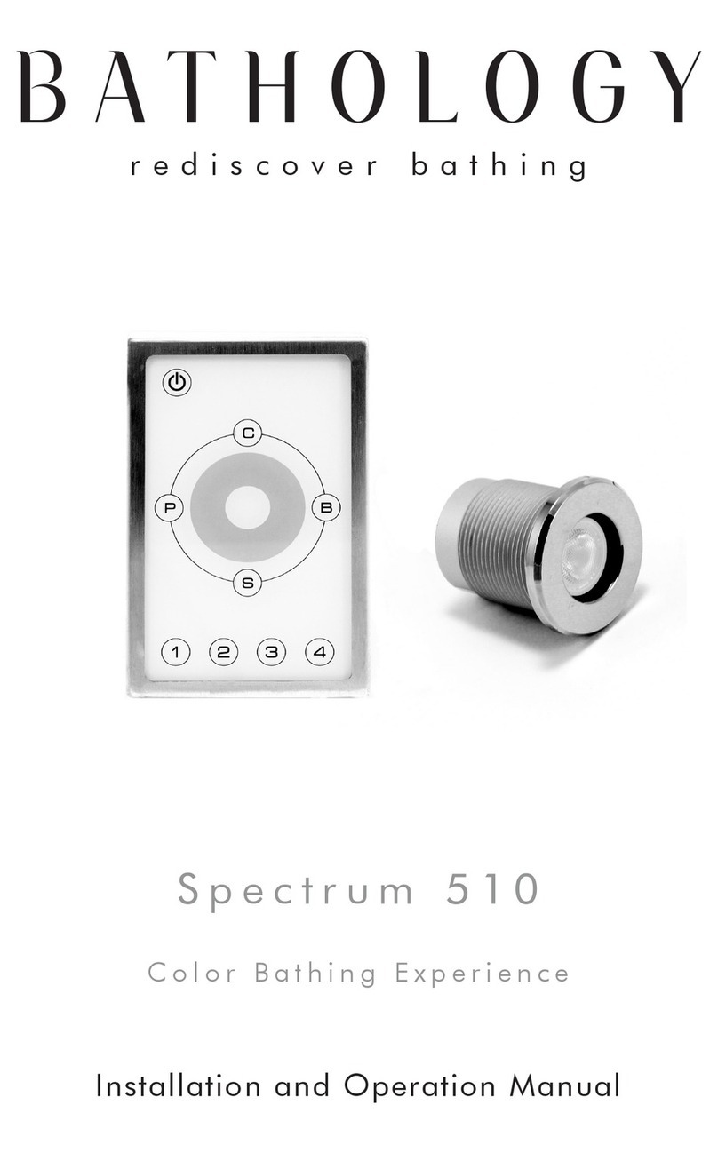
Bathology Spectrum 441 User manual

Bathology

Bathology Spectrum 441 User manual

Bathology Spectrum 350 User manual

Bathology

Bathology Spectrum 350 User manual

Bathology Spectrum 620-W User manual

Bathology

Bathology Spectrum 620-W User manual

Bathology Spectrum 510 User manual

Bathology

Bathology Spectrum 510 User manual

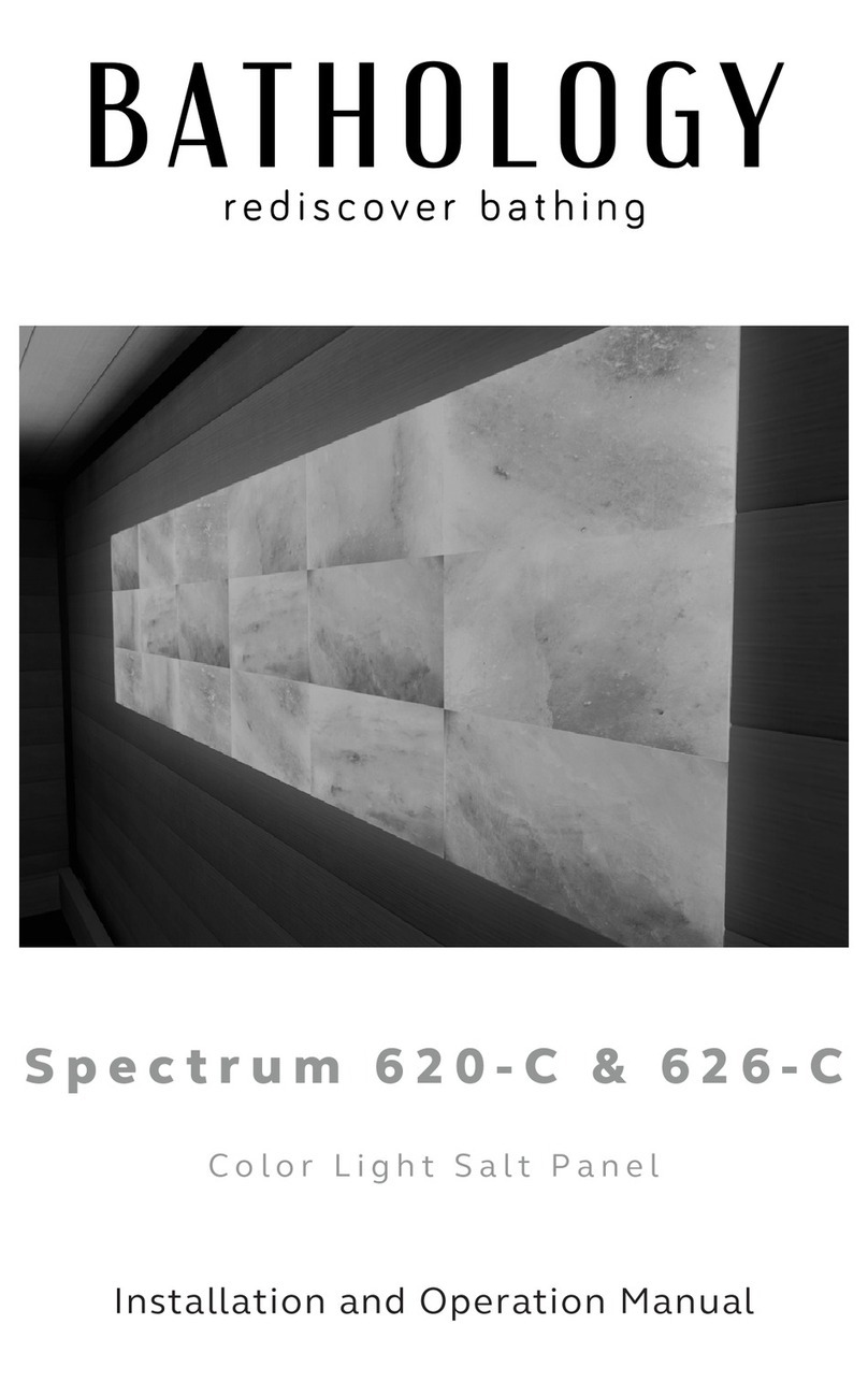
Bathology Spectrum 620-C User manual

Bathology

Bathology Spectrum 620-C User manual

Bathology Spectrum 441D User manual

Bathology

Bathology Spectrum 441D User manual

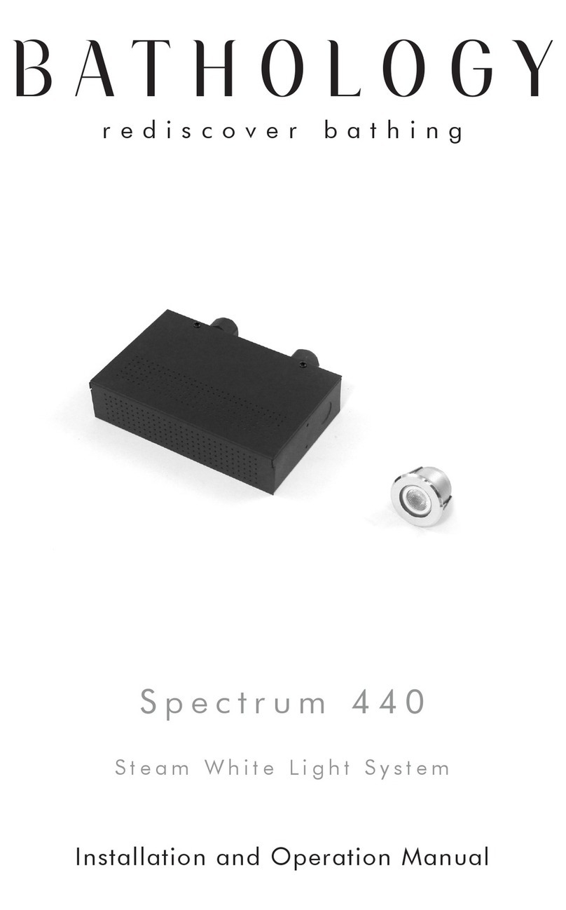
Bathology Spectrum 440 User manual

Bathology

Bathology Spectrum 440 User manual

Popular Lighting Equipment manuals by other brands

DAY 71285 instruction manual

DAY

DAY 71285 instruction manual

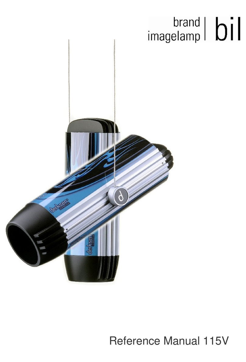
Derksen bil Reference manual

Derksen

Derksen bil Reference manual

WE-EF XRY300 LED Series Installation and maintenance instructions

WE-EF

WE-EF XRY300 LED Series Installation and maintenance instructions

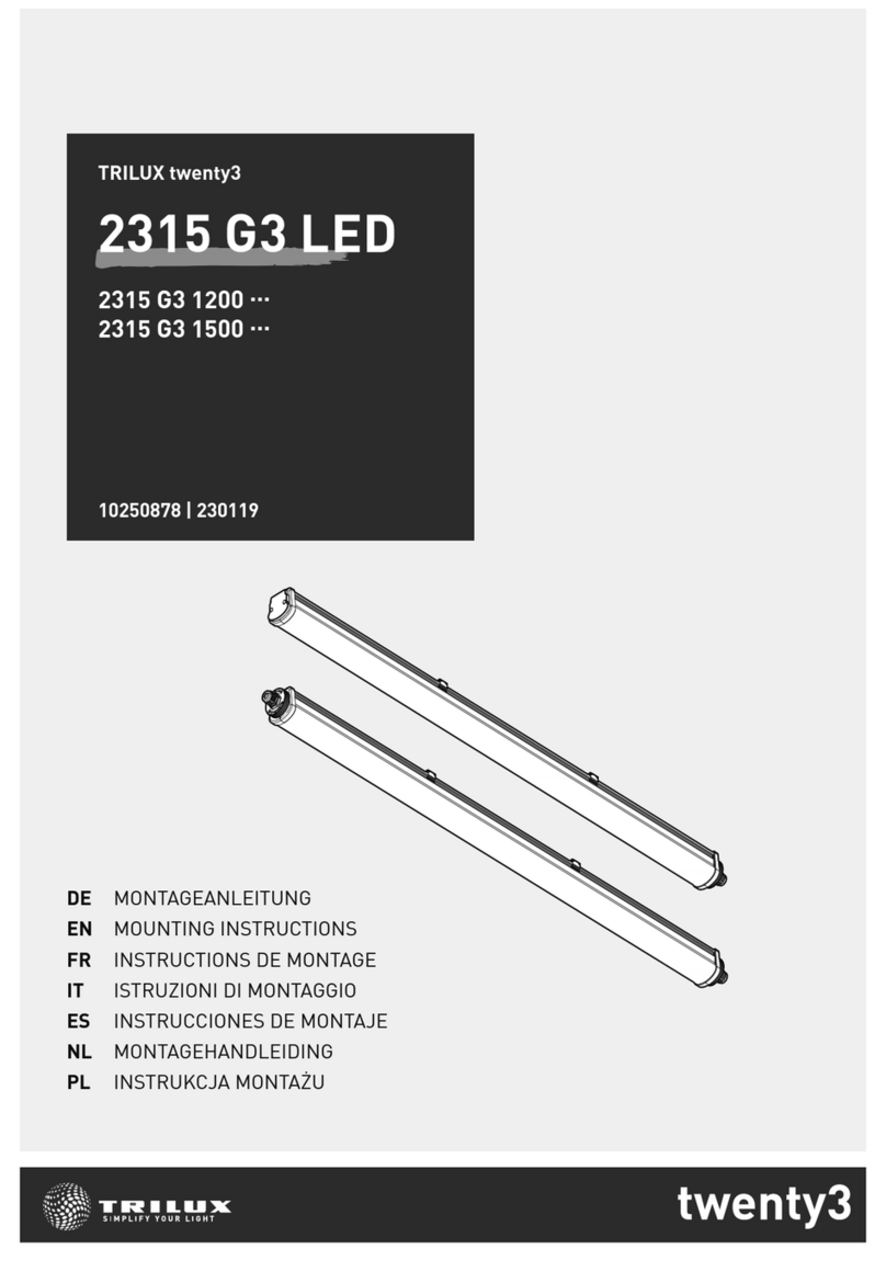
Trilux 2315 G3 LED Mounting instructions

Trilux

Trilux 2315 G3 LED Mounting instructions

Steren DIS-150 manual

Steren

Steren DIS-150 manual

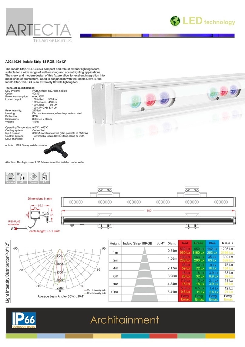
Artecta Indalo A0244024 Product sheet

Artecta

Artecta Indalo A0244024 Product sheet

Inventini PASCAL PILLARS user manual

Inventini

Inventini PASCAL PILLARS user manual

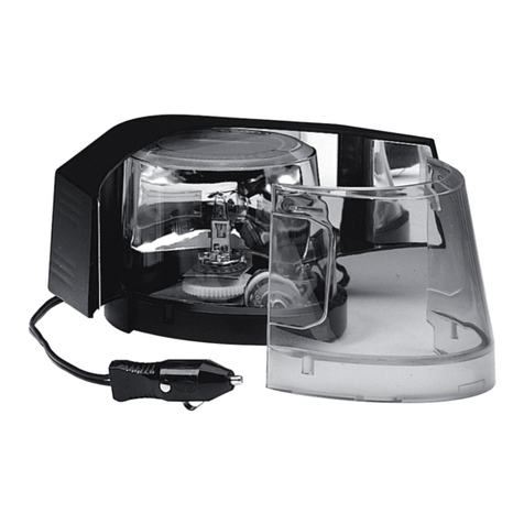
Code 3 DashLaser 660 Installation & operation manual

Code 3

Code 3 DashLaser 660 Installation & operation manual

COEF Sirio RAY 1200 02B014 operating instructions

COEF

COEF Sirio RAY 1200 02B014 operating instructions

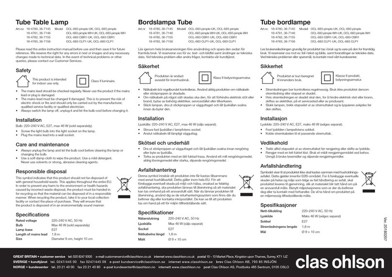
Clas Ohlson OCL-683 pimple-UK instruction manual

Clas Ohlson

Clas Ohlson OCL-683 pimple-UK instruction manual

ExPelec XLIGHT 100 LED user manual

ExPelec

ExPelec XLIGHT 100 LED user manual

influencer LED RINGLIGHT manual

influencer

influencer LED RINGLIGHT manual

BEARWARE 302520 manual

BEARWARE

BEARWARE 302520 manual

Ametrix ADY080112 installation instructions

Ametrix

Ametrix ADY080112 installation instructions

Sealife SeaDragon 4500 quick guide

Sealife

Sealife SeaDragon 4500 quick guide

Rosco RevoPro Operation manual

Rosco

Rosco RevoPro Operation manual

Whelen Engineering Company 97 Series installation manual

Whelen Engineering Company

Whelen Engineering Company 97 Series installation manual

Generac Mobile V20 owner's manual

Generac Mobile

Generac Mobile V20 owner's manual

manuals.online logo
manuals.online logoBrands
  • About & Mission
  • Contact us
  • Privacy Policy
  • Terms and Conditions

Copyright 2025 Manuals.Online. All Rights Reserved.