batterX LFP3500 User manual

TABLE OF CONTENTS
1. Safety instructions.................................................................................................................................................................................................................................1
Precautions..................................................................................................................................................................................................................................................1
Before connecting the device...................................................................................................................................................................................................1
Safety gear.................................................................................................................................................................................................................................................. 2
2. Introduction................................................................................................................................................................................................................................................3
3. Specifications............................................................................................................................................................................................................................................4
4. Device interface..................................................................................................................................................................................................................................... 5
5. Communication hub ..........................................................................................................................................................................................................................9
6. Safe handling..........................................................................................................................................................................................................................................10
Schematic diagram of the solution................................................................................................................................................................................10
Explanation of symbols.............................................................................................................................................................................................................10
7. Troubleshooting....................................................................................................................................................................................................................................11
Problem identification .................................................................................................................................................................................................................11
Actions .......................................................................................................................................................................................................................................................11
8. Emergency situations .....................................................................................................................................................................................................................12
Leaking batteries.............................................................................................................................................................................................................................12
Fire................................................................................................................................................................................................................................................................12
Wet batteries......................................................................................................................................................................................................................................12
Damaged batteries .......................................................................................................................................................................................................................12

batterx.io
1
V20.1
LFP3500
1. SAFETY INSTRUCTIONS
PRECAUTIONS
•It is important and necessary to read the Lithium Battery Module User's Manual thoroughly before installing
and using them. Neglecting the warnings or safety precautions may result in electric shock, serious injury or
death. Improper handling of the battery modules may also damage them or turning them unusable.
•It is recommended to charge the batteries within 12 hours of complete discharge.
•The battery modules have protection class IP20.
•Battery modules should only be exposed to temperatures of 0-45°C.
•Do not use a battery module that is damaged in any way.
•All battery connections must be disconnected prior to maintenance.
•It is forbidden to connect AC lines directly to the battery module.
•The built-in BMS is designed for 48V systems, do not connect these battery modules in series.
•Contact your supplier within 24 hours if anything unusual occurs.
•Do not use solvents to clean the battery.
•Do not expose the battery module to flames, aggressive chemicals, water or vapours.
•Do not paint the battery module. Neither internal nor external parts.
•Do not connect PV cables directly to the battery module.
•Ensure that the electrical parameters of the battery modules are compatible with the rest of the system.
•Do not open the battery modules.
•Do not use the batteries with faulty or incompatible inverters.
•It is forbidden to use these battery modules with other battery types.
•The warranty does not cover damage caused directly or indirectly by the items listed above.
•It is forbidden to insert any foreign parts into the openings of the battery module.
BEFORE CONNECTING THE DEVICE
•When unpacking, make sure that the product is intact and that all parts have been supplied. If this is not the
case, contact your supplier.
•Make sure that all cables to be connected are disconnected and that the battery modules are switched off.
•All cables must be connected correctly. Do not swap the positive and negative pole cables as this may cause
short circuits on the battery module and/or external devices.
•All battery modules must be grounded with a resistance of less than 1Ω.

batterx.io
2
V20.1
LFP3500
SAFETY GEAR
Use properly insulated tools to prevent accidental electric shock or short circuits.
It is recommended to wear the following protective equipment when handling the battery module:
Insulating gloves Safety Glasses Safety Shoes

batterx.io
3
V20.1
LFP3500
2. INTRODUCTION
The batterX LFP3500 is a lithium iron phosphate battery in the form of a 3.5kWh module. This module acts as a
reliable memory in a variety of applications. They contain their own integrated BMS, which monitors and
manages battery voltages, currents and cell information. The BMS also constantly adjusts all cell voltages to
each other, which further increases the service life of these modules. The LFP3500 is particularly suitable for
applications with high performance, small installation space, limited load capacity and long service life.
Multiple batteries can be connected in parallel to increase capacity and performance.
CHARATERISTICS
•Cathode material is made of LiFePO4 with safety performance and long life.
•The battery management system (BMS) has protection functions such as overcharging, overcurrent and
high/low temperature.
•The system can automatically manage the charge and discharge status, current and voltage of each cell.
•Flexible configuration, multiple battery modules can be connected in parallel to increase capacity and
performance.
•Adopted self-cooling mode quickly reduced the overall system noise.
•The module has a lower self-discharge, up to 6 months without charging, no memory effect, excellent low
charge and low discharge performance.
•The operating temperature ranges from -5°C to 50°C, (charging 0~50°C; discharging -10~50°C) with excellent
discharge performance and lifetime.
•Small size and light weight, standard 19-inch embedded design module is convenient for installation and
maintenance.

batterx.io
4
V20.1
LFP3500
3. SPECIFICATIONS
Basic Parameters
LFP3500
Nominal voltage (VDC)
48
Nominal power (Wh)
3552
Usable capacity (Wh)
3200
Dimension (mm)
442*420*132
Weight (Kg)
31
Discharge voltage (VDC)
44.5 ~ 53.5
Charging voltage (VDC)
52.5 ~ 53.5
Recommended charge/discharge current (A)
37
Max. charge/discharge current (A)
74
Peak charge/discharge current (A)
100A@15sec
Communication
RS232, RS485, CAN
Configuration (max. in 1 battery group)
8pcs
Operating temperature
0°C~50°C Charging
-5°C~50°C Discharge
Rack temperature
-20°C~60°C
Certification
TÜV / CE / UN38.3
Designed lifetime
10+ Years (25°C/77°F)
Cycle life
Up to 8000 (25°C)

batterx.io
5
V20.1
LFP3500
4. DEVICE INTERFACE
Power switch: to switching on and off the entire battery BMS, no power output. The LED below will light up,
when the switch is turned on.
Operation LED: Green LED lights to indicate that the battery module is running.
Alarm light: Red LED flashes to indicate that the battery is in alarm status. It lights continuously to indicate that
the battery is under protection.
SOC-LED's : 6 green LEDs to indicate the current capacity of the battery (see LED table)
Start button: Keep button pressed for more than 0.5s to start battery, power outputs are now active.
ADD Switch : 4 Dip Switches, Dip1 to set thebaud rate (0 is 115200, 1 is 9600). The lower position is
OFF, means "0". Upper position is ON, means "1". The settings are only active after the battery has
been restarted.
ON
OFF
Power switch
Run LED
Alarm LED
SOC LED
Start button
ADD Switch
batterx.io
6
V20.1
LFP3500
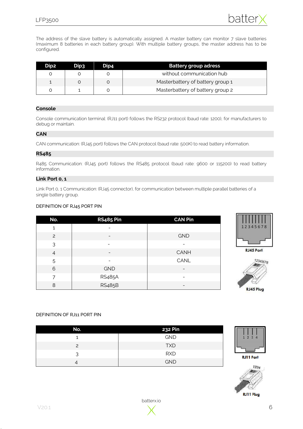
The address of the slave battery is automatically assigned. A master battery can monitor 7 slave batteries
(maximum 8 batteries in each battery group). With multiple battery groups, the master address has to be
configured.
Console communication terminal: (RJ11 port) follows the RS232 protocol (baud rate: 1200), for manufacturers to
debug or maintain.
CAN communication: (RJ45 port) follows the CAN protocol (baud rate: 500K) to read battery information.
R485 Communication: (RJ45 port) follows the RS485 protocol (baud rate: 9600 or 115200) to read battery
information.
Link Port 0, 1 Communication: (RJ45 connector), for communication between multiple parallel batteries of a
single battery group.
DEFINITION OF RJ45 PORT PIN
DEFINITION OF RJ11 PORT PIN
No.
232 Pin
1
GND
2
TXD
3
RXD
4
GND
Dip2
Dip3
Dip4
Battery group adress
0
0
0
without communication hub
1
0
0
Masterbattery of battery group 1
0
1
0
Masterbattery of battery group 2
No.
RS485 Pin
CAN Pin
1
-
2
-
GND
3
-
-
4
-
CANH
5
-
CANL
6
GND
-
7
RS485A
-
8
RS485B
-
Console
CAN
RS485
Link Port 0, 1

batterx.io
7
V20.1
LFP3500
Power connection cable: There are two pairs of terminals with the same function. One is for
connection to the system, the other one for parallel connection in-between battery groups. For
each individual module, each terminal can charge and discharge the battery module.
To remove the power connector, press and hold the lock button.
Terminal for dry contacts: 1 input and 3 potential-free outputs.
IN+
GND
NO1
COM1
NO2
COM2
NO3
COM3
Input
Wake up master battery, use 5-12VDC input, the circuit has a 10kΩ
resistance.
Output 1
on
Discharge on
off
Discharge off
Output 2
on
Charge on
off
Charge off
Output 3
on
System error
off
System normal
•Run LED: green, lights constantly when charging, flashing when discharging.
•ALARM LED: red, flashes on alarm and lights for long time in case of equipment failure or protection status.
•Battery capacity indicator: 6 green LED's, each lamp corresponds to 16.6% capacity.
•Standby: Only the power switch LED is on, the run LED lights up every 3,7s for 0,3s.
LED-STATUS
State
RUN
ALR
1
2
3
4
5
6
Power off
-
-
-
-
-
-
-
-
Power on
●
●
●
●
●
●
●
●
Standby
-
-
-
-
-
-
-
Charge
●
-
Display SOC; highest LED flash on: 0.5s / off: 0.5s
Discharging
Display SOC
Alarm
ALR: ; Other LEDs are as described above.
System
error/protection
-
●
-
-
-
-
-
-
●/●
ON
Flash, on: 0.3s ; off: 3.7s
/
Flash, on:0.5s ; off: 1.5s
Power Terminals
Dry contacts
LED Status Indicators

batterx.io
8
V20.1
LFP3500
BMS FUNKTION
Protection and Alarm
Management and Monitoring
Charging/discharging end
Cell balance
Charge overvoltage
Intelligent charging model
Discharge undervoltage
Charge/discharge current limit
Charging/Discharging Overcurrent
Capacity retention calculate
High/low temperature (cell/BMS)
Administrator Monitor
Short Circuit
Operation Record
Reverse polarity of the power cables

batterx.io
9
V20.1
LFP3500
5. COMMUNICATION HUB
The communication hub allows multiple battery groups to communicate with each other, thus increasing the
possible number of battery modules in an installation.
For communication again a RS485 Modbus is used, which is connected between ports 1/2 of the hub and the
RS485 socket of the respective master module.

batterx.io
10
V20.1
LFP3500
6. SAFE HANDLING
SCHEMATIC DIAGRAM OF THE SOLUTION
EXPLANATION OF SYMBOLS
batterx.io
11
V20.1
LFP3500
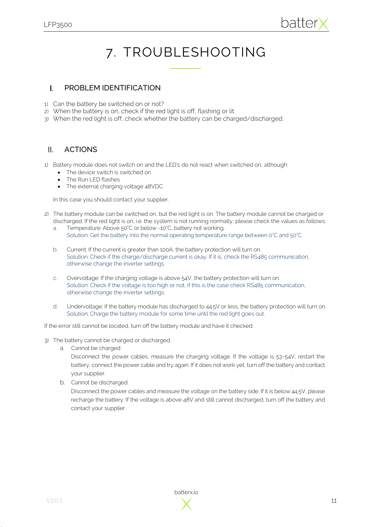
7. TROUBLESHOOTING
PROBLEM IDENTIFICATION
1) Can the battery be switched on or not?
2) When the battery is on, check if the red light is off, flashing or lit.
3) When the red light is off, check whether the battery can be charged/discharged.
ACTIONS
1) Battery module does not switch on and the LED's do not react when switched on, although:
•The device switch is switched on
•The Run LED flashes
•The external charging voltage 48VDC
In this case you should contact your supplier.
2) The battery module can be switched on, but the red light is on. The battery module cannot be charged or
discharged. If the red light is on, i.e. the system is not running normally, please check the values as follows:
a. Temperature: Above 50°C or below -10°C, battery not working.
Solution: Get the battery into the normal operating temperature range between 0°C and 50°C.
b. Current: If the current is greater than 100A, the battery protection will turn on.
Solution: Check if the charge/discharge current is okay. If it is, check the RS485 communication,
otherwise change the inverter settings.
c. Overvoltage: If the charging voltage is above 54V, the battery protection will turn on.
Solution: Check if the voltage is too high or not, if this is the case check RS485 communication,
otherwise change the inverter settings.
d. Undervoltage: If the battery module has discharged to 44.5V or less, the battery protection will turn on.
Solution: Charge the battery module for some time until the red light goes out.
If the error still cannot be located, turn off the battery module and have it checked.
3) The battery cannot be charged or discharged.
a. Cannot be charged:
Disconnect the power cables, measure the charging voltage. If the voltage is 53~54V, restart the
battery, connect the power cable and try again. If it does not work yet, turn off the battery and contact
your supplier.
b. Cannot be discharged:
Disconnect the power cables and measure the voltage on the battery side. If it is below 44.5V, please
recharge the battery. If the voltage is above 48V and still cannot discharged, turn off the battery and
contact your supplier.

batterx.io
12
V20.1
LFP3500
8. EMERGENCY SITUATIONS
LEAKING BATTERIES
If electrolyte leaks from the battery, avoid contact with the leaking liquid or gas. If you are exposed to the
leaking substance, immediately take the following steps.
Inhalation: Evacuate the contaminated area and seek medical attention.
Contact with eyes: Rinse eyes with running water for 15 minutes and seek medical attention.
Contact with skin: Wash affected area thoroughly with soap and water and seek medical attention.
Ingestion: Induce vomiting and seek medical attention.
FIRE
NO WATER! Only a dry powder fire extinguisher may be used; if possible, move the battery pack to a safe area
before catching fire.
WET BATTERIES
If the battery has become wet or fallen into water, keep it out of the reach of others and contact your business
partner or installer for technical support.
DAMAGED BATTERIES
Damaged batteries are dangerous and must be handled with the utmost care. They are not suitable for use
and may present a danger to persons or property. If the battery appears to be damaged, pack it in its original
packing and return it to your installer or business partner.
HINT
Damaged batteries can leak electrolyte or produce flammable gas. In the event of such damage, please
contact your installer or business partner.
Table of contents
Other batterX Batteries Pack manuals


