batterX HOME 2.0 h10R-7 User manual


batterx.de
Benutzerhandbuch
user manual
1
V21.1
SAFETY INSTRUCTIONS
H10-Inverter
Before using the system, read all instructions and safety information on the inverter and in this manual.
Keep this manual easily accessible near the inverter.
This manual is intended for qualified personnel. The tasks described here should only be completed by such
qualified personnel.
WARNING! Read all instructions and safety information before installing the inverter.
WARNING! The device should be properly (and in accordance with local laws) grounded, otherwise,
in case of malfunction, the inverters case might be under voltage.
WARNING! The inverter is heavy and should be carried by 2 persons.
CAUTION! To avoid the risk of electric shock, the service technician should disconnect all AC
and DC power sources from the system and check for possible dangerous voltages before
starting any work on the system. Simply switching off the device does not reduce the risk!
The internal capacitors can remain charged for up to 5 minutes after the power sources have
been switched off.
CAUTION! Do not disassemble the inverter yourself. It does not contain any parts that may
be serviced or replaced by the user. Servicing the inverter yourself carries the risk of electric
shock or burns. In addition, a non-authorized opening of the inverter case, will forfeit the
manufacturer's warranty.
CAUTION! To avoid the risk of electric shock and fire, make sure that the wiring around the
system is in proper condition and not undersized. Do not operate the inverter with damaged
or undersized cables.
CAUTION! At high ambient temperatures, the surface of the inverter can become so warm that it can
cause skin burns if accidentally touched. The inverter should therefore not be installed in a heavily
frequented environment.
CAUTION! Only use suitable material and tools! Other unsuitable materials or tools may
result in fire, electric shock or personal injury.
CAUTION! To reduce the risk of fire, the air circulation and the inverter fans must not be obstructed or
blocked.
CAUTION! Do not use the inverter if it has been struck, dropped or damaged otherwise. If the inverter
is damaged, contact your supplier.
CAUTION! All AC, DC and battery fuses are used to switch off energy sources and should therefore
be always easily accessible.
batterx.de
Benutzerhandbuch
user manual
2
V21.1
SYMBOL-LEGEND
Refers to the installation instructions.
Danger
Risk of electric shock
Risk of electric shock. Discharge time of the internal residual charge 5 min.
Hot Surface
Battery Module
PRECAUTIONS
•It is important and necessary to read the Lithium Battery Module User's Manual thoroughly before
installing and using them. Neglecting the warnings or safety precautions may result in electric shock,
serious injury or death. Improper handling of the battery modules may also damage them or turning them
unusable.
•It is recommended to charge the batteries within 12 hours of complete discharge.
•The battery modules are IP20 rated.
•Battery modules should only be exposed to temperatures of 0-45°C.
•Do not use a battery module that is damaged in any way.
•All battery connections must be disconnected prior to maintenance.
•It is forbidden to connect AC lines directly to the battery module.
•The built-in BMS is designed for 48V systems, do not connect these battery modules in series.
•Contact your supplier within 24 hours if anything unusual occurs.
•Do not use solvents to clean the battery.
•Do not expose the battery module to flames, aggressive chemicals, water or vapours.
•Do not paint the battery module. Neither internal nor external parts.
•Do not connect PV cables directly to the battery module.
•Ensure that the electrical parameters of the battery modules are compatible with the rest of the system
equipment.
•Do not open the battery modules.
•Do not use the batteries with faulty or incompatible inverters.
•It is forbidden to use these battery modules with other battery types.
•The warranty does not cover damage caused directly or indirectly by the items listed above.
•It is forbidden to insert any foreign parts into the openings of the battery module.
BEFORE CONNECTING THE DEVICE
•When unpacking, make sure that the product is intact and that all parts have been supplied. If this is not
the case, contact your supplier.
•Make sure that all cables to be connected are disconnected and that the battery modules are switched off.
•All cables must be connected correctly. Do not swap the positive and negative pole cables as this may
cause short circuits on the battery module and/or external devices.
•All battery modules must be grounded with a resistance of less than 1Ω.

batterx.de
Benutzerhandbuch
user manual
3
V21.1
IN USE
•If the battery module is to be removed, the battery module must be completely disconnected from the
system and switched off.
•In case of fire, only dry powder fire extinguishers are allowed. Fire extinguishing with liquid extinguishing
agents is prohibited.
•Opening, repairing and disassembling the battery modules is strictly prohibited. We accept no
responsibility for the consequences of non-compliance with the safety instructions or of manipulation or
alteration of the battery modules.
Other
Conversion or modification of the system should only be carried out by trained specialist personnel.
Unauthorized modifications may have the following effects:
•Electric shock
•Injuries
•System malfunctions
•System outage
•Loss of warranty
If a circuit breaker or other fuses trip, you should first find out the cause of the trip before switching it on again.
If in doubt, contact your installer.
The rack cabinet of the system should be placed on a flat surface. The cabinet brakes should also be locked
to prevent unexpected movement.
batterx.de
Benutzerhandbuch
user manual
4
V21.1
EMERGENCY SITUATIONS
I. Leaking Batteries
If electrolyte leaks from the battery, avoid contact with the leaking liquid or gas. If you are exposed to the
leaking substance, immediately take the following steps. Inhalation: Evacuate the contaminated area and seek
medical attention. Contact with eyes: Rinse eyes with running water for 15 minutes and seek medical attention.
Contact with skin: Wash affected area thoroughly with soap and water and seek medical attention. Oral
ingestion: Induce vomiting and seek medical attention.
II. Fire
NO WATER! Only a fire extinguisher with dry powder filling may be used; if possible, move the battery pack to
a safe area before it catches fire.
III. Wet Batteries
If the battery has become wet or fallen into water, keep it out of the reach of others and contact your installer
or an authorized dealer for technical support.
IV. Damaged Batteries
Damaged batteries are dangerous and must be handled with the utmost care. They are not suitable for use
and may present a danger to persons or property. If the battery appears to be damaged, pack it in its original
container and return it to your installer or authorized dealer.
Note
Damaged batteries can leak electrolyte or produce combustible gas. In the event of such damage, please
contact your installer.
batterx.de
Benutzerhandbuch
user manual
5
V21.1
TABLE OF CONTENTS
1. System Operation.............................................................................................................................................................................6
I. System structure............................................................................................................................................................................6
H10-Inverter............................................................................................................................................................................................6
Clix ModulE............................................................................................................................................................................................. 7
Battery Modules.................................................................................................................................................................................8
II. Handling .................................................................................................................................................................................................8
Shut down and Switch off.........................................................................................................................................................8
Start up and Switching On ........................................................................................................................................................9
2. liveX Portal.............................................................................................................................................................................................10
I. Introduction .......................................................................................................................................................................................10
II. Description ..........................................................................................................................................................................................11
III. Overview of the Portal.............................................................................................................................................................13
IV. System Dashboard.....................................................................................................................................................................14
H10-Inverter:.........................................................................................................................................................................................17
Outputs: ....................................................................................................................................................................................................17
Inputs:.........................................................................................................................................................................................................18
V. System Settings.............................................................................................................................................................................19
VI. Portal Settings................................................................................................................................................................................20
VII. History .................................................................................................................................................................................................... 21
VIII.Service .................................................................................................................................................................................................. 23
IX. logout..................................................................................................................................................................................................... 24
X. Batterx Livex –App................................................................................................................................................................... 24
batterx.de
Benutzerhandbuch
user manual
6
V21.1
1.SYSTEM OPERATION
I. SYSTEM STRUCTURE
The batterX complete system consists of several individual components. In this chapter, we will show the
most important individual parts and briefly explain their technical function and handling.
The essential elements of the system are:
•H10 inverter
•cliX module
•battery modules
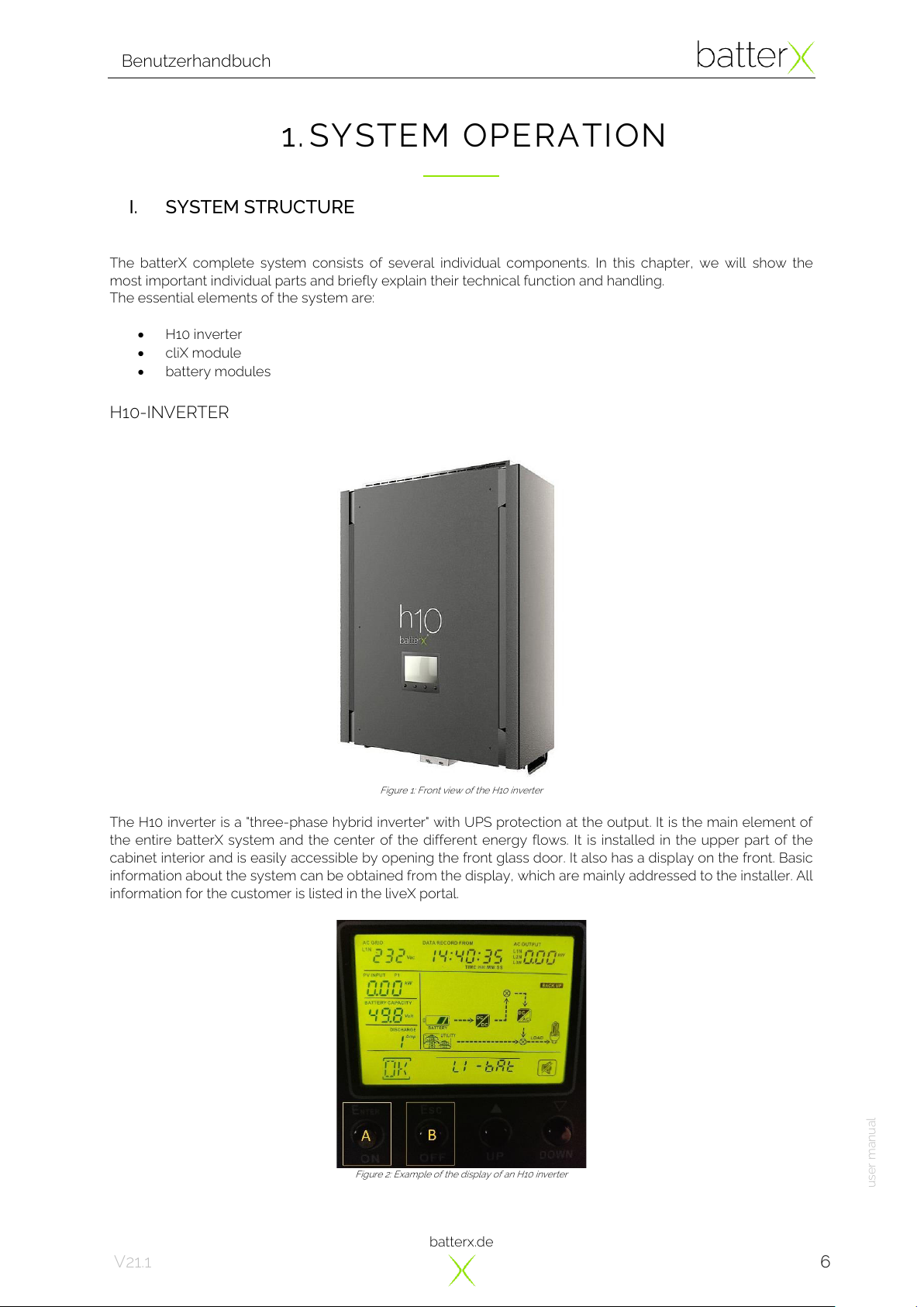
H10-INVERTER
Figure 1: Front view of the H10 inverter
The H10 inverter is a "three-phase hybrid inverter" with UPS protection at the output. It is the main element of
the entire batterX system and the center of the different energy flows. It is installed in the upper part of the
cabinet interior and is easily accessible by opening the front glass door. It also has a display on the front. Basic
information about the system can be obtained from the display, which are mainly addressed to the installer. All
information for the customer is listed in the liveX portal.
Figure 2: Example of the display of an H10 inverter

batterx.de
Benutzerhandbuch
user manual
7
V21.1
CLIX MODULE
Figure 3: Front view of the cliX module
The cliX module is the center of the batterX system, which can be divided into three sections:
Connection, security and intelligence.
The module establishes the connection between all components in a practical and intelligent way so that they
can work together perfectly. However, the knowledge of these connections is only necessary for the installer
and is not described here.
With the cliX module batterX sets new standards in terms of security. The module combines all safety
components to a whole and thus ensures a high security standard of the entire system. All electrical lines of
the entire system are additionally protected and monitored.
Furthermore, the entire hardware of the liveX monitoring is built into the cliX module.
In the following points we describe the most important components of the cliX module and their function:
1. Battery module fuses 1-4
Each battery module has its own circuit breaker. The battery circuit breaker is switched ON when the
actuator lever is at the top and the status indicator is coloured red. They are switched OFF when the
actuator lever is at the bottom and the status indicator is coloured green. When the circuit breaker is
switched OFF, the circuit of the respective battery module is interrupted.
2. Photovoltaic input fuse 1-4
Each photovoltaic input has its own circuit breaker protection. The operating states are the same as
for the battery module circuit breakers. When the circuit breaker is switched OFF, the circuit of the
respective photovoltaic input is interrupted.
3. LiveX power supply
The liveX hardware is connected separately to a power supply that has its own circuit breaker
protection. The operating states are the same as for the battery module circuit breakers.
When the circuit breaker is switched OFF, the power supply circuit is interrupted and the liveX is
switched OFF too.
4. Residual current circuit breaker (RCCB)
The output of the system has a residual current circuit breaker which ensures personal protection in
the event of residual currents. It is switched ON when the actuator lever is up and switched OFF when
the actuator lever is down. When the RCCB is switched OFF, the output of the system is switched
OFF too.
5. Bypass signal light
If the output of the H10 inverter is switched OFF manually, the system switches ON the automatic
bypass. This automatic bypass connects the system input (AC input) to the system output (AC output)
so that the H10 inverter is disconnected from the system.
6. Overvoltage protection of the photovoltaic inputs (SPD)
The SPD (surge protection device) protects the system against over voltages on the photovoltaic side.
If one of the status indicators is coloured red, the respective module must be replaced.
1
2
6
4
3
5
batterx.de
Benutzerhandbuch
user manual
8
V21.1
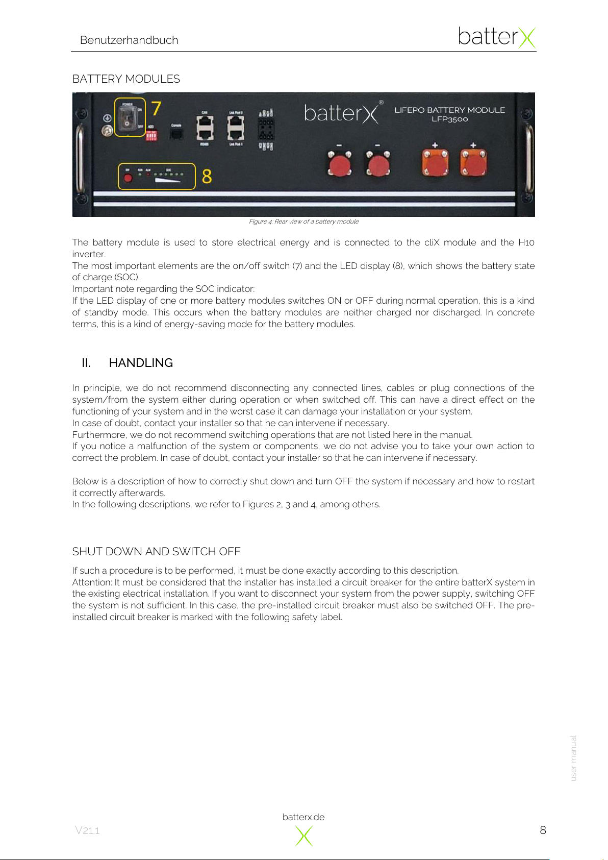
BATTERY MODULES
Figure 4: Rear view of a battery module
The battery module is used to store electrical energy and is connected to the cliX module and the H10
inverter.
The most important elements are the on/off switch (7) and the LED display (8), which shows the battery state
of charge (SOC).
Important note regarding the SOC indicator:
If the LED display of one or more battery modules switches ON or OFF during normal operation, this is a kind
of standby mode. This occurs when the battery modules are neither charged nor discharged. In concrete
terms, this is a kind of energy-saving mode for the battery modules.
II. HANDLING
In principle, we do not recommend disconnecting any connected lines, cables or plug connections of the
system/from the system either during operation or when switched off. This can have a direct effect on the
functioning of your system and in the worst case it can damage your installation or your system.
In case of doubt, contact your installer so that he can intervene if necessary.
Furthermore, we do not recommend switching operations that are not listed here in the manual.
If you notice a malfunction of the system or components, we do not advise you to take your own action to
correct the problem. In case of doubt, contact your installer so that he can intervene if necessary.
Below is a description of how to correctly shut down and turn OFF the system if necessary and how to restart
it correctly afterwards.
In the following descriptions, we refer to Figures 2, 3 and 4, among others.
SHUT DOWN AND SWITCH OFF
If such a procedure is to be performed, it must be done exactly according to this description.
Attention: It must be considered that the installer has installed a circuit breaker for the entire batterX system in
the existing electrical installation. If you want to disconnect your system from the power supply, switching OFF
the system is not sufficient. In this case, the pre-installed circuit breaker must also be switched OFF. The pre-
installed circuit breaker is marked with the following safety label.
batterx.de
Benutzerhandbuch
user manual
9
V21.1
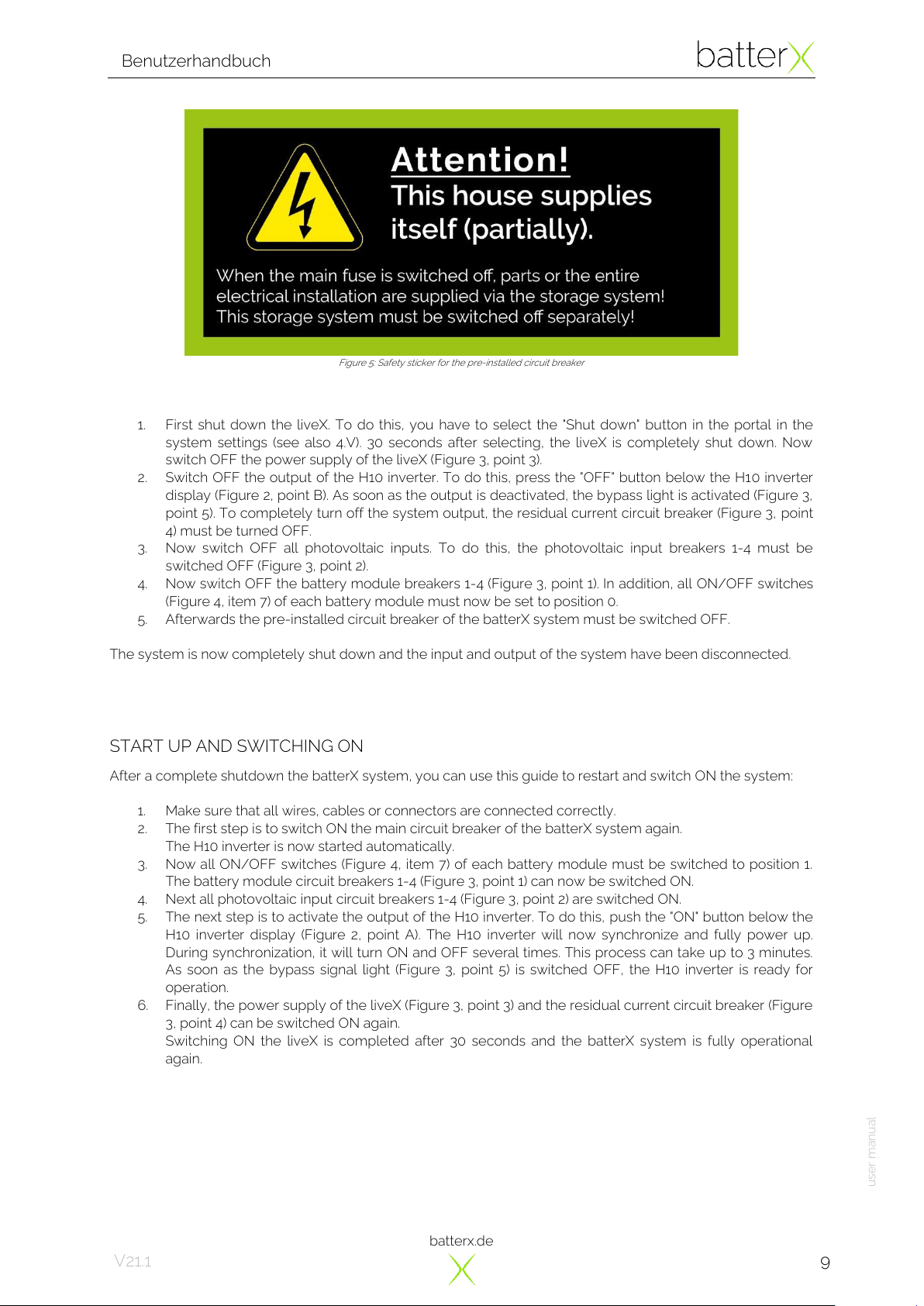
Figure 5: Safety sticker for the pre-installed circuit breaker
1. First shut down the liveX. To do this, you have to select the "Shut down" button in the portal in the
system settings (see also 4.V). 30 seconds after selecting, the liveX is completely shut down. Now
switch OFF the power supply of the liveX (Figure 3, point 3).
2. Switch OFF the output of the H10 inverter. To do this, press the "OFF" button below the H10 inverter
display (Figure 2, point B). As soon as the output is deactivated, the bypass light is activated (Figure 3,
point 5). To completely turn off the system output, the residual current circuit breaker (Figure 3, point
4) must be turned OFF.
3. Now switch OFF all photovoltaic inputs. To do this, the photovoltaic input breakers 1-4 must be
switched OFF (Figure 3, point 2).
4. Now switch OFF the battery module breakers 1-4 (Figure 3, point 1). In addition, all ON/OFF switches
(Figure 4, item 7) of each battery module must now be set to position 0.
5. Afterwards the pre-installed circuit breaker of the batterX system must be switched OFF.
The system is now completely shut down and the input and output of the system have been disconnected.
START UP AND SWITCHING ON
After a complete shutdown the batterX system, you can use this guide to restart and switch ON the system:
1. Make sure that all wires, cables or connectors are connected correctly.
2. The first step is to switch ON the main circuit breaker of the batterX system again.
The H10 inverter is now started automatically.
3. Now all ON/OFF switches (Figure 4, item 7) of each battery module must be switched to position 1.
The battery module circuit breakers 1-4 (Figure 3, point 1) can now be switched ON.
4. Next all photovoltaic input circuit breakers 1-4 (Figure 3, point 2) are switched ON.
5. The next step is to activate the output of the H10 inverter. To do this, push the "ON" button below the
H10 inverter display (Figure 2, point A). The H10 inverter will now synchronize and fully power up.
During synchronization, it will turn ON and OFF several times. This process can take up to 3 minutes.
As soon as the bypass signal light (Figure 3, point 5) is switched OFF, the H10 inverter is ready for
operation.
6. Finally, the power supply of the liveX (Figure 3, point 3) and the residual current circuit breaker (Figure
3, point 4) can be switched ON again.
Switching ON the liveX is completed after 30 seconds and the batterX system is fully operational
again.
batterx.de
Benutzerhandbuch
user manual
10
V21.1
2.LIVEX PORTAL
I. INTRODUCTION
The “liveX”is the innovative software of batterX, which allows unlimited monitoring, controlling and reading of
the different batterX systems.
The liveX is an in-house, cloud-based system, which enables worldwide secure access to all devices. It is
divided into several user levels, so that there are different functions and possibilities between the individual
levels.
Each installer as well as each end customer gets a separate access to his liveX portal. This access is defined
and monitored by batterX. It is possible to assign several devices to a single customer account so that
handling is as easy as possible.
Please note that only the systems defined or activated by batterX can work with the liveX software. It is not
possible to freely combine the individual systems.
The liveX hardware is located in the cliX module as standard, which is not accessible from the outside and
therefore optimally protected. All required interfaces of the liveX are mounted on the back of the cliX module.
This guarantees an efficient and practical connection of the individual connections.
batterX also provides the liveX App for mobile devices (Android), which enables an easier operation on these
devices. You can download the app from your Google Play Store.
In this manual we explain the handling of liveX and describe the individual areas, functions, and details. Some
technical aspects are also explained. In addition, we provide insights into the possibilities that can be realized
with this system.

batterx.de
Benutzerhandbuch
user manual
11
V21.1
II. DESCRIPTION
Every end customer of a batterX Home Series system gets his own official access (customer level) to the liveX
portal. When the system is installed, the customer account is automatically created by the installer. For this
reason, the installer needs the e-mail address of the respective end customer. After the installation, the end
customer receives a message on his e-mail account. The e-mail contains a link to activate the account.
Figure 6: Example of an e-mail to activate the customer account
As described in the e-mail, the link must be opened to activated the account. The customer's login data (e-
mail address and password) are listed again in the message. Once the account has been activated, the
customer will receive a confirmation.
Figure 7: Confirmation of the correct activation of the customer account
After activation, the customer can now access his liveX account with his login data. It is recommended to
change the default password in the settings.
As already mentioned, there are several access levels in the liveX Portal. The higher the access level, the
more settings and options are available. In this case, the installer level is higher than the end user level.
batterx.de
Benutzerhandbuch
user manual
12
V21.1
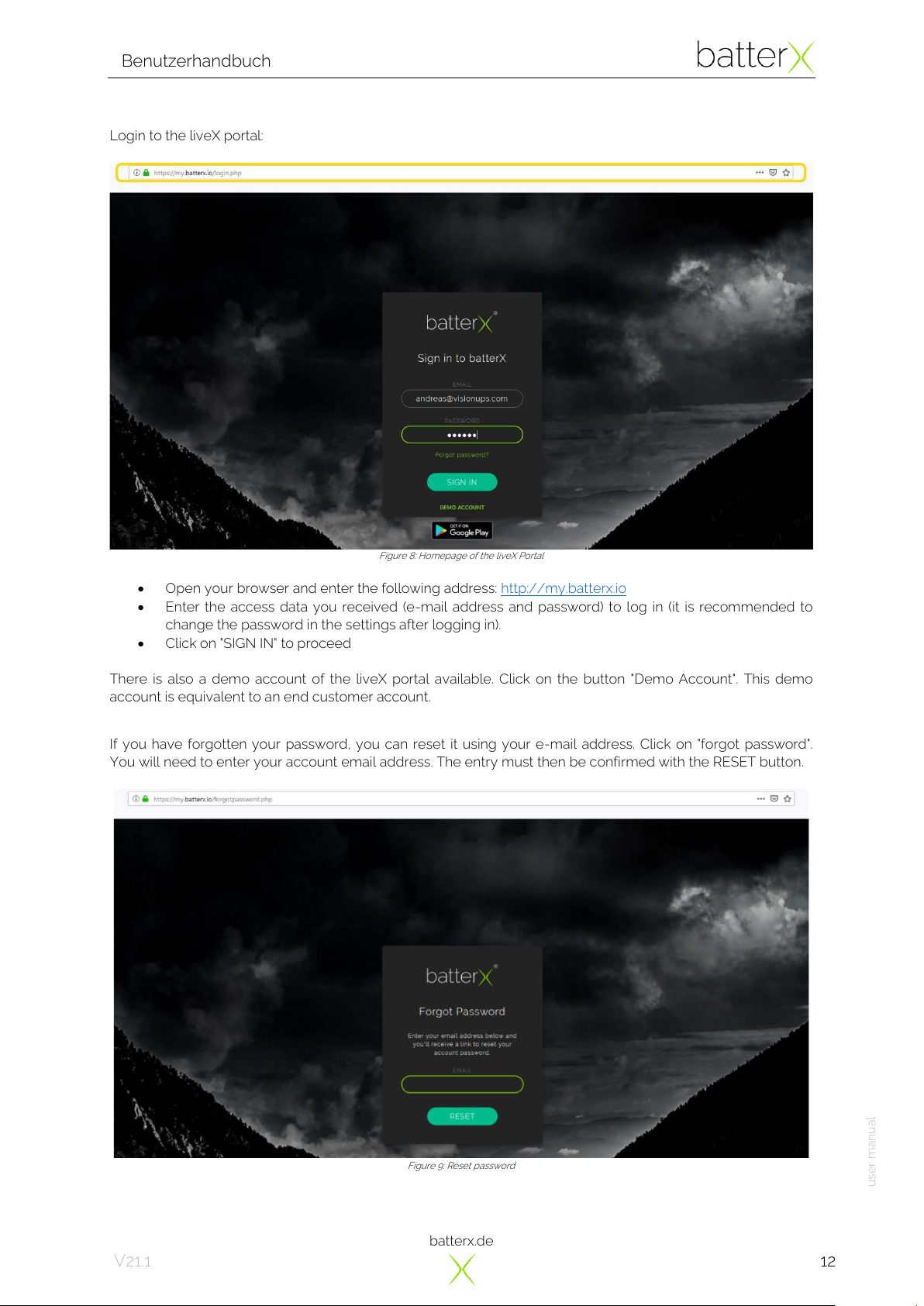
Login to the liveX portal:
Figure 8: Homepage of the liveX Portal
•Open your browser and enter the following address: http://my.batterx.io
•Enter the access data you received (e-mail address and password) to log in (it is recommended to
change the password in the settings after logging in).
•Click on "SIGN IN" to proceed
There is also a demo account of the liveX portal available. Click on the button "Demo Account". This demo
account is equivalent to an end customer account.
If you have forgotten your password, you can reset it using your e-mail address. Click on "forgot password".
You will need to enter your account email address. The entry must then be confirmed with the RESET button.
Figure 9: Reset password

batterx.de
Benutzerhandbuch
user manual
13
V21.1
In short time you will receive an e-mail with a link that can be accessed by clicking on it. Now it is possible to
enter a new password which will by replace the old one. With the confirmation it is completed and the
password has been successfully changed.
III. OVERVIEW OF THE PORTAL
After logging in to the liveX portal, you are at the system overview of all devices owned by the same end
customer. In the upper search field, each system can be searched quickly and easily.
The following search criteria can be used:
•System serial number
•Serial number of the H10 inverter
•Serial number of the liveX
•Type of inverter (for example “H10”)
•Name of end customer/owner
•Address of the end customer/installation
•country of installation
Figure 10: System overview of all registered systems of the same end customer
The overview of all systems gives an impression of the main states of the units. With the mouse, the details of
the different icons below each system can be called up.
The following information is displayed by the icons:
•Latest timestamp
•Battery condition
•Active warnings
•Software update
Depending on the importance, the colour of the icon changes (white, orange, red).
batterx.de
Benutzerhandbuch
user manual
14
V21.1
IV. SYSTEM DASHBOARD
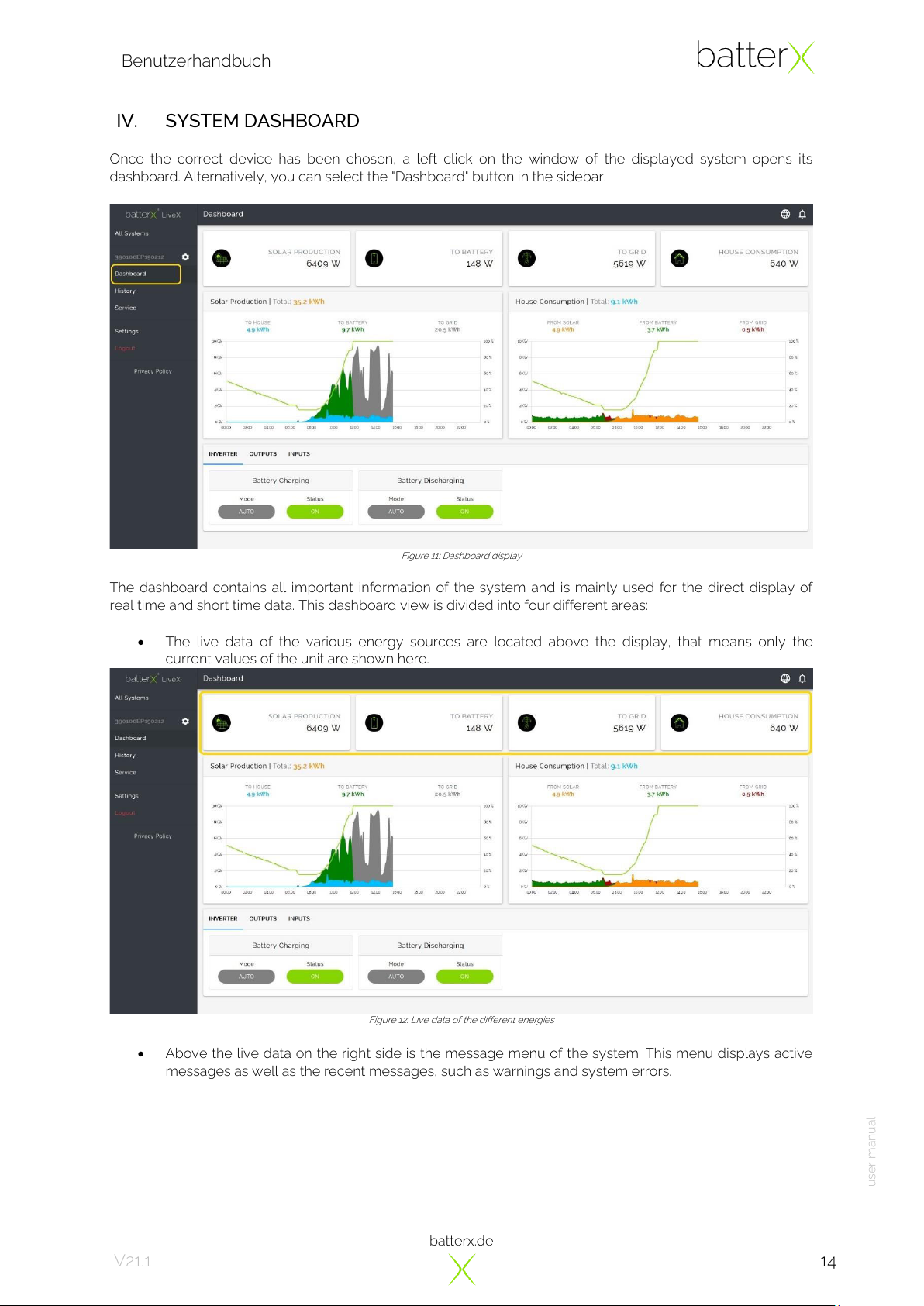
Once the correct device has been chosen, a left click on the window of the displayed system opens its
dashboard. Alternatively, you can select the "Dashboard" button in the sidebar.
Figure 11: Dashboard display
The dashboard contains all important information of the system and is mainly used for the direct display of
real time and short time data. This dashboard view is divided into four different areas:
•The live data of the various energy sources are located above the display, that means only the
current values of the unit are shown here.
Figure 12: Live data of the different energies
•Above the live data on the right side is the message menu of the system. This menu displays active
messages as well as the recent messages, such as warnings and system errors.
batterx.de
Benutzerhandbuch
user manual
15
V21.1
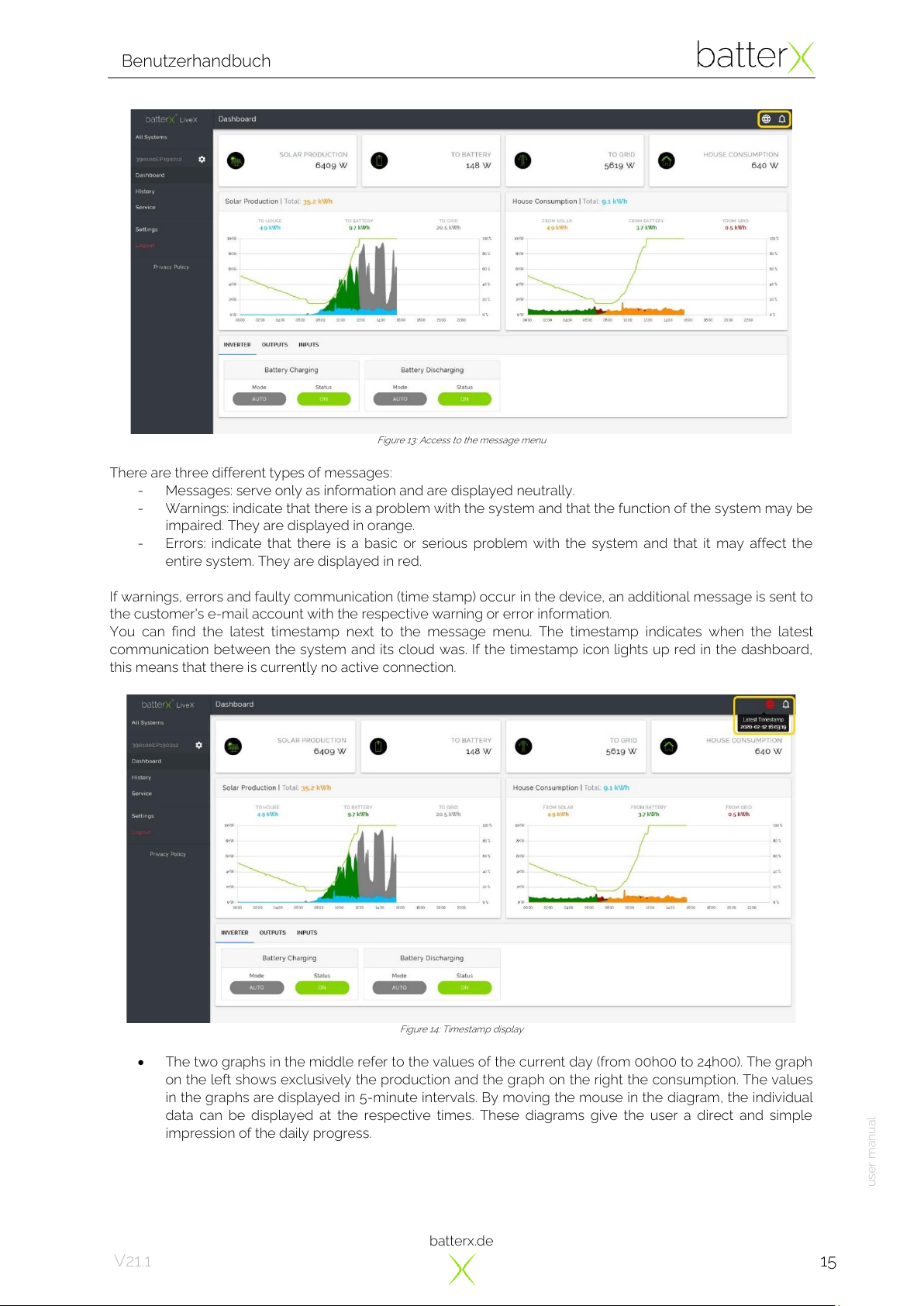
Figure 13: Access to the message menu
There are three different types of messages:
-Messages: serve only as information and are displayed neutrally.
-Warnings: indicate that there is a problem with the system and that the function of the system may be
impaired. They are displayed in orange.
-Errors: indicate that there is a basic or serious problem with the system and that it may affect the
entire system. They are displayed in red.
If warnings, errors and faulty communication (time stamp) occur in the device, an additional message is sent to
the customer's e-mail account with the respective warning or error information.
You can find the latest timestamp next to the message menu. The timestamp indicates when the latest
communication between the system and its cloud was. If the timestamp icon lights up red in the dashboard,
this means that there is currently no active connection.
Figure 14: Timestamp display
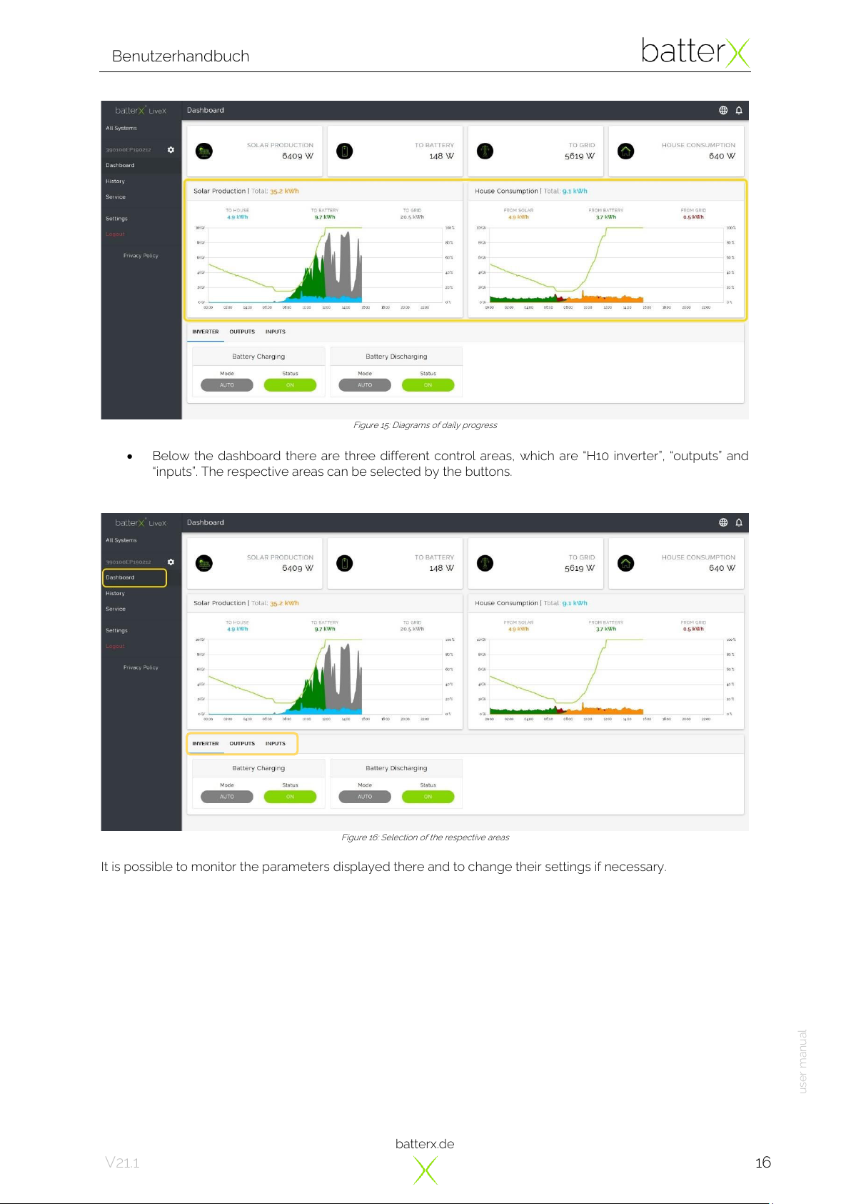
•The two graphs in the middle refer to the values of the current day (from 00h00 to 24h00). The graph
on the left shows exclusively the production and the graph on the right the consumption. The values
in the graphs are displayed in 5-minute intervals. By moving the mouse in the diagram, the individual
data can be displayed at the respective times. These diagrams give the user a direct and simple
impression of the daily progress.
batterx.de
Benutzerhandbuch
user manual
16
V21.1
Figure 15: Diagrams of daily progress
•Below the dashboard there are three different control areas, which are “H10 inverter”, “outputs”and
“inputs”. The respective areas can be selected by the buttons.
Figure 16: Selection of the respective areas
It is possible to monitor the parameters displayed there and to change their settings if necessary.
batterx.de
Benutzerhandbuch
user manual
17
V21.1
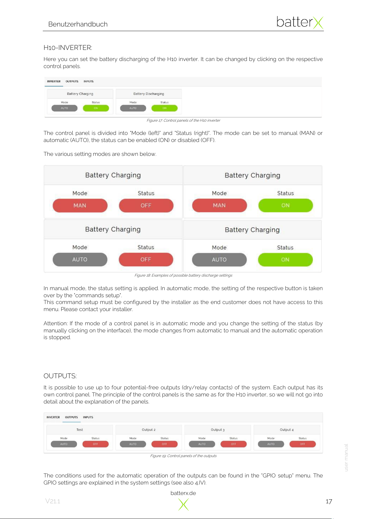
H10-INVERTER:
Here you can set the battery discharging of the H10 inverter. It can be changed by clicking on the respective
control panels.
Figure 17: Control panels of the H10 inverter
The control panel is divided into "Mode (left)" and "Status (right)". The mode can be set to manual (MAN) or
automatic (AUTO), the status can be enabled (ON) or disabled (OFF).
The various setting modes are shown below.
Figure 18: Examples of possible battery discharge settings
In manual mode, the status setting is applied. In automatic mode, the setting of the respective button is taken
over by the "commands setup".
This command setup must be configured by the installer as the end customer does not have access to this
menu. Please contact your installer.
Attention: If the mode of a control panel is in automatic mode and you change the setting of the status (by
manually clicking on the interface), the mode changes from automatic to manual and the automatic operation
is stopped.
OUTPUTS:
It is possible to use up to four potential-free outputs (dry/relay contacts) of the system. Each output has its
own control panel. The principle of the control panels is the same as for the H10 inverter, so we will not go into
detail about the explanation of the panels.
Figure 19: Control panels of the outputs
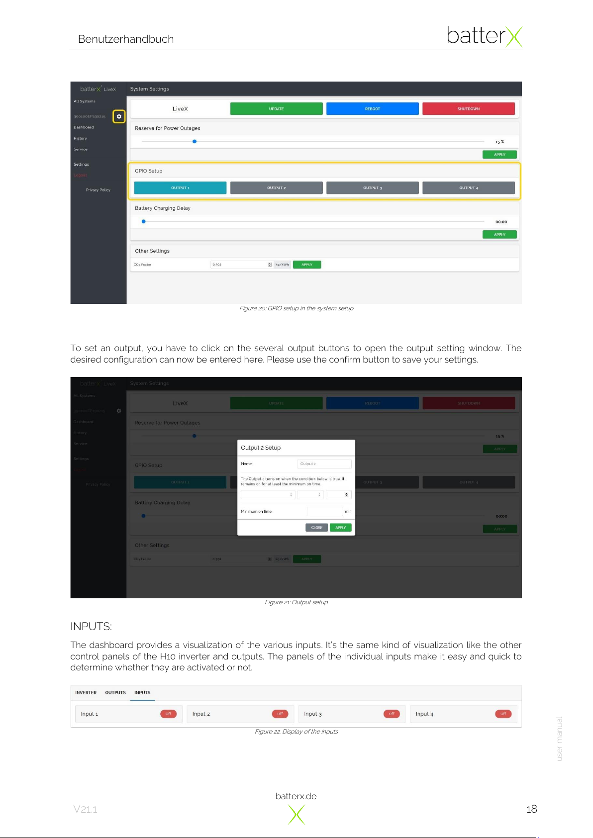
The conditions used for the automatic operation of the outputs can be found in the "GPIO setup" menu. The
GPIO settings are explained in the system settings (see also 4.IV).
batterx.de
Benutzerhandbuch
user manual
18
V21.1
Figure 20: GPIO setup in the system setup
To set an output, you have to click on the several output buttons to open the output setting window. The
desired configuration can now be entered here. Please use the confirm button to save your settings.
Figure 21: Output setup
INPUTS:
The dashboard provides a visualization of the various inputs. It’s the same kind of visualization like the other
control panels of the H10 inverter and outputs. The panels of the individual inputs make it easy and quick to
determine whether they are activated or not.
Figure 22: Display of the inputs

batterx.de
Benutzerhandbuch
user manual
19
V21.1
V. SYSTEM SETTINGS
The settings of the liveX portal are divided into two different parts:
•System settings
•General settings
As the name suggests, the system settings mainly concern the system setup. Here you can find the most
important settings. Next to the displayed serial number in the sidebar, you will find the button of the system
settings.
Figure 23: System settings
Since some parameters of the system settings have already been explained in the last points, we will only
discuss the settings that have not yet been described below.
•The main settings of the liveX hardware are located above the menu. With the buttons you can
update the liveX software and restart the liveX..
Figure 24: Main settings of the liveX
•The system is equipped with an energy monitoring system for the battery modules, which among
other things controls the energy reserve in the battery modules. The energy reserve (=emergency
power reserve) is the capacity of energy (in %) that is not intended for daily consumption, but is only
available for the customer in the event of a power failure (grid failure). The percentage setting of the
value refers to the total storage capacity. This reserve is not included in the daily consumption and is
only available in the event of a power failure.
The size of the emergency power reserve can be determined with the aid of the slider. The lowest
value is 15%, the highest 100%.
Figure 25: Slider for setting the emergency power reserve (in %)
This manual suits for next models
8
Table of contents
Other batterX Batteries Pack manuals

Popular Batteries Pack manuals by other brands


Zebronics
Zebronics ZEB MW57 user manual

A123 Systems
A123 Systems APR18650M1-A Assembly guide

Anton/Bauer
Anton/Bauer Interactive 2000 PowerCharger owner's manual

Aegis
Aegis ALF-036050A user manual

Jamara
Jamara Ride-On Strong Bull 6V Instruction

True blue power
True blue power TB40 Series Installation manual and operating instructions


