Battery Brain II Series User manual
Installation
Instructions
Instrucciones
para la instalaci6n
Instructions
d'installation
BATTERYBRAIN
/

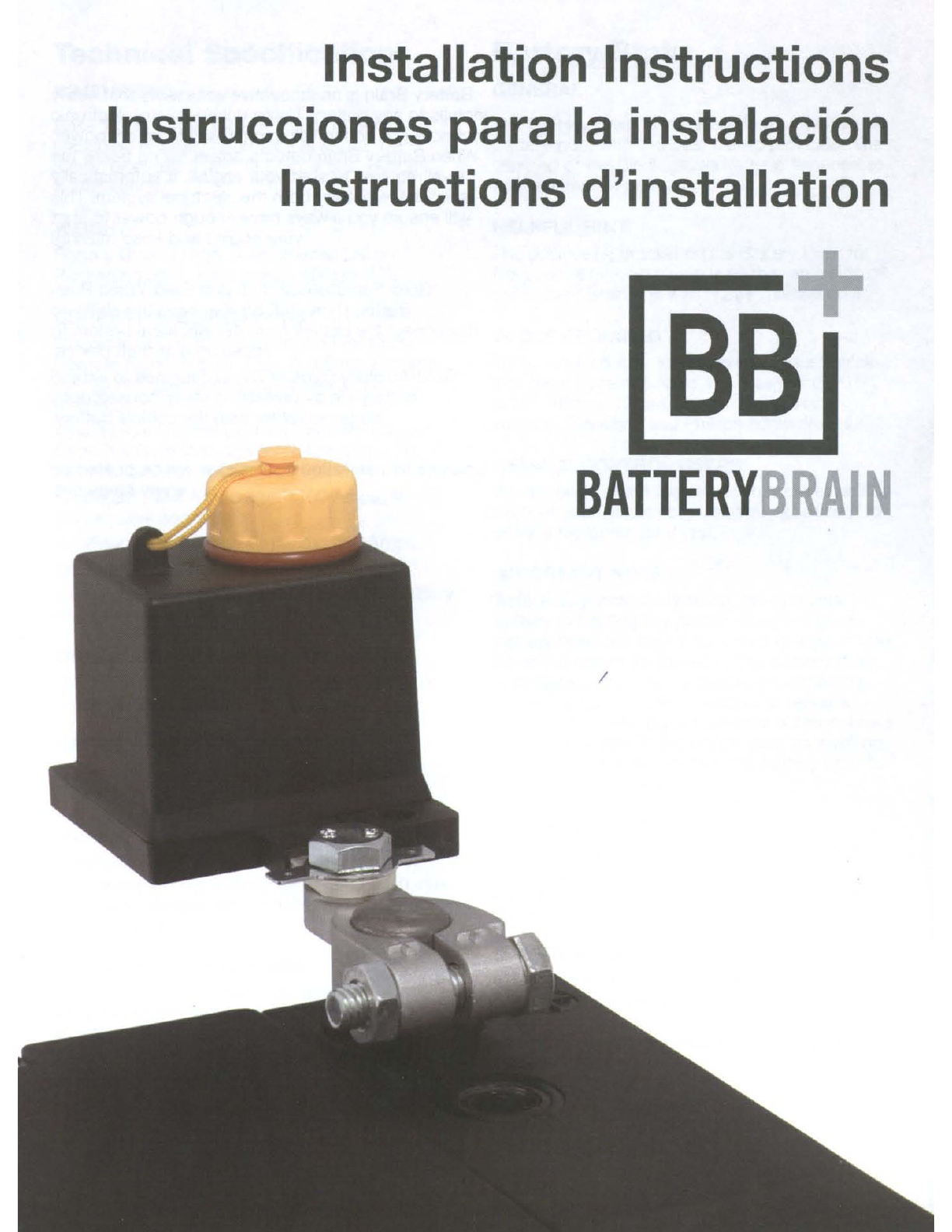
Battery Brain is
an
innovative accessory that easily
installs to any battery. Using unique micro-electronic
technology it continually monitors the battery power.
When Battery Brain detects power falling below the
level required to start your engine, it automatically
isolates the battery from the electrical system. This
will ensure you always have enough power
to
start
your engine and keep moving!
*Gold-Remote/Anti-theft and Gold-Wired Push
Button
(Type
III
&
IV)
also have the ability to
disconnect the battery from the electrical system
to
act as
an
anti-theft device.
*Gold-Auxiliary
(Type
IV
RV)
is designed to extend
battery life by protecting utility/house/coach
batteries rather than the vehicle battery.
Updates
to
installation instructions will be posted on
www.smgy.net.

Technical Specifications
DIMENSIONS
Base 1
5/8"
(4cm) x 2
1/4"
(5.5cm), Height
(including removable protective cap) 2
1/2"
(6cm), Brackets 1
1/4"
(3.5cm) x
5/8"
(1.5cm)
x
1/8"
(3mm).
WEIGHT
Battery Brain 175gm, Accessories 280gm,
Packaging 3gm; Total weight 408gm (1Ib).
CURRENT
SPECIFICATIONS
Operational Current Consumption for Silver-
Remote reconnection (Type
II)
&Gold-Remote/
Anti-theft (Type
III)
After disconnect: 3.8
Milliamps.
Operational Current Consumption for Bronze
(Type
I)
&Gold-Wired Push Button (Type
IV)
After disconnect: 0Milliamps
Maximum Peak Amperage: 1100 Amps, for 15
consecutive seconds.
Continuous Amperage Capacity: 250 Amps.
Disconnect Voltage Threshold: 11.8V
Disconnect Voltage Threshold for Gold-Auxiliary
(Type
IV
RV):
10.5V
OPERATIONAL TEMPERATURE RANGE
-60°F (-51°C)
to
200°F (90°C). Battery Brain is
made
of
non-combustible materials.
BATTERY SAFETY WARNING!
When working with lead acid batteries and
accessories, caution
must
be employed:
•Shield eyes. Do not open vent caps
or
puncture battery casing
in
any way.
•Sulfuric acid can cause blindness
and severe burns. •Rinse hands and flush eyes
with
water
immediately. •Avoid sparks, flames
and smoking.
PROPOSITION 65 WARNING
Battery posts, terminals, and related
accessories contain lead and lead compounds.
Chemicals known
to
the State
of
California
to
cause cancer and reproductive harm. Wash
hands after handling.
Battery Brain
GENERAL
The Battery Brain is installed on
the
positive
(+)
battery post with the post clamp provided. The
clip end
of
the black ground wire
is
fastened
to
the negative (-) post clamp bolt.
HELPFUL
HINT
The positive
(+)
bracket on the Battery Brain for
the positive
(+)
post clamp is on the same side
of
the Battery Brain unit with "12V+" printed on it.
TOOLS REQUIRED
Tools required may vary based on your vehicle.
The most
common
tools are; Open-end 5/16",
9/16", 1Omm, 12mm,14mm,
or
adjustable
wrench. Standard and Phillips screwdrivers.
REMOTE CONTROL USERS
Save a
copy
of
the
identification number on
the
back
of
your remote control.
You
will need it
to
order areplacement if lost.
IMPORTANT NOTE
Before beginning installation, be sure your
battery is holding the proper charge. If your
battery does not hold aminimum charge, it
may
be at the end
of
its lifecycle. The Battery Brain
is designed
to
protect aproperly functioning
or
new battery. It cannot restore
or
repair a
damaged battery. If your vehicles battery
shows
any signs
of
physical damage such as swelling,
leaking
or
cracking, replace
the
battery prior
to
installing Battery Brain.
IMPORTANT NOTE
Unless you are fully familiar with your vehicles
electrical system it is recommended
that
installation
of
this product is performed
by
a
certified technician.
IMPORTANT NOTE
This
product
is not intended
for
Marine use
and should not be submerged in water. Units
specifically designed for Marine use are
available, see www.smgy.netlbatterybrain for
more information.
Battery Brain Kit includes
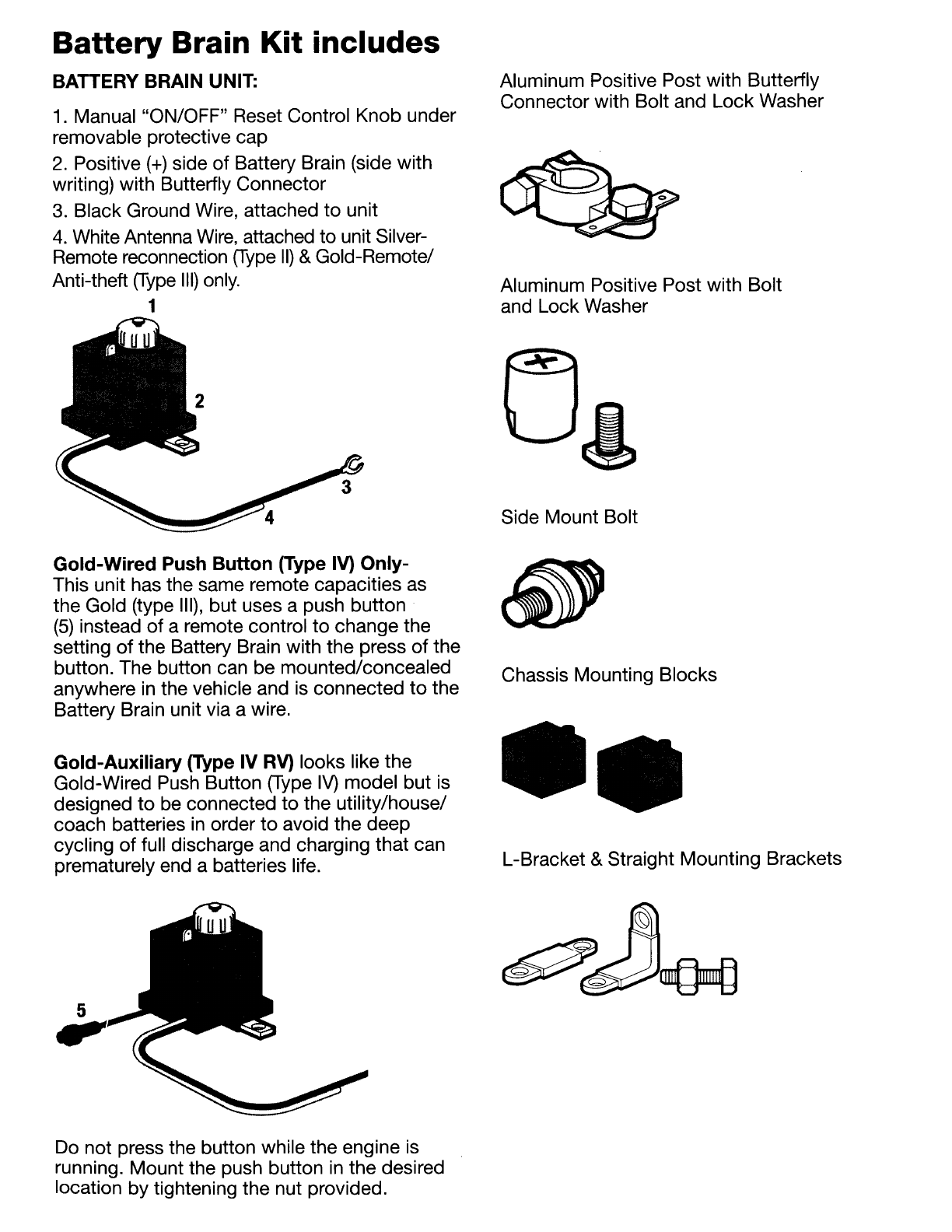
BATTERY BRAIN UNIT:
1. Manual "ON/OFF" Reset Control
Knob
under
removable protective
cap
2.
Positive
(+)
side
of
Battery Brain (side with
writing) with Butterfly Connector
3. Black Ground Wire, attached
to
unit
4.
White Antenna Wire, attached
to
unit Silver-
Remote reconnection
(Type
II)
&Gold-Remote/
Anti-theft
(Type
III)
only.
1
. U
Gold-Wired
Push
Button
(Type IV)
Only-
This unit has the same remote capacities as
the
Gold (type
III),
but
uses apush button
(5)
instead
of
aremote control
to
change the
setting
of
the Battery Brain with
the
press
of
the
button. The button can be mounted/concealed
anywhere in the vehicle and is connected
to
the
Battery Brain unit via awire.
Gold-Auxiliary
(Type IV RV) looks like
the
Gold-Wired Push Button (Type
IV)
model
but
is
designed
to
be connected
to
the utility/house/
coach batteries in order
to
avoid
the
deep
cycling
of
full discharge and charging
that
can
prematurely end abatteries life.
Do not press the button while the engine is
running.
Mount
the push button
in
the
desired
location
by
tightening
the
nut provided.
Aluminum Positive Post with Butterfly
Connector with Bolt and
Lock
Washer
Aluminum Positive Post with
Bolt
and
Lock
Washer
Side Mount Bolt
Chassis Mounting Blocks
••
L-Bracket &Straight Mounting Brackets

Installation Instructions
Remote Control Silver-Remote reconnection
(Type
II)
&Gold-Remote/Anti-theft
(Type
III)
Models Only)
Remote Control Frequency: TX433.92 Mhz
Battery Type: 12 V
27
A
(The
batteries are
already installed)
NOTE: Battery location and position differ
in
vehicles. With the supplied accessories you can
mount the Battery Brain on the vehicle using
the Top Mount, Side Mount
or
Chassis Mount
positions.
NOTE: After installation ensure
all
connections
are tight. Ensure manual reset control
knob under the protective cap is
in
the on
position. Press down on the knob to establish
connection.
Sample Configuration Options
Top Mounting Options
Red Accessory Bypass Wire with Fuse Holder
Black Engine On Wire
Side Mounting Options
+
Chassis Mounting Option
Optional:
Vibration Sensor -Available separately, can be
used in place
of
the Engine
On
Wire
*(See your retailer for details)

STEP
1:
Disconnecting Battery Cables:
A)
Disconnect the black/negative (-) cable from
the negative (-) battery post/bolt on the battery.
B)
Disconnect the red/positive
(+)
cable from the
positive
(+)
battery post/bolt on the battery
D)
Side mount only: Connect the positive side
of the Battery Brain (with the sign 12V
+)
to the
positive post on the battery using the provided
side mount screw. Then connect the
red
positive battery cable to the other side of the
Battery Brain.
STEP
2:
Connecting the Battery Brain:
A)
Unscrew removable protective cap
on
the
top
off the unit and turn the "ON/OFF" manual reset
control knob to the "ON" position.
OFF
C=
0::::::==----.
ON
OFF
B)
Connect the Aluminum Positive Clamp with
butterfly connector
to
the Positvie side (the side
with 12V+ printed) of the battery brain. Then
connect the Aluminum Positive Clamp to the
positive terminal on the battery.
C)
Connect the male post to the other side of
the Battery
Brain.
Connect the
red
positive battery
cable to the male post.
NOTE: The positive battery post
is
tapered.
Verify that the cable is mounted correctly.
STEP
3:
Connecting Battery Brain to Ground:
A)
Connect the black/negative (-) battery cable
to the negative (-) post/bolt
on
the battery.
B)
Connect the clip end
of
the black ground
wire to the clamp bolt on the negative (-)
battery post/nut or ground to chassis with a
metal screw.
CHASSIS MOUNTING
A)
Connect the positive
(+)
side of the Battery
Brain to the positive
(+)
side of the battery with
aseparate red positive battery cable (must be
purchased).
B)
Connect the original red positive
(+)
cable of
the car to other side
of
the Battery Brain.
C)
Connect the black ground wire
of
the Battery
Brain to the chassis or directly to the negative
post of the battery.

STEP
4: Install
Black
Engine On Wire
Installation
of
the Engine
On
wire will prevent
the Battery Brain from disconnecting the battery
while the engine
is
running. This will also
prevent the Battery Brain from disconnecting
the battery if the voltage level drops below
11
.8V as could be the case with accessories
that briefly reduce the voltage below the
threshold level or
in
the case of problems with
the vehicle electrical components. i.e.: bad
alternator.
This wire must be installed to ensure the
Battery Brain will not activate while the engine
is running.
*Not required if optional Vibration Sensor is
used. (Purchased separately).
A)
Locate awire or fuse that has 12V when the
ignition switch is
in
the "ON" or "RUN" position
and is
OV
when the ignition switch
is
in
the
"OFF" position.
B)
Slide the connector end
of
the black engine
on wire onto the single connector
on
the
Battery Brain that
is
labeled with "ACC".
C)
Attach the other end
of
the supplied black
engine on wire to the selected wire or fuse
as located
in
step Aabove. This may require
running awire
to
the interior of the vehicle.
Afuse-tap or wire-tap connection may be
required.
STEP
5:
Red Accessory Bypass Wire
Installation [Optional]
Installation
of
the red accessory bypass wire
will provide you with continuous 12V power
to
an
accessory or accessories bypassing the
Battery Brain designed to allow you
to
save
presets or memory settings.
NOTE: Use
of
this feature will bypass the
Battery Brain and may allow the battery voltage
to drop below the minimum charge needed
to
start your vehicle.
NOTE: Exact location ofthe fuse &fuse panel
will differ by manufacturer; consult your owner's
manual or wiring schematic forthe vehicle
to
locate fuses for the accessories. Amperage for the
bypassed accessory must not exceed 7.5Amps.
A)
Locate the fuse that provides power only to
the accessory that you wish to have it active at
all
times.
B)
Attach the exposed end of the red bypass
wire
to
the fuse or device you wish
to
have
active on the non active side of the fuse. Afuse
tap connection may be required.
C)
Carefully route the wire from the fuse
to
the
Battery Brain. Afuse-tap or wire-tap connection
may be required.
D)
Attach the connector end of the red bypass
wire onto the butterfly connector on the female
positive post of the Battery Brain.
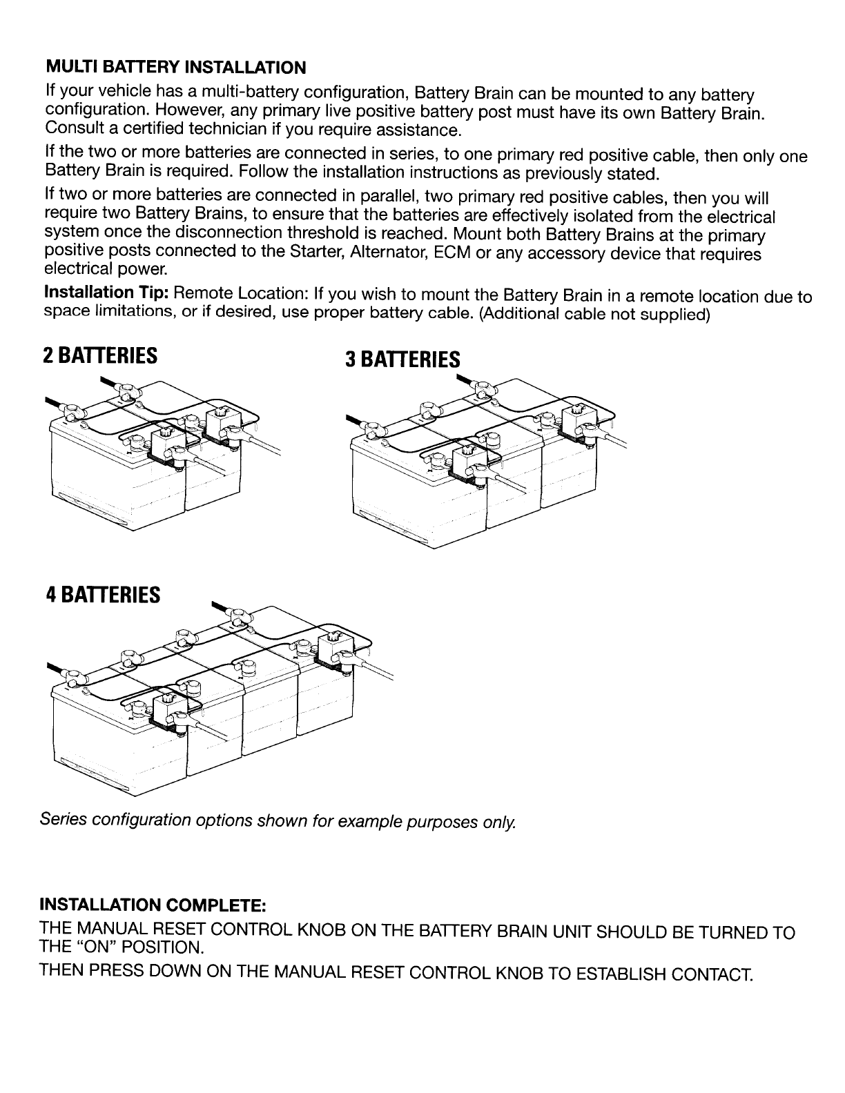
MULTI BATTERY INSTALLATION
If your vehicle has amUlti-battery configuration, Battery Brain can be mounted
to
any battery
configuration. However, any primary live positive battery post must have its own Battery Brain.
Consult acertified technician if you require assistance.
If the
two
or more batteries are connected
in
series,
to
one primary red positive cable, then only one
Battery Brain
is
required. Follow the installation instructions as previously stated.
If
two
or more batteries are connected
in
parallel,
two
primary red positive cables, then you will
require
two
Battery Brains,
to
ensure that the batteries are effectively isolated from the electrical
system once the disconnection threshold is reached. Mount both Battery Brains at the primary
positive posts connected
to
the Starter, Alternator,
ECM
or any accessory device that requires
electrical power.
Installation Tip: Remote Location: If you wish to mount the Battery Brain
in
aremote location due to
space limitations,
or
if
desired, use proper battery cable. (Additional cable not supplied)
2
BATTERIES
4
BATTERIES
3
BATTERIES
Series configuration options shown for example purposes
only.
INSTALLATION
COMPLETE:
THE MANUAL
RESET
CONTROL KNOB ON THE BATIERY BRAIN UNIT SHOULD
BE
TURNED TO
THE "ON" POSITION.
THEN PRESS DOWN
ON
THE MANUAL RESET CONTROL KNOB
TO
ESTABLISH CONTACT.
Testing
the
Installation
A)
TO TEST FOR SUCCESSFUL
INSTALLATION:
Start the engine after installation is complete. If
the engine starts properly proceed
to
the next
step. If not, review the installation instruction or
consult acertified technician.
B)
TO
TEST BATTERY BRAIN OPERATION:
With the Manual Reset Control Knob
in
the
"ON" position turn the engine off and turn
on as many electrical accessories
(i.e.
lights,
radio,) as possible and leave them on. The
Battery Brain will cut power from the battery
automatically -confirming the Battery Brain
is
working. This may take some time, depending
on the battery's age and state of charge.
C)
TO
TEST THE MANUAL RESET CONTROL
FUNCTION:
Ensure that the Manual Reset Control Knob
is
in
the "ON" position and press it down after the
Battery Brain has disconnected the power (to
reset). The unit should reestablish power to the
electrical accessories and enable you to start
the engine.
D) TO TEST THE REMOTE CONTROL
UNIT
IWIRED REMOTE BUTTON UNIT (BATTERY
BRAIN GOLD-REMOTE!ANTI-THEFT &
GOLD-WIRED PUSH BUTTON):
The remote control unit supplied with Battery
Brain Gold-Remote/Anti-theft
(Type
III)
and the
wired remote button supplied with the Battery
Brain Gold-Wired Push Button
(Type
IV)
can
be used
to
disconnect and reconnect power
by choice
(as
an
anti-theft deVice), as well
as reestablishing power after draining. Press
and hold for 4consecutive seconds either the
remote control button or mounted switch
to
disconnect, reconnect or reestablish power
to
electrical accessories and
to
start the engine.
If
problems
occur
with any
of
the test
procedures, please refer to Trouble Shooting
Instructions
or
consult Battery Brain technical
support.

Trouble Shooting
AFTER INSTALLATION, THE BATTERY BRAIN
DOESN'T SEEM TO BE WORKING.
WHAT
TO
DO:
1.
Be sure your battery is holding the proper
charge.
2.
Make sure the positive side
of
the Battery
Brain (the side with the writing)
is
attached
to
the positive
(+)
post
of
the battery.
3.
Check that the Manual Reset Control Knob
is
pointing
to
the "ON" position.
4.
Check that the black ground wire is securely
attached to the negative
(-)
post on the battery.
AFTER THE BATTERY BRAIN HAS
DISCONNECTED POWER, THE REMOTE
CONTROL DOES NOT RESET
THE
POWER.
WHAT
TO
DO
1.
Make sure that the light on the Remote
Control
is
lit when you press the button down.
If the light does not come on, open the Remote
Control and replace the battery.
2.
Hold the Remote Control button down for
five seconds to activate Battery Brain.
3.
Turn
the Manual Reset Control Knob
to
"ON".
4. Check that the black ground wire is securely
attached
to
the negative
(-)
post on the battery.
BATTERY BRAIN IS FREQUENTLY
DISCONNECTING POWER FOR
NO
APPARENT REASON.
WHAT
TO
DO
1.
Your car battery may be low
in
power due to
Alternator function. If it cannot hold acharge, it
may be at the end
of
its life cycle.
2. The electrical system might have an unknown
short. Consult acertified technician.
3.
Make sure all lights are off.
4.
Disconnect all accessory electronics (radio,
phone charger,
DVD
player, etc.) and check
again.
YOU CANNOT DETERMINE ABATTERY
BRAIN INSTALLATION CONFIGURATION
FOR YOUR VEHICLE OR LOCATE BATTERY
CONNECTIONS.
WHAT
TO
DO
1.
Consult acertified technician.
IMPORTANT NOTE:
If awarning light for NO CHARGE or BAITERY
WARNING illuminates on your dashboard, stop
your vehicle at asafe area and TURN THE
MANUAL
RESET
CONTROL KNOB (located
under the removable protective cover on
the Battery Brain unit itself) TO THE "OFF"
POSITION. Your vehicle will experience a
complete loss
of
power unless the "No Charge"
problem is repaired immediately! This problem
is unrelated
to
the Battery Brain and requires
assistance from aqualified technician.

Limited Warranty
Your Battery Brain™
is
covered by aconditional,
limited warranty to the original purchaser.
This unit is guaranteed
to
the original retail
purchaser against defects
in
quality
or
workmanship
for
aperiod
of
two
years from the date
of
original purchase. If this unit fails because
of
a
manufacturing defect within 30 days
of
purchase,
return the unit, with your receipt,
to
the retailer. After
30
days
of
purchase, but within the warranty period,
if the unit was purchased within the continental
United States, return it, freight prepaid,
to
Smart
Energy Solutions, Inc. for repair
or
replacement.
If the unit was purchased outside the continental
United States, return the unit
to
the place
of
purchase.
This warranty does
not
cover damage due
to
operation other than the use
of
the correct Battery
Brain model on the specified battery voltage.
This warranty
does
not extend
to
any defect,
malfunction,
or
failure caused by accidents, misuse,
abuse, improper installation (including disassembly
of
Battery Brain, use
of
the product with equipment
for
which it was not intended,
or
unauthorized
alterations
or
repairs.
All implied warranties are hereby limited
in
duration
to
the period
of
two
years from the date
of
original
retail purchase. Incidental
or
consequential damages
arising from abreach
of
either express
or
implied
warranties are hereby disclaimed and excluded.
Some states
do
not allow the exclusion
of
limitation
of
incidental
or
consequential damages, so this
limitation or exclusion may not apply
to
you.
Neither Smart Energy Solutions, Inc. nor retailers
selling Battery Brain are responsible for indirect,
incidental, special, punitive or consequential
damages arising from improper installation, the use
of
or
inability
to
use Battery Brain. Except for this
limited warranty, Smart Energy Solutions, Inc. has
not
made, and specifically disclaims any warranty
or
representation
of
any kind, express
or
implied, direct
or
indirect,
of
product fitness for aparticular purpose.
Assembledin China for Smart Energy Solutions, Inc.
This manual suits for next models
3
Table of contents
Popular Automobile Accessories manuals by other brands


Echomaster
Echomaster MRC-HDDVR user manual

Mazda
Mazda TD11 V3 460F Installation and user instructions

Firefly
Firefly ISATA manual

Hamron
Hamron 326-052 User instructions

Star Headlight & Lantern
Star Headlight & Lantern Mini Phantom ULB9 Installation and instruction manual

Metra Electronics
Metra Electronics 99-4644 installation instructions