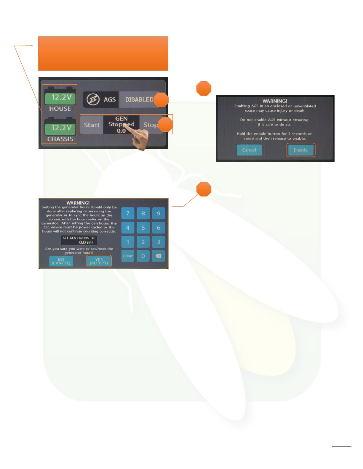
Firefly ISATA User manual

1
Dynamax Isata 3 - V1 OEM Manual

2
Dynamax Isata 3 - V1 OEM Manual
The information contained in this manual is a general overview of the Firefly
system and is subject to change at any time.
2Table of Contents
3 Lyra Screen Overview
4 Home
7 Auto Gen Start (AGS)
8 Lights
9 Climate Control
10 Slides
11 Settings
13 Settings/Mobile App
14 Vegatouch Mira Setup
18 Wireless Switch Pairing
19 Settings/Network Diagnostics
20 Settings/Display Colors
21 Floorplan and Options
22 SSP17 Switch Panels
23 G12 DC Panel
24 Networking
26 System Diagrams

3
Tap any icon from the navigation menu to select your desired page. The currently selected page will
always be listed in the top corner of the screen.
Navigation Menu
Lyra Screen Overview
Home
AGS
Slides
Lights
Climate
Settings

4
Buttons will turn Blue while a circuit is on and Grey once the circuit has been turned off. This color
change is known as showing status.
Tap to toggle the Water Pump On/Off.
Tap to toggle the Inverter On/Off.
Light Master controls all interior lights at once. When Light Master Off is pressed, it will remember
which lights were on. Then, when Light Master On is pressed, it will only turn on the lights that are in
memory. To turn on all lights again, press and hold Light Master On for at least one second.
*Troubleshooting –Memory is rewritten each time Light Master Off is pressed. In the case that it is
pressed twice in a row, it will remember that no lights were on and just touching Light Master On won’t
turn on any lights. Press and hold Light Master On to turn the lights back on. Note: Light Master On/Off
buttons will always appear red and will not show feedback at any time.
1
Home
1
2
3
3
2
Current Temp with Currently active
climate mode graphic/fan speed.
Tap the arrows to select your desired
temperature (Set Temp).

5
LP Tank Readings:
•Below 25% will read “Low” and the
tank level will show as normal.
•From 25% to 75%, the tank level and
percentage will show as normal.
•From 75% to 96%, will read “Full” and
the tank level will show as normal.
•97% and above will read “Disc.” and
the tank level will be empty.
Water Tank Readings:
•Below 10% will read “Empty” and the
tank level will show Empty.
•From 11% to 89%, the tank level and
percentage will show as normal.
•90% and above will read “FULL.” and
the tank shows accurate level.
Tap to toggle the
Tank Heaters On/Off.
Individual tank graphics represent the
percentage filled for holding tanks
(Currently disconnected).
Propane % remaining (Currently
disconnected).

6
Generator Controls
The Generator display will show the total
number of generator hours accumulated
as well as the current operating status
(running or stopped). Generator hours
are saved to the system, not to the
generator itself. Press and Hold the hours
display for 3 seconds to enter the Set Gen
Hours screen. Type in the required gen
hours and tap Yes to accept and exit.
Power Cycle the coach to ensure that your
preference has saved.
Gen Start –Ensure that the red button on
the generator remote is depressed before
continuing.
Press and Hold to start the generator.
Please note that the generator requires a
press and hold because it operates on a
one-second delay as a safety feature to
help prevent accidental generator starts.
Gen Stop –Press and hold to stop the
generator.
House/Chassis DC Voltage Display Graphics.
These graphics will turn red when the voltage
drops below 12v.
4
5
5
AGS
Tap to Enable/Disable AGS (Action Required).
4

7
Tap to Enable/Disable AGS. A warning message will require action to Enable.
Trigger Options –Automatically start the generator using specified voltage settings
(Low Volts) or when A/C or Heat Pump starts (HVAC). Select one or both triggers.
If no triggers are selected, AGS will not run. Disable HVAC Load while connected to
shore power to keep the generator from starting.
Auto Gen Start (AGS)
Quiet Time Start - Use the +/- buttons to select the starting point for Quiet Time, the
hours that your generator will not run in an effort to reduce noise.
Start at Volts - The generator will start when the voltage drops to this set point
depending on “Time at Start Volts” setting below. (Range 10.5v – 12.5v)
Time at Start Volts - The generator will start when the voltage drops to the Start at
Voltage for this specific amount of time. (Range 5 seconds –1 minute) 5 seconds –1
minute)
Stop at Volts - The generator will shut off when the voltage reaches this set point
depending on “Time at Stop Volts” setting below. (Range 13.2v – 14.5v)
Time at Stop Volts - The amount of time required for the voltage to remain at “Stop at
Volts” level before the generator shuts off. (Range 5min –120min)0min
Minimum Gen Run Time - Use the +/- buttons to set the minimum amount of time that
your generator will run once it has started. (Range 10min –30min)0min –30min)
Maximum Gen Run Time - Use the +/- buttons to set the maximum amount of time that
your generator will run once it has started. (Range 120min –720min)
(Range 120min –240min)
–30min)
Gen Start Retries - Use the +/- buttons to set the number of tries that your generator
will retry to start. (Range 1-5 retries)
–30min)
Quiet Time Stop - Use the +/- buttons to select the stopping point for Quiet Time. AGS
will work normally at this point.
Gen Hours Display - The number of hours that the generator has been used. These
hours are saved to the system, not the generator itself.

8
This screen will control the lighting for the entire coach, including the exterior. Tap any button to turn
the desired light On/Off.
Lights with up/down arrows are dimmable. Press and hold these buttons to ramp the brightness up or
down. Tap the buttons to toggle On/Off.
Lights

9
Cool –Tap to operate the air conditioning. The A/C will run until the current temp reaches your desired
temp and then shut off. The Climate Mode graphic will only display when the compressor is running.
Heat Pump –Tap to operate the Heat Pump. The Heat Pump will run until the current temp reaches
your desired temp and then shut off. The Heat Wave graphic will only display when the HP is running.
Furnace –Tap to operate the Furnace. The Furnace will run until the current temp reaches your desired
temp and then shut off. The Furnace can be used in conjunction with the Heat Pump and the button will
stay engaged until the user taps it off. The Flame graphic will only display when the Furnace is running.
Auto –Tap to enable Auto Mode. In this mode, either A/C or Heat Pump will automatically run to keep
your desired temperature consistent. Fan speeds will be adjusted automatically.
Fan speeds –Fan only mode is available when no other climate mode has been selected. The fan will
operate by choosing High or Low. Auto will not only turn off the fan, but also control fan speeds to get
the system to the required temp the best way possible.
Climate Control
Use the Arrows to select your
desired temperature by zone.
Current zone temperature,
Climate mode graphic and Fan
Speed indicator (H or L).
1
1
2
2
3
4
5
3
4
5

10
The Extend buttons will be locked out until the parking brake has been applied.
Press and Hold EXT or RET to operate the Slides and Awnings.
Slides

11
Tap to navigate to the Network Diagnostics page.
Please note the GUI and Logic Controller Versions and have these numbers available before contacting Tech Support.
Tap the disable the touchscreen for 15 seconds for the purpose of cleaning.
Floorplan display.
Wireless switch status display.
Tap to select between Fahrenheit and Celsius.
Tap to navigate to the Vegatouch Mira connection screen.
Settings
1
2
3
4
1
2
3
4
5
6
6
5

12
Tap the buttons to set the time or select 24-hour time mode.
When Auto Dimming is enabled, the screen will enter sleep mode after 60 seconds of inactivity. Tap anywhere
on the screen to wake it up. Please note that even if Auto Dimming has been disabled, the screen will still enter
sleep mode after 4 hours of inactivity during daytime hours (5am –10:59pm) and after 15 minutes of inactivity
during night time hours (11pm-4:59am) as the result of a built in screen saver that cannot be disabled.
Tap to visit the Display Colors page to customize the look of your touchscreen.
Tap the buttons to select between 10 levels of screen brightness and off.
7
9
8
10
7
8
9
10

13
Vegatouch Mira is a wireless control module that easily connects to any Android or iOS device
to give total control to many electrical, electronic and mechanical systems in your coach. Pair
any device with the coach’s built-in interface to monitor and control many coach components.
Settings/Mobile App

14
Notice: Make sure that Bluetooth is turned ON in your smart device
settings before proceeding.
Locate the Login Information:
The login informationcan be
found by clicking on the Mobile
App button on the settings page
of the touchscreen or from the
Mira module’s label.
Download:
Download Vegatouch Mira from the Google Play store or the App Store. Once the download
has finished, install the app and open it.
Setup:
Tap SCAN to find the Mira Module’s signal. After scanning, any Mira Module in your area will
appear on the screen. Tap the ID # that matches the one on your Mira label. Enter the PIN
number from the Mira label and press AUTHENTICATE to connect to the system.
Vegatouch Mira Setup

15
Notice: iOS Setup Tips
Turn on Bluetooth to allow Vegatouch Mira to
connect to Accessories.
If you do not have Bluetooth turned ON in your iOS settings
you will see this screen. Do not click OK, you must click
SETTINGS. Your Bluetooth Settings page will now appear and
you should turn Bluetooth ON.
Notice: Android Setup Tips
Allow Vegatouch Mira to access this device’s location.
Mira will need to be allowed access to your location. Click ALLOW when you see this
screen.

16
App Settings:
Access the App Settings page by tapping the triangle (at the bottom of the screen) to expose the
Settings button. Tap the gear to visit the settings page.
Tap to Temperature Units selection to
choose between Fahrenheit and Celsius.
System Information and Mira Name.
Tap to disconnect your device from Mira.
Tapping Update Config will force a
download of the config from the cloud.
Tap to enter the Diagnostic Tools screen.

17
Diagnostic Tools:
Tap to display a list of currently
connected devices.
Remote Help is available by calling Firefly
Integrations. Do not enable remote help
without consultation.

18
The switch Battery Graphic will identify the status of the wireless switch panel.
Green battery switch indicator –the switch is currently conencted to the screen.
Red battery switch indicator - The switch is currently disconnected from the screen. It is likely that the
battery inside your switch panel needs replaced. The wireless switch panel in your coach will illuminate
a green LED whenever a button is pressed. If the LED on your switch panel does not illuminate when
you press a button on your switch, you will need to replace the 2032 coin cell battery.
If a new battery will not fix the issue, you might need to pair the switch panel to the screen.
Press and Hold your desired switch graphic for 3 seconds until the pairing screen appears.
Tap Start Pairing. You’ll have 30 seconds to press any 2 buttons on the switch panel at the same time.
Tap Done once the pairing successful message appears. It may take up to 10 minutes for the wireless
switch indicator to turn Green, but the switch should work instantly once paired.
Wireless Switch Pairing
1
2
3
1
2
3
30

19
This screen will show the status of the Lyra screen and the G12. It will also display any current faults the
system is experiencing.
Settings/Network Diagnostics

20
Tap a preset color scheme below to change the color of your touchscreen. Tap apply to save and exit.
Settings/Display Colors
This manual suits for next models
1
Table of contents
Other Firefly Automobile Accessories manuals
Popular Automobile Accessories manuals by other brands

Westin
Westin 21-2310 instructions

Gamber Johnson
Gamber Johnson 7160-0348 installation instructions

Thule
Thule Rapid System 1183 Fitting instructions

SportRack
SportRack EXPLORER A90095 instruction sheet

Tritium
Tritium RTM75 operating manual

Snapper
Snapper Front Implement Lift Kit 1691195 installation instructions