Acdeos AXS - FL Step User manual

Manual
ACDEOS BV
Touwbaan 1A
2352 CZ Leiderdorp
Netherlands
WWW.ACDEOS.COM
Date: April 2020
Vers: 3.0
AXS –FL Step

AXS –FL Step Manual
AXS –STEP Manual vers 3.0
2
Index
1Environment .................................................................................................................... 2
2Technical specifications............................................................................................... 3
3Safety instructions......................................................................................................... 3
4Constraints....................................................................................................................... 4
5Controls ............................................................................................................................ 4
5.1 Step Control .......................................................................................................................................... 4
5.2 Signals ................................................................................................................................................... 4
5.3 Legal requirement according R 107 UN Bus directive: .................................................................. 4
5.4 Electrical Components ........................................................................................................................ 4
5.5 Power..................................................................................................................................................... 4
5.6 Current control...................................................................................................................................... 4
5.7 Motor ...................................................................................................................................................... 4
6Operation.......................................................................................................................... 5
6.1 Deploy Operation procedure .............................................................................................................. 5
6.2 Stow operation procedure................................................................................................................... 5
7Manual Operation ........................................................................................................... 6
8Mounting / Installation ..................................................................................................6
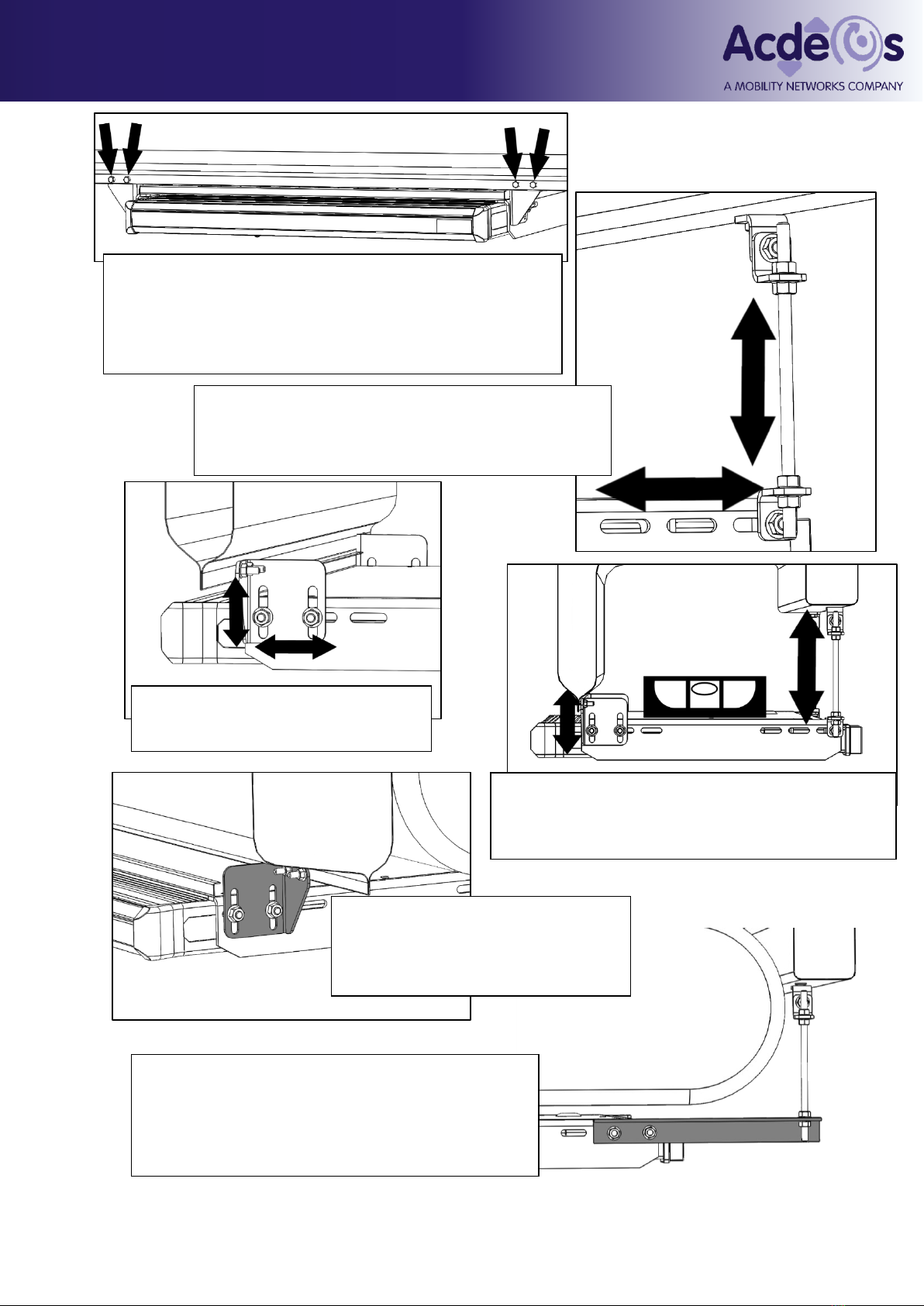
8.1 Mechanical Installation ........................................................................................................................ 6
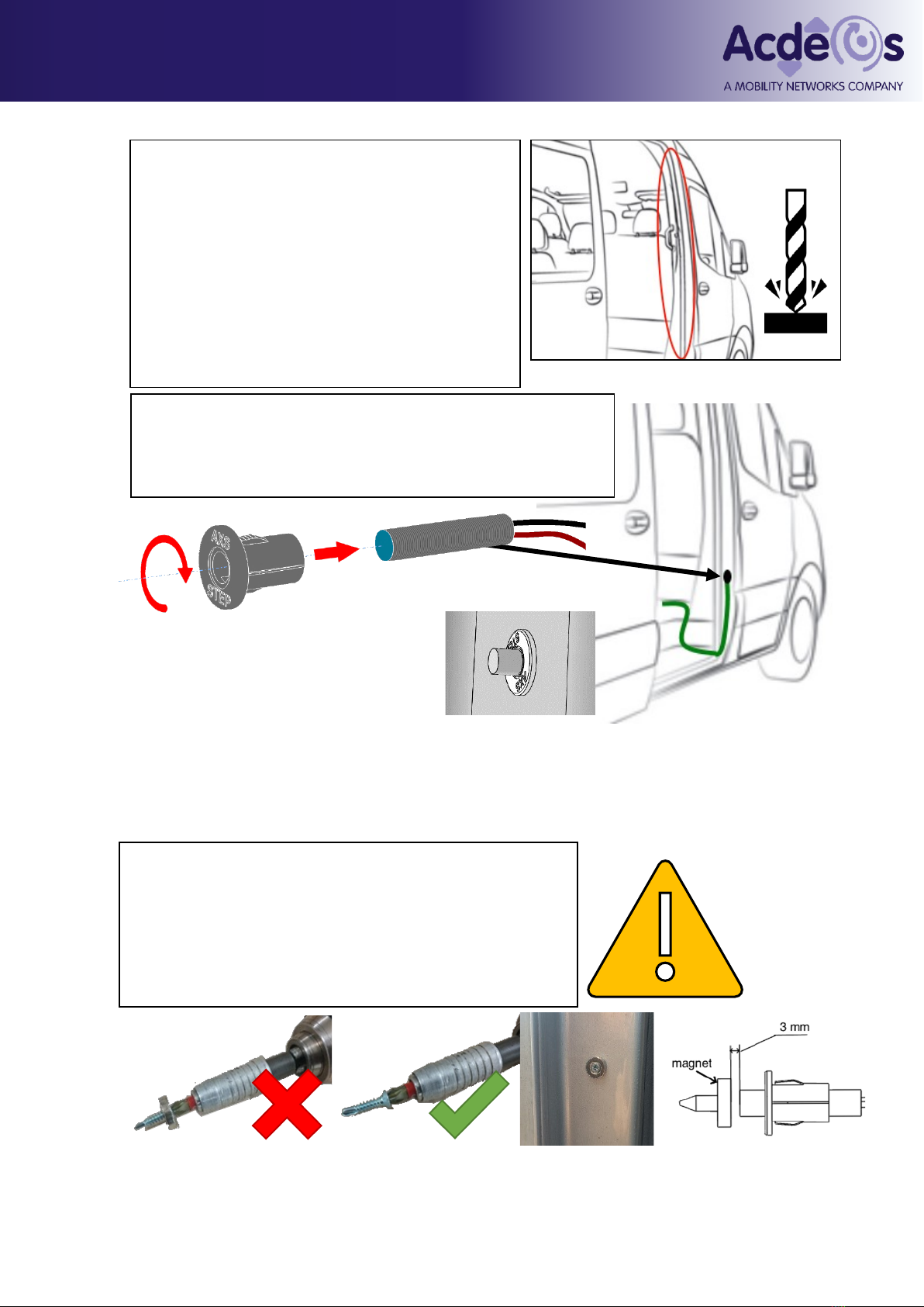
8.2 Electrical Installation ............................................................................................................................ 8
8.3 Installation of the LED (optional):..................................................................................................... 11
8.4 Testing the Step: ................................................................................................................................ 13
9Periodic maintenance / Inspection .......................................................................... 13
9.1 Cleaning .............................................................................................................................................. 13
9.2 Periodic maintenance / Inspection................................................................................................... 13
9.2.1 Small maintenance .................................................................................................................... 13
9.2.2 Regular inspection ..................................................................................................................... 13
9.2.3 Yearly maintenance / normal maintenance............................................................................ 13
10 Repair ........................................................................................................................... 14
10.1 Disassembly.................................................................................................................................... 14
10.2 Assembly......................................................................................................................................... 16
11 Failure search ............................................................................................................ 20
12 Certification ................................................................................................................ 21
13 Spare parts..................................................................................................................22
Appendix 1;........................................................................................................................... 26
Appendix 1 a; ....................................................................................................................... 27
Appendix 2;........................................................................................................................... 28
Installation drawings: ........................................................................................................ 28
1Environment
The use of energy from the step is reduced to an absolute minimum.
The AXS - Step is made of durable materials which all can be recycled. All different materials can easily
be separated from each other for separate recycling.

AXS –FL Step Manual
AXS –STEP Manual vers 3.0
3
2Technical specifications
Product description Electric operated step for mounting outside under the floor of a vehicle.
Installation Under the vehicle Floor at the front- middle or rear door
Dimensions Step depth 300 mm - width depending on model 600, 900 or 1000mm
For detailed dimensions please refer to the installation drawings
Weight total 24-28 Kg depending at model.
Load Maximum load 200 Kg (2000 N) this is always labeled on the Step.
Materials Frame; steel plate work, EP corrosion protected.
Step: Aluminum profile plastic front edge and Plastic corner pieces.
Life cycle Tested life cycle of the step is 100.000 cycles.
Electrical connection Waterproof 4 pin connector (IP65) on the step.
Power consumption max average 4 Amp short peak up to 15Amp, sleep current < 5mA
Drive Electric motor 12V 20W (or optional 24V at special demand)
Electric signals following electric signals are available: Step closed / stowed.
Safety functions Motor switched off by current control.
Cycle time Time required for opening or closing the step is approx 2,5 Sec
Legislation The product fulfils R 107 UN Bus directive and 2006/42/EC / 98/37 EC Machine
directive.
3Safety instructions
These Safety instructions should always be with the step. The operator must be
made aware of these instructions before operating the Step. Read these safety
instructions carefully and follow them.
The step is constructed to be an extra step to enter a vehicle. It should be used appropriately by
passengers as long as they are not heavier as the maximum load, to enter or exit a minibus, taxi,
camper or other vehicle.
1. Before you can operate the step you have to stop the Vehicle and make sure that the
hand or park brake is on.
2. Before you operate the step, make sure that there is no person or obstacle at or close to
the step. Look out that there is no person or obstacle outside the vehicle in the motion
direction of the step.
3. It is recommended that the step is only operated by the driver or other qualified
operators.
4. The driver or operator must have a clear view at the step when he is operating the step.
5. It is recommended to step on the middle of the step platform.
6. NEVER drive away when the RED dashboard LED light is still on. The step is not properly
stowed.
7. The step platform must be kept clean and free of oil and other slippery materials.
8. When you have any doubt about the safety of passenger when using the step make sure
he is assisted.
9. For any questions about the safe operation of the step, directly contact the responsible
persons.
10. Never use the step for any other use than here described.
11. Never overload the step.
12. The step should always be operated until it is fully in or out.
13. Repair and maintenance must be done by qualified and trained staff only.
14. Only use original parts if you have to exchange parts from the step.
15. If the anti-slip profile at the step becomes slippery because of wear, the step platform
must be replaced.
16. Always use the recommended cleaning materials.
17. Report any unsafe condition of the step, or during it’s operation, to the step supplier.

AXS –FL Step Manual
AXS –STEP Manual vers 3.0
4
4Constraints
The step has been designed to be functional and reliable. The product is made as simple and reliable
as possible. It has been taken in consideration that the step will be mounted under a vehicle in severe
environmental conditions
5Controls
5.1 Step Control
The step control is made as easy as possible. The controls comply with European 98/37 EC machine
directives. Functions and measurements are compliant with the R 107 UN Bus directive.
The electric step is an automatic system controlled by opening and closing of the vehicle door or
optionally by a driver operated switch.
5.2 Signals
The following output signals are available from the step electronics:
•Step out.
This is a red LED to make clear to the driver that the step is not in the stowed position and that he
cannot drive away safely. This signal will blink when the step is moving in or out
•Step in operation, moving in or out.
There is an audible signal when the step is moving in or out.
5.3 Legal requirement according R 107 UN Bus directive:
•Driver must have an indication that the step is fully stowed. It should be impossible to deploy the
step when a safety device fails. Manual operation is allowed.
•The horizontal movement of a step shall be interrupted when it is loaded with a mass of 15 kg.
•Extension of the step in the horizontal direction shall be protected by a safety device. In the event
of a safety devices coming into operation, the movement of the step shall immediately be stopped.
The Step On fulfils all these requirements.
5.4 Electrical Components
All electrical components in or outside the step cassette are water resistant to IP 65.
5.5 Power
12-volt commercial vehicle electrical system. Such a system consists of a 12-volt battery and an
alternator/generator system. The step performs all necessary functions when subjected to the normal
fluctuations encountered in a normally functioning 12V DC, commercial vehicle electrical system.
(optional 24 V system)
IMPORTANT Note: The ECU is not protected against changing the polarity at the power lead.
This will damage the ECU.
The power line needs to be protected by a 20 Amp fuse. This fuse is not included in the cable
loom.
5.6 Current control
The Step has a current control function. The step will stop with a load of max 150 N in front of the step.
It will retract and then try again to continue its movement out. It will try three times to move out, then it
will stay in the position where it was obstructed and fully returns when the door is closed or the driver
closes the step by a driver operated switch.
5.7 Motor
The motor specifications:
Voltage 12V DC (or 24V optional)
Unloaded rotation speed 70 rpm
Unloaded current 2 A
Rated load 350 Ncm
Rated current 5-6 A
Locked torque 850 Ncm
Start / lock current 18 A
Current cut of by ECU 6,5 –7.5 Amp

AXS –FL Step Manual
AXS –STEP Manual vers 3.0
5
6Operation
6.1 Deploy Operation procedure
The step must have clearance from the vehicle. The vehicle
must have the parking brake on, and then the step can be
safely operated.
The electronics receive a signal from the door switch or driver
switch. If a door switch is installed the step will move out
automatically once the door is opened.
Time for either the full deploy / out or the full stow / in cycle is
approximately 2.5 seconds. When the step is moving the red
LED on the dashboard will flash until the step is completely out.
If the step encounters an obstacle it automatically stops. It will move backwards for a few centimeters
and then move forward again. If there is still an obstacle it will repeat this procedure three times, then
it will stop in the position where it encountered the obstacle.
6.2 Stow operation procedure
To stow the step the door should be closed or the driver has to give a signal that the step should stow.
The same rules apply as for moving out.
At closing a signal from the close switch will indicate that the Step is completely closed. This close
signal will also give the vehicle the OK that it is safe to drive the vehicle away, the Red LED light at the
dashboard will go off. If the step is not stowed properly the RED LED keeps blinking.
Step moving = Blinking LED
Step out = Shining LED
Step in = LED off

AXS –FL Step Manual
AXS –STEP Manual vers 3.0
6
7Manual Operation
In case the step fails, it is possible to operate the
step by hand. This is done by the following
procedure:
1. Put a large screw-driver through the
long hole in the bottom cover in the slot in the
motor base plate.
2. Twist the screwdriver counterclockwise.
This will unlock the driving mechanism. Now the
step can be moved in or out by hand.
3. After moving the step in or out return the
screw-driver in the slot to re-lock the step in the
in or out position.
8 Mounting / Installation
The installation can only be done by a company that is well known with bodybuilding or modifying
vehicles, which has the trained technical staff to do this job.
8.1 Mechanical Installation
For mounting the step you do not need to make any large vehicle adaptations. The step is placed under
the floor in the middle of the front, middle or rear door.
Chassis modifications are not needed.
Warning: Changing the vehicle chassis affects the strength of the vehicle. This kind of changes
is only allowed after approval of the vehicle builder / constructor. You need to consult the vehicle
builder for these kinds of changes. Acdeos cannot be made responsible or held accountable for
any vehicle / chassis changes.
Exact measurements of the product should be taken from the official installation drawings. Ask Acdeos
for the last revision and official installation drawing. Figures, drawings in this manual are only for
indication.
Installation:
Create a safe working condition. Lift the vehicle to the appropriate working height.
Define the place where you want to mount the step under the vehicle. Make sure the cassette can be
mounted on the required position without colliding with the chassis or other vehicle parts. Make sure
that the step is not to close to hot parts like the exhaust system. This can damage the step.
The picture below gives the basic principles for mounting the step.
Define the place for the 4 mounting bolts on the front. The holes for this fixation should be drilled in the
lower flange of the outer chassis bar of the vehicle. Drill the holes ø6.5 mm. Always protect all drilled
holes with zinc spray. Make sure there is enough material in the flange under the hole. Place the step
with two bolts at the flange and support it at the rear.

AXS –FL Step Manual
AXS –STEP Manual vers 3.0
7
Always try to go as vertically as possible straight up from
the fixing point on the rear of the step to the fixing points
on the vehicles floor.
The M8 studs should be placed as vertical as possible
You can adjust the height of the step
under the vehicle by adjusting the front
brackets in the slot holes.
Take the flexible mounting brackets supplied with the step.
These brackets can be mounted in several ways. The brackets
should be used to fix the rear side of the step to the bottom of
the vehicle. It is recommended to find a strong point at the
vehicle floor. Mount the brackets in such a way that they bridge
the gap between step and vehicle floor / chassis.
This fixing requires some technical knowledge and own
interpretation.
Adjust the step to be horizontal under the vehicle.
Finally fit all bolts and nuts to mount the step completely.
When the possibility of attachement on the
back of the step is too far back, or there is a
fuel tank or something similar in the way, it is
possible to use a piece of L bar to extend the
back point of attachment.
In the case the flange of the
chassis is too far back, it is
possible to flip the brackets as to
place the step further forward.

AXS –FL Step Manual
AXS –STEP Manual vers 3.0
8
8.2 Electrical Installation
Find a good route for the cable to the front of the
vehicle or to the area where it will be connected to
the vehicles electrical system. The principal idea for
the routing of the cable loom is as follows: cable
should run under the vehicle to a place where you
can enter the vehicle. Try to find a dry place for the
4 pin connector in the cable loom inside the vehicle
to battery or power point and dashboard for
dashboard light. The cable to the door switch should
run directly to the door-pillar where the door switch
is mounted. Please refer to the electrical diagrams in
the rear of the manual appendix I.
There are two possible operations of the
step.
1 - Door switch. Steps moves out
automatically when the door opens
2 - Driver operated switch on the
dashboard where the driver operates the
step. In this case, it is still recommended
that the door switch in installed. Without
the door switch the driver could forget to
close the step when the door is closed,
and drive away with an open step.
Connect the green wire at the handbrake
switch or other signal indicating that the
vehicle is stationary. You need a signal
when the vehicle is stationary. The
handbrake switch is not supplied with the
step.
For safety reasons we recommend this
signal is used.
If you decide not to use this
signal Acdeos cannot
take any responsibility
for any unsafe
operation of the step.
Cable colours:
black Ground
Red Power (Use a 20 Amp fuse)
Green Ground signal for operating
the step

AXS –FL Step Manual
AXS –STEP Manual vers 3.0
9
•Close the door. Measure the gap between the door and the door post. Adjust the
switch so, when installed, there is 7 mm of space between the switch and the
door or 3 mm between switch and magnet.
•Push the switch + plastic holder in the drilled hole and fix / seal with a bit of PU glue.
•Place the magnet on the opposite position on the door. Fix the magnet with a screw.
12.5
mm
Lead the cable with the door sensor through the
doorpost and stick the switch through the 12.5 mm hole
Place the Switch in the plastic holder. This is a tight fit.
You need to screw the holder around the switch.
Mechanical Installation of door switch:
Find the right place on the door to install the
door switch, preferably around the area in the
doorpost where you find the original door
switch. Make sure there is minimum around
10-12 mm free space between the door and
the door post when the door is closed.
Drill a hole of 12.5 mm at the selected place.
The door switch is supplied as standard with
the cable loom.
Check that magnet does not touch the switch
when door is closed with high speed and force
(slammed)
Careful, the Magnet is brittle. First drill the hole
and then fix the magnet with the screw just tight
enough to fix it. Fixing it too hard will damage
the magnet.

AXS –FL Step Manual
AXS –STEP Manual vers 3.0
10
•When installing the switch using the nuts, the switch
must stick out at least 12 mm because of the need for
magnetic flow around the switch.
•The distance between the end of the switch and the
door should still be 7 mm.
IMPORTANT: Max torque to fit the switch is 5 Nm (This is light hand tight) If
you use higher torque, the switch will break / crack, which will lead to unreliable
door signals.
•Place the red LED in the dashboard in the direct view of the driver. Connect the free wire to 12 V
power. The LED lights up red when the step is out and flashes when the step is moving in or out.
•Connect the black wire to ground.
•Connect the red wire to 12V power. You need to add a fuse of 20 Amp between
the battery and the power cable. Decide whether to connect the step to constant
power or to power behind the main switch. We recommend placing the step behind
the main switch. The step ECU has a sleep mode using less than 1 mAmp in standby
mode
•Connect the cable loom to the step with the connector. Place this connector
preferably inside the vehicle in a dry area.
•The step is now ready for operation.
If you decide to use driver operation, place a
switch on the dashboard and connect it to the
Green wire. Closed signal => step out. Open signal
=> step stowed. To prevent oversight from the
driver’s point, also install the door switch to prevent
driving with the step in outward position.

AXS –FL Step Manual
AXS –STEP Manual vers 3.0
11
8.3 Installation of the LED (optional):
Remove the bottom plate from the
step by removing the Hex screws
size 8 and the 4 cross headed
screws PH2 (see step 1 and 2 of
chapter 9.1). Then remove front
yellow strip
Do not remove the side corners!
Push the wires through the hole
on the right side of the step, to
make it easier by bending the
wires beforehand
Use nose pliers to pick up the wires at the
bottom side.
Make sure you pick up both wires.
Pick up the two wire cable in the step from
the step cable loom. (pre wired at the front
of the step)

AXS –FL Step Manual
AXS –STEP Manual vers 3.0
12
Connect wires using the pink
connectors.
Black to black and red to red and
squeeze the middle so they are
locked in place
Heat the connectors using a heat
gun, to make them shrink to make
the connections water proof.
DO NOT solder the wires!!
Peel of the glue protection tape
and place the LED in the slot
Place the yellow transparent
plastic cover in the slot.
Check the light.
Move the Step out and the LED
should blink. The LED must light
constantly when the step is
complete out.
Close the bottom cover and you
are done.

AXS –FL Step Manual
AXS –STEP Manual vers 3.0
13
8.4 Testing the Step:
You should test the step after installation. Follow these instructions:
1. MOUNTING –Check that all the mounting bolts are in place and tightened.
2. MOUNTING –Bring the step out and have 2 people (Max 200kgs) step on it. Check whether
the mounting of the step is strong enough for this weight. The construction of the step means
that with a weight of 200 Kg the step will give slightly - this is normal !!
3. ELECTRICAL INSTALLATION –Move the step in and out electrically.
Check for unusual noises or uneven movement whilst the step is moving.
Check that the step stops automatically at the end of the stroke.
Check that the red LED on the dashboard turns red when the step is out.
Check that the buzzer works while the step is moving in or out. (If not disconnected)
4. SAFETY FUNCTION –Move the step out and try to stop it with your hand. The step should
stop, move back, and come out again. It will try this 3 times, then it will stop. It should go back
in after closing the door.
5. INTERLOCK VEHICLE –Release the vehicle handbrake, then try to operate the step. It should
not be possible to operate it. (unless the handbrake interlock is not installed)
If this small test procedure is followed with success the step is ready to be used. If one of the tests fails
the problem should be resolved before putting the step in to use.
9Periodic maintenance / Inspection
9.1 Cleaning
To prevent severe damage to the step, the step must be cleaned thoroughly in the normal cleaning
schedule of the vehicle, depending on the use of the vehicle and the filthiness of the operation.
Therefore, especially in wintery situations when salt is being sprinkled on the road, it should be cleaned
more regularly. Normal non-aggressive cleaning materials, as used for cleaning the other parts of the
vehicle, should be used.
It is not recommended to use high-pressure water cleaners.
Do not use aggressive solvents; these could affect the paint, rubber and glue used on the step.
9.2 Periodic maintenance / Inspection
9.2.1 Small maintenance
The product is very low maintenance. This means that it is not necessary to grease any of the moving
parts on a monthly basis, apart from the yearly maintenance.
9.2.2 Regular inspection
Following the vehicle inspection schedule, check following points:
1. MOUNTING –Check that all the mounting bolts are in place and tightened.
2. MOUNTING –Bring the step out and have 2 people (Max 200kgs) step on it. Check whether the
mounting of the step is strong enough for this weight. The construction of the step means that with
a weight of 200 Kg the step will give slightly - this is normal !!
3. ELECTRICAL INSTALLATION –Move the step in and out electrically.
Check for unusual noises or uneven movement whilst the step is moving.
Check that the step stops automatically at the end of the stroke.
Check that the red LED on the dashboard turns red when the step is out.
Check that the buzzer works while the step is moving in or out. (If not disconnected)
4. SAFETY FUNCTION –Move the step out and try to stop it with your hand. The step should stop,
move back, and come out again. It will try this 3 times, then it will stop. It should go back in
after closing the door.
5. INTERLOCK VEHICLE –Release the vehicle handbrake, then try to operate the step. It should not
be possible to operate it. (unless the handbrake interlock is not installed)
9.2.3 Yearly maintenance / normal maintenance
A thorough maintenance check should be done once every year or at least every 10.000 cycles.
If the number of cycles per year is less than 10.000 the maintenance interval can be extended to 1.5
years.
normal maintenance
Bring the step in the out position. Remove the bottom plate screws. Remove the bottom plate by lifting
it with a flat head screwdriver.
•Check all moving parts like, arm gears, push rods and wheels for excessive play. If there is
excessive play on moving parts it is recommended to replace these parts.
•Check the adjustment of the in and out switch.

AXS –FL Step Manual
AXS –STEP Manual vers 3.0
14
•Check wires and electrical connections for possible failures.
•Clean all parts
•Grease moving parts with MOTIP White PTFE grease or normal bearing
grease.
Close the bottom plate.
With step still in out position remove ty-rap at the rear of the step from both
rubber end caps.
Spray a good grease in the tube or use normal bearing grease with a long brush.
This is the most important part of the maintenance.
Close rubber caps again and fit with a new Tie-wrap
We strongly recommend MOTIP White PTFE grease part nr 090204 for all parts
in the step, do not use WD40 or silicon sprays
Other similar PTFE grease sprays can also be used.
This spray is also available at Acdeos under part number S150 310
10 Repair
The repair of the step is simple and can be done with the normal available
workshop equipment.
The most repairs can be done under the vehicle, but this manual describes a full assembly of a step
removed from the vehicle. We always recommend to remove the step from the vehicle as that save
time.
10.1 Disassembly
Remove the Philips and / or Hex
screws from the bottom plate
Remove the bottom plate by
putting a flathead screwdriver
under it at the edge

AXS –FL Step Manual
AXS –STEP Manual vers 3.0
15
Remove two M8 nuts holding the
motor assembly
Remove the motor, turn over the
black base motor base plate and
unscrew the three screws
holding the motor
Remove the ECU remove the two
screws holding the ECU
To remove the cable loom,
detach the ends of the protection
chain. carefully squeezing cable
chain and remove from the fixed
chain links
Remove the bolts of the pushing
rods

AXS –FL Step Manual
AXS –STEP Manual vers 3.0
16
10.2 Assembly
Most of the assembly is just the reverse version of the disassembly described above, however there
are some points to note, these are described below
Pull the step out of the frame
entirely
Remove the sliding
blocks
When putting the motor back in place
-
Put a firm bit of grease at the gear.
-
Place the nylon washer at the gear and place the
reinforcement plate.
-
Let the motor run and check the Amps. Nominal 2,5
Amp - max 2,8 Amp
Fit the two Magnetic switches at the motor base plate.
Motor assembly is now ready for final assembly.
When placing the two round rubber
grummets in the opening of the rear step
profile, Use liquid soap to make the job
go easy.
Take the two arm gears; take a paint
brush with a firm bit of grease. Grease
the gears from the gear arms.
Put grease at the nylon rings and place
them at the gear arms. Slide the distance
bushing in the nylon rings.

AXS –FL Step Manual
AXS –STEP Manual vers 3.0
17
Place the gear arms at the step
assembly over the two M8 bolts. Align
the gear arms with the two marks at the
gear.
Place the motor assembly over the gear
arms.
Make sure the lip slides in the slot from
the Aluminium profile.
Place the two large washer’s and tight up
the first nut than check if the arm gear
can turn freely without too much friction.
If the arm is too tight, remove the nut and washer
and place a 0, 2 mm shim ring at the distance
bushing. Tight up again and check again. Repeat
this until the arm has the proper freedom of
movement.
Than tight up the second nut and check if the
motor base plate can move free in the slot. If
the motor base plate can’t be moved free by
hand in the slot than you need to add an extra
shim ring or more if needed.

AXS –FL Step Manual
AXS –STEP Manual vers 3.0
18
After that both turning points have been
adjusted connect to power again and let the
motor run in both directions. Motor current must
be below 3 Amp.
Strap electric cable loom
Connect the 5 straps at the points for fixation.
Now the step assembly is ready for final
assembly
Slide a sliding assembly with 4 sliding shoes
through the tube and check if it runs free.
Take a long small paint brush and grease the tube
inside at the front and the rear. Place the welding
assembly upside down at a table and fixate it.
Take the step assembly and slide it in the chassis.
Make sure the push rods are completely retracted.
Slide the assembly a few time’s in and out, feel if
it runs free. Then slide in
Check if the rear and front profile are aligned at the
side.
Check if the tubes from the chassis in the holes in
the rear profile are in the centre. The Aluminium
must be free at least 1 mm from the steel tube
Check if the sliding chassis is in the centre of the
tube at the front side.
Loosen the two nuts from the motor
assembly. Adjust the motor assembly
to the centre of the step. Measure
from the left and right sliding bar from
the sliding assembly.

AXS –FL Step Manual
AXS –STEP Manual vers 3.0
19
•Unlock the mechanical motor lock (chapter 7) Move the step in and out and feel if it still runs
free.
•Turn the step from upside down position to the normal position.
•Connect the cable loom to the power source and let the step move in and out by the motor.
•In closed position the step should stay on the plastic end lock of the sliding assembly and the
tube’s of the chassis.
Pull out the assembly in the out position
Connect the push rods to the chassis.
Re-connect the cable chain at the
chassis and the platform.
If the step is not running parallel with
the chassis it could be that the gear
arms are one tooth off line. Check if the
triangle marks at the gear arm are
opposite of each other.

AXS –FL Step Manual
AXS –STEP Manual vers 3.0
20
•Let the step run in and out and check the motor current. Ideally the step should move in and
out with a motor current below 4 amps. Maximum allowed motor current in this situation is 4,5-
5 Amp.
•If motor current is above max Amp check if any parts are colliding during the movement of the
step. Find the source of resistance and repair it.
•Turn back to upside down position.
•Check once more if al nuts and bolts have been tighten up to the right torque.
•Also check the screws from the magnetic switches.
•Check if al cables have been tight up properly and are free from moving parts. Check if the two
cables for the LED are not tight between the motor housing and the aluminium step profile. This
is a course of high motor Amps.
•Step is ready for operation again.
11 Failure search
Failure
Problem
Solution
Step makes a rattling noise before is
close completely.
Step sometimes doesn’t move out
Close switch not working.
Replace close switch
Step makes a rattling noise before is
close completely.
Step sometimes doesn’t move out
Motor lock mechanism
not closed properly.
Put Screwdriver in the motor lock and
turn it clockwise while step is moving in
or out
Step does not come out when door is
open
Hand brake not applied
Put the vehicle at the handbrake.
This can only be the case when the
step is installed with a handbrake
interlock.
At the end of the out movement; step
starts moving in and out.
Open switch defect.
Replace end switch.
Step does not move out.
Fuse burned.
Replace fuse . (20 Amp)
Step does not move out.
Step damaged by stroke
from a curb stone or
speed bump
Check for deformation in the
mechanical system and repair / replace
these.
Step does not move in when door is
closed
Door switch broken:
Replace door switch.
Step does not move in when door is
closed
Door switch not properly
adjusted.
Check adjustment.
Step does not move in when door is
closed
Magnet from door lock
moved away from
original position.
Place magnet back opposite door
switch and secure with glue.
Step stops during movement and
goes back and forward than stops.
Step is encountering an
obstacle.
Remove obstacle.
This can be dirt or ice inside the step.
Step does not move
Bad electrical contact.
Check cable loom and connectors
Step moves out and does not come
back. Buzzer is making a fast beep
Close switch broken
Replace close switch.
Put the step bottom cover in
place and fix with the six screws.
Table of contents
Other Acdeos Automobile Accessories manuals
Popular Automobile Accessories manuals by other brands

Trebs
Trebs CC-120 user manual

ClipperCreek
ClipperCreek PEDESTAL installation guide

APS Auto Parts Specialist
APS Auto Parts Specialist iBoard IB-ZK406 installation instructions

Dietz
Dietz 66142 instruction manual

Tessera4x4
Tessera4x4 SOT-ROLL Series installation manual

Bestop
Bestop powerboard nx installation instructions