Car-Interface.com CI-RL3-NBT2 User manual

Version 07.11.2018 HW: CAM(V97)/(V14) CI-RL3-NBT2 /CI- Rl3-NBT2-10
r.LiNK Video inserter
CI-RL3-NBT2
CI-RL3-NBT2-10
Compatible with
BMW vehicles F-and G-series
with NBT2 and 6.5, 7, 8.8 and 10.25inch monitor and HSD+2 plug
Mini vehicles
with NBT2 8.8inch monitor and HSD+2 plug
Video-inserter for one rear-view camera
and two additional video inputs
Product features
Video-inserter for factory-infotainment systems
CVBS Input for one rear-view camera
2 CVBS Video-inputs for after-market Video sources (e.g. DVD-Player, DVB-T Tuner)
Automatic switching to rear-view camera input on engagement of the reverse gear
Activatable parking guide lines for rear-view camera (not available for all vehicles)
Video-in-motion (ONLY for connected video-sources)
Video-inputs NTSC and PAL compatible

Version 07.11.2018 HW: CAM(V97)/(V14) CI-RL3-NBT2 /CI- Rl3-NBT2-10
Page2
Contents
1. Prior to installation
1.1. Delivery contents
1.2. Checking the compatibility of vehicle and accessories
1.3. Boxes and connectors –video interface
1.4. Settings - 8 Dip switches (black)
1.4.1. Activating the PDC function (dip 1)
1.4.2. Enabling the interface’s video inputs (dip 2-3)
1.4.3. Rear-view camera setting (dip 5)
1.4.4. Activating the guide lines (dip 6)
1.4.5. Monitor selection (Dip 7 and 8)
1.5. Settings - 4 Dip switches (CAN function –red)
2. Installation
2.1. Place of installation
2.2. Connection schema
2.3. Connection to factory head unit and monitor
2.3.1. Connection - picture signal cable
2.3.1.1. RL3-NBT2
2.3.1.2. RL3-NBT2-10
2.3.2. Connection - Quadlock/CAN
2.4. Analog power supply for the video interface
2.5. Connection - video-sources
2.5.1. Audio insertion
2.5.2. After-market rear-view camera
2.5.2.1. Case 1: Interface receives the reverse gear signal
2.5.2.2. Case 2: Interface does not receive the reverse gear signal
2.6. Connection - video-interface and external keypad
2.7. Picture settings and guide lines
3. Interface operation
3.1. By factory infotainment button
3.2. By keypad
4. Specifications
5. FAQ –Trouble Shooting-Interface functions

Version 07.11.2018 HW: CAM(V97)/(V14) CI-RL3-NBT2 /CI- Rl3-NBT2-10
Page3
Legal Information
By law, watching moving pictures while driving is prohibited, the driver must not be
distracted. We do not accept any liability for material damage or personal injury resulting,
directly or indirectly, from installation or operation of this product. Apart from using this
product in an unmoved vehicle, it should only be used to display fixed menus or rear-view-
camera video when the vehicle is moving (for example the MP3 menu for DVD upgrades).
Changes/updates of the vehicle’s software can cause malfunctions of the interface. Up to
one year after purchase we offer free software-updates for our interfaces. To receive a free
update, the interface has to be sent in at own cost. Wages for de-and reinstallation and
other expenditures involved with the software-updates will not be refunded.
1. Prior to installation
Read the manual prior to installation. Technical knowledge is necessary for installation. The
video interface’s place of installation must be free of moisture and away from heat sources.
Before the final installation in the vehicle of the video sources, we recommend a test-run
to ensure the compatibility of vehicle and interface. Due to changes in the production of
the vehicle manufacturer there’s always a possibility of incompatibility.
1.1. Delivery contents
'ahmad@fosp.cn'
Take down the serial number of the interface and store this manual for support
purposes: ____________________

Version 07.11.2018 HW: CAM(V97)/(V14) CI-RL3-NBT2 /CI- Rl3-NBT2-10
Page4
Requirements
Brand
Compatible vehicles for RL2-NBT2
Compatible systems
BMW
All F-series and G-series vehicles from approx.
07/2017
(touch and non-touch monitor)
Radios, S6UNA Navigation
S606A Business Navigation - F+G-series –
with 6.5inch or 7inch monitor
All F-series vehicles from approx 05/2016 and
all G-series vehicles with 8.8inch monitor
(touch and non-touch monitor)
S609A Professional Navigation or S6UPA
Navigation Plus - NBT2 EVO - F+G series -
8.8inch monitor ONLY (with new main
menu)
Mini
from about 2016/2017
609 Professional Navigation NBT2 Evo -
8.8inch monitor (new main menu)
Brand
Compatible vehicles for RL2-NBT2-10
Navisystem
BMW
All F-series and G-series vehicles from approx.
05/2016 with 10.25inch monitor
(touch and non-touch monitor)
All G-series vehicles with 10.25inch monitor
(touch and non-touch monitor)
S609A Professional Navigation or
S6UPA Navigation Plus - NBT2 EVO -
F+G-series - ONLY 10.25inch monitors
Limitations
Video only The interface inserts ONLY video signals into the infotainment. For inserting
Audio signals either the possibly existing factory audio-AUX-input or a FM-
modulator can be used. If 2 audio sources shall be connected to the
infotainment, an additional electronic is necessary to switch them.
Factory rear-view camera Automatically switching-back from inserted video to factory rear-view camera is
only possible while the reverse gear is engaged. To delay the switch-back an
additional electronic part is required.
PDC and guidelines If the video interface does not receive the required information from the vehicle
CAN-bus, neither guide-lines nor optical PDC display will be supported.
1.2. Checking the compatibility of vehicle and accessories

Version 07.11.2018 HW: CAM(V97)/(V14) CI-RL3-NBT2 /CI- Rl3-NBT2-10
Page5
1.3. Boxes and connectors –video interface
The video-interface converts the video signals of connected after-market sources in a factory
monitor compatible picture signal which is inserted in the factory monitor, by using separate
trigger options. Further it reads the vehicle’s digital signals out of the vehicle’s CAN-bus and
converts them for the video interface.
1.4. Settings - 8 Dip switches (black)
Some settings have to be selected by the dip-switches of the
video interface.
Dip position down is ON and position up is OFF.
See the following chapters for detailed information.
Dip
Function
ON (down)
OFF (up)
1
PDC
enabled
disabled
2
CVBS Video 1-input
enabled
disabled
3
CVBS Video 2-input
enabled
disabled
4
No function
set to OFF
5
Rear-view cam type
after-market
factory or none
6
Guide lines
enabled
disabled
7
Monitor
adjustments
Try all possible combinations of Dips 7 and 8 to receive
the best picture (quality and size) or
see chapter “Monitor selection (dip 7 and 8)”
8

Version 07.11.2018 HW: CAM(V97)/(V14) CI-RL3-NBT2 /CI- Rl3-NBT2-10
Page6
1.4.1. Activating the PDC function (dip 1)
If set to ON the interface will display an image of a car on the right side of the factory
monitor. If set to OFF, the PDC car won’t be visible on the display.
Note: If there is no communication between interface and the vehicle`s CAN-bus (several
vehicles aren’t compatible), the PDC function cannot be used.
1.4.2. Enabling the interface’s video inputs (dip 2-3)
Only by dip switches enabled video inputs can be accessed by switching through the
interface’s video sources. It is recommended to enable only the required inputs. Disabled
inputs will be skipped while switching through the video interfaces inputs.
Note: Dip 4 is out of function and have to be set to OFF!
1.4.3. Rear-view camera setting (dip 5)
If set to OFF, the interface switches to factory picture while the reverse gear is engaged to
display factory rear-view camera or factory optical park system picture.
If set to ON, the interface switches to its rear-view camera input while the reverse gear is
engaged.
1.4.4. Activating the guidelines (dip 6)
If set to ON, the guidelines will be shown on the display. If set to OFF, the guide lines won’t
be visible on the display.
Note: If there is no communication between interface and the vehicle`s CAN-bus (several
vehicles aren’t compatible), the reverse gear guide-lines can`t be shown during the vehicle’s
operation, even if they once appear after having switched the system to powerless
1.4.5. Monitor selection (dip 7 and 8)
Dip7 and 8 change the monitor-specific video settings.
Size of monitor
Dip 7
Dip8
6,5inch monitor
OFF
ON
7inch monitor
try all possible settings of
dip 7+8 to find the best picture
(in quality and size)
8,8inch monitor
ON
OFF
10.25inch monitor
OFF
OFF
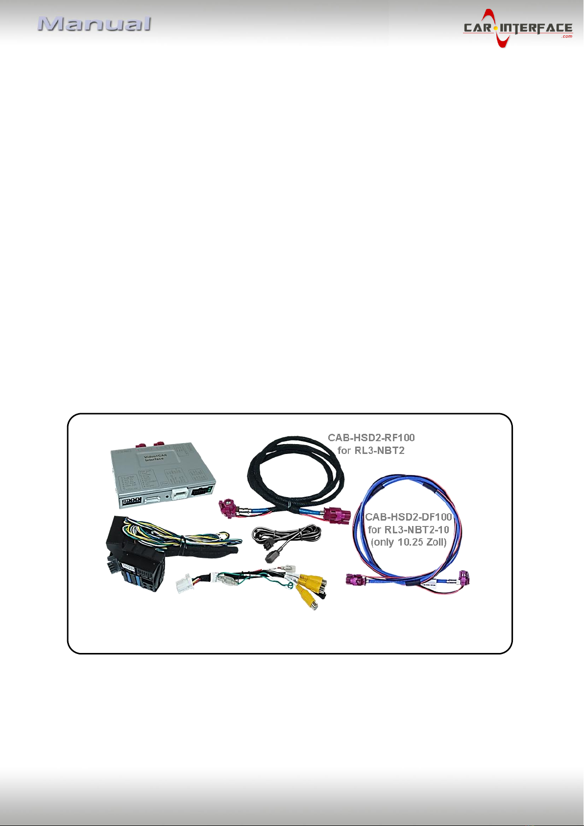
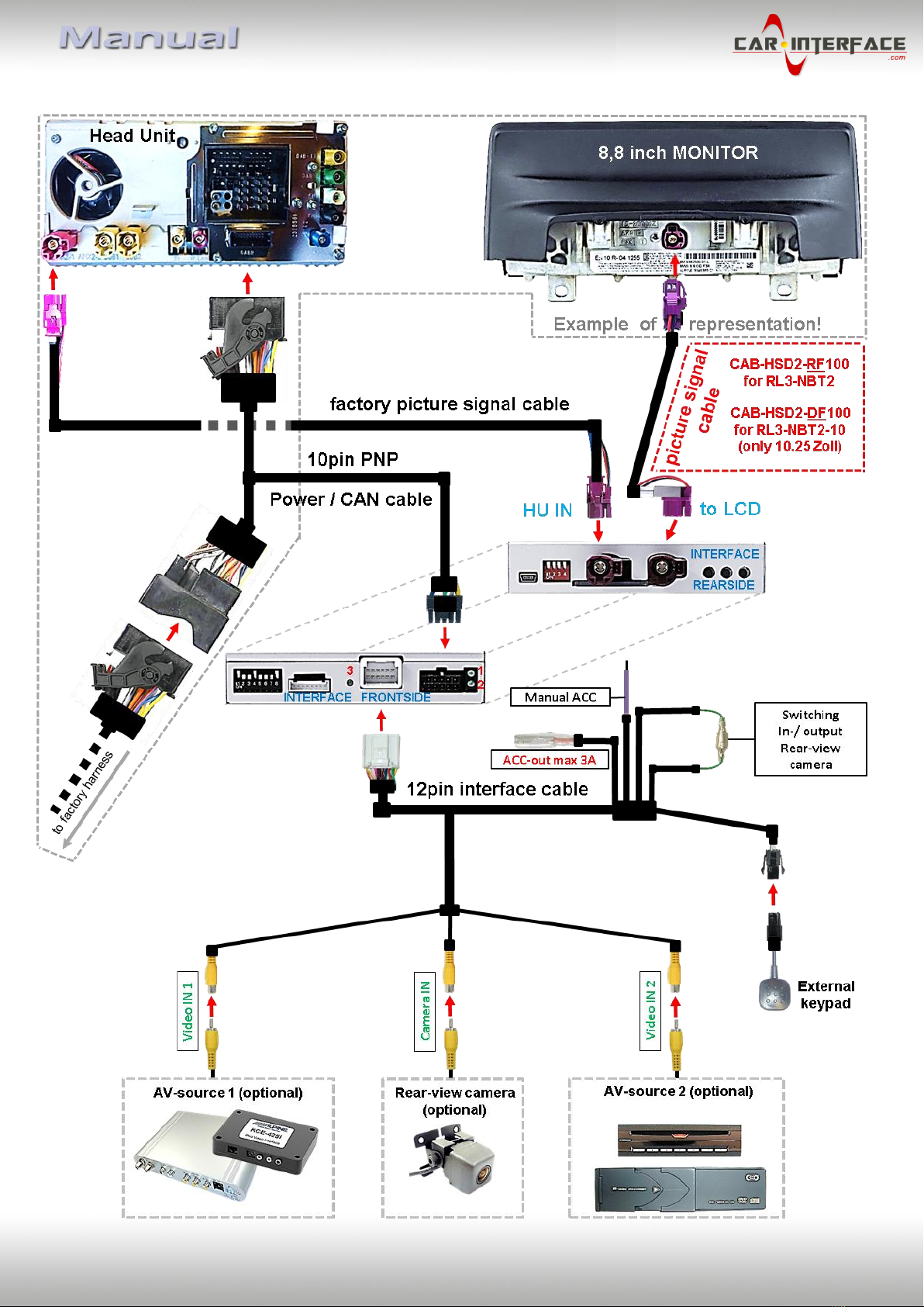
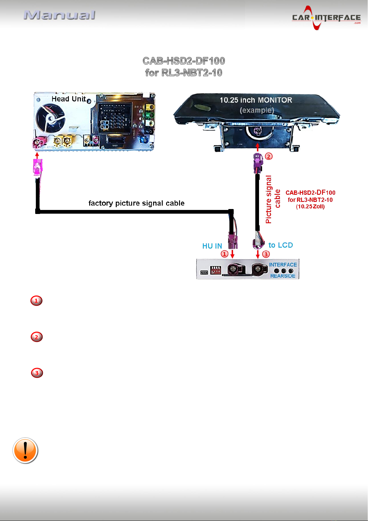
Note: For 10.25 inch monitor, the picture signal cable CAB-HSD2-DF100 has to be used.

Version 07.11.2018 HW: CAM(V97)/(V14) CI-RL3-NBT2 /CI- Rl3-NBT2-10
Page7
1.5. Settings of the 4 Dip switches (CAN functions –red)
Dip position down is ON and position up is OFF.
Fahrzeug/Navigation
Dip
1
Dip 2
Dip 3
Dip 4
BMW/Mini NBT system (with Apix)
OFF
ON
OFF
OFF
BMW NBT2 system (with Apix2)
OFF
OFF
OFF
OFF
Mini NBT2 system (with Apix2)
OFF
ON
OFF
OFF
Note: In case of absent or defective picture representation or faulty CAN communication, try
also dip switch 2 in OFF position!
After each Dip-switch-change a power-reset of the Can-box has to be performed!
2. Installation
To install the interface, first switch off the ignition and disconnect the vehicle’s battery.
Please read the owner`s manual of the car, regarding the battery`s disconnection! If
required, enable the car`s Sleep-mode (hibernation mode)
In case the sleep-mode does not succeed, the disconnection of the battery can be done
with a resistor lead.
If the necessary stabilized power supply for the interface is not taken directly from the
battery, the chosen connection has to be checked for being constantly stabile.
The interface needs a permanent 12V source!
Before a final installation, we recommend a test-run to ensure the compatibility of the
vehicle and the interface. Due to changes in the production of the vehicle manufacturer
there’s always a possibility of incompatibility.
2.1. Place of installation
The interface is supposed to be installed at a suitable location behind the vehicle`s head-
unit.

Version 07.11.2018 HW: CAM(V97)/(V14) CI-RL3-NBT2 /CI- Rl3-NBT2-10
Page8
2.2. Connection schema

Version 07.11.2018 HW: CAM(V97)/(V14) CI-RL3-NBT2 /CI- Rl3-NBT2-10
Page9
2.3. Connections to factory head-unit and monitor
2.3.1. Connection - picture signal cable
2.3.1.1. RL3-NBT2
Disconnect the factory picture signal cable’s bordeaux coloured HSD+2 connector from the
rear-side of the monitor and connect it to the bordeaux coloured HSD+2 connector
„HU IN“of the video interface .
Connect the not-angled bordeaux coloured HSD+2 connector of the enclosed picture signal
cable CAB-HSD2-RF100 to the previously become free bordeaux coloured HSD+2 connector
at the monitor’s rear side.
Connect the opposite angled bordeaux coloured HSD+2 connector of the enclosed picture
signal cable CAB-HSD2-RF100 to the bordeaux coloured male HSD+2 connector „TO LCD“of
the video interface.
Attention: The picture signal cable’s connecting direction doesn’t have an impact on the
system’s function, for that the angled and not-angled HSD+2 connectors are allowed to be
interchanged, depending on the HSD+2 connectors mounting space at the monitor.
However, mixing up/interchanging the connections of „HU IN“ and „TO LCD“ will cause
dysfunktion or even damage to the system!
Note: The colours of the HSD+2 connectors at monitor and head unit may vary.

Version 07.11.2018 HW: CAM(V97)/(V14) CI-RL3-NBT2 /CI- Rl3-NBT2-10
Page10
2.3.1.2. RL3-NBT2-10
Disconnect the factory picture signal cable’s bordeaux coloured HSD+2 connector from the
rear-side of the monitor and connect it to the bordeaux coloured HSD+2 connector
„HU IN“of the video interface .
Connect the not-angled bordeaux coloured HSD+2 connector of the enclosed picture signal
cable CAB-HSD2-DF100 to the previously become free bordeaux coloured HSD+2 connector
at the monitor’s rear side.
Connect the opposite angled bordeaux coloured HSD+2 connector of the enclosed picture
signal cable CAB-HSD2-DF100 to the bordeaux coloured male HSD+2 connector „TO LCD“of
the video interface.
Attention: The picture signal cable’s connecting direction doesn’t have an impact on the
system’s function, so that the angled and not-angled HSD+2 connectors are allowed to be
interchanged, depending on the HSD+2 connectors mounting space.
However, mixing up/interchanging the connections of „HU IN“ and „TO LCD“ will cause
dysfunktion or even damage to the system!
Note: The colours of the HSD+2 connectors at monitor and head unit may vary.

Version 07.11.2018 HW: CAM(V97)/(V14) CI-RL3-NBT2 /CI- Rl3-NBT2-10
Page11
2.3.2. Connection –Quadlock/CAN
Connect the female 10pin connector of the 10pin PNP Power / CAN cable to the 10pin
connector of the video interface.
Remove the female 40pin Quadlock connector of the vehicle harness from the rear-side of
the head-unit and connect it to the male 40pin Quadlock connector of the 10pin PNP
Power / CAN cable.
Connect the opposite female Quadlock connector of the 10pin PNP Power / CAN cable to the
previously become free male Quadlock connector at the rear-side of the head unit.

Version 07.11.2018 HW: CAM(V97)/(V14) CI-RL3-NBT2 /CI- Rl3-NBT2-10
Page12
2.4. Analog power supply for the video interface
Connect the female 12pin connector of the 12pin interface cable to the male 12pin
connector of the video interface.
Connect the red coloured wire ACC-out (max 3A) and the purple coloured wire
Manual ACC of the 12pin interface cable both to S-contact terminal 86s +12V (e.g.
glove compartment illumination).

Version 07.11.2018 HW: CAM(V97)/(V14) CI-RL3-NBT2 /CI- Rl3-NBT2-10
Page13
2.5. Connection - video sources
It is possible to connect an after-market rear-view camera and two more Video sources to
the video-interface.
Before a final installation of the video sources, we recommend a test-run to ensure the
compatibility of vehicle and interface. Due to changes in the production of the vehicle
manufacturer there’s always a possibility of incompatibility.
Connect the 12pin interface cable’s female 12pin connector to the male 12pin connector of
the video-interface.
Connect the video RCA of the video source 1 and 2 to the female RCA connector “Video IN1”
and ”Video IN 2” of the 12pin interface cable.
Connect the video RCA of the rear-view camera to the 12pin interface cable’s female RCA
connector “Camera IN”.

Version 07.11.2018 HW: CAM(V97)/(V14) CI-RL3-NBT2 /CI- Rl3-NBT2-10
Page14
2.5.1. Audio-insertion
This interface is only able to insert video signals into the factory infotainment. If an AV-
source is connected, the audio insertion has to be done by the factory audio AUX input or an
FM-modulator. The inserted video-signal can be activated simultaneously to each audio-
mode of the factory infotainment. If 2 AV sources shall be connected to the infotainment,
additional electronic is necessary to switch the audio signals.
2.5.2. After-market rear-view camera
Some vehicles have a different reverse gear code on the CAN-bus which the video-interface
is not compatible with. Therefore, there are two different ways of installation. If the video
interface receives a signal of the reverse gear, the green wire “Reverse-OUT” of the 20pin
cable should carry +12V while the reverse gear is engaged.
Note: Do not forget to set video interface’s dip5 to ON before testing.
2.5.2.1. Case 1: Interface receives the reverse gear signal
If the interface delivers +12V on the green output wire of the 12pin interface cable while
reverse gear is engaged, the video interface will automatically switch to the rear-view
camera input “Camera IN” while the reverse gear is engaged.
Additionally, the +12V (max. 3A) power supply for the rear-view camera can be taken
from the green wire of the 12pin interface cable.

Version 07.11.2018 HW: CAM(V97)/(V14) CI-RL3-NBT2 /CI- Rl3-NBT2-10
Page15
2.5.2.2. Case 2: Interface does not receive the reverse gear signal
If the video interface does not deliver +12V on the green wire of the 12pin cable when
reverse gear is engaged (not all vehicles are compatible), an external switching signal from
the reverse gear light is required. As the reverse gear light’s power supply isn’t voltage-
stabile all the time, an ordinary open relay (e.g AC-RW-1230 with wiring AC-RS5) or filter
(e.g. AC-PNF-RVC) is required. The diagram below shows the connection type of the relay.
Disconnect the green cable’s preconnected male- and female connectors of the 12pin
interface cable and connect the green input cable “Reverse-IN” to the output
connector (87) of the relay.
Note: Last but not lot least to avoid short circuits, the best solution should be, to
crimp a male 4mm connector to the relay’s output cable and connect it to the green
cable’s female 4mm connector. The output-cable “Reverse-OUT” remains
disconnected as it’s out of function.
Connect the Reverse light’s power-cable to coil (85) and the vehicle’s ground to coil
(86) of the relay.
Connect the output connector (87) of the relay to the rear-view camera’s power-
cable, like you did it to the green “Reverse-IN” cable before.
Connect stabile and permanent +12V to the relay’s input connector (30).

Version 07.11.2018 HW: CAM(V97)/(V14) CI-RL3-NBT2 /CI- Rl3-NBT2-10
Page16
2.6. Connection - video-interface and keypad
Connect the female 4pin connector of the keypad to the male 4pin connector of the
12pin interface cable.
Note: Even if switching through several video sources by the keypad mightn’t be required,
the invisible connection and availability is strongly recommended.

Version 07.11.2018 HW: CAM(V97)/(V14) CI-RL3-NBT2 /CI- Rl3-NBT2-10
Page17
2.7. Picture settings and guide lines
The picture settings are adjustable by the 3 push-buttons at the rear-side of the video-
interface. Press the MENU button to open the OSD settings menu or to switch to the next
menu item. Press UP and DOWN to change the selected value. The buttons are placed inside
in the housing to avoid accidental changes during or after the installation. Picture settings
must be done separately for AV1 and AV2 while the corresponding input is selected and
visible on the monitor.
Note: The OSD menu is only shown when a working video source is connected to the
selected video-input of the interface.
The following settings are available:
Contrast
Brightness
Saturation
Position H (horizontal)
Position V (vertical)
IR-AV1/2 (no function)
Guide L/R (no function)
UI-CNTRL (ON/OFF) guide lines
Size H/V (picture size horizontal/vertical)
Note:
To adjust the reverse picture, engage the reverse gear.
To adjust the guide lines, move the steering wheel to see the changes.
If there is no communication between interface and the vehicle`s CAN-bus (several vehicles
aren’t compatible), the reverse gear guide-lines can`t be shown during the vehicle’s
operation, even if they once appear after having switched the system to powerless!

Version 07.11.2018 HW: CAM(V97)/(V14) CI-RL3-NBT2 /CI- Rl3-NBT2-10
Page18
3. Interface operation
3.1. By factory infotainment button
To switch the interface’s activated video sources; the factory infotainment buttons can be
used.
Press the according infotainment button to switch the input from the factory video to the
inserted video sources. If all inputs are activated by dip switch settings, the order is the
following:
Factory video
Video IN 1
Video IN 2
factory video
Each press will switch to the next enabled input. Inputs which are not enabled will be
skipped.
Switchover by vehicle buttons isn’t possible in all vehicles. In some vehicles the external
keypad has to be used.
3.2. By keypad
Alternatively or additionally to the factory infotainment buttons, the interface’s external
keypad can be used to switch the enabled inputs. Even if not needed, the keypad should
always remain connected to the video interface for support purposes.

Version 07.11.2018 HW: CAM(V97)/(V14) CI-RL3-NBT2 /CI- Rl3-NBT2-10
Page19
4. Specifications
BATT/ACC range 7V - 25V
Stand-by power drain 10mA
Power 320mA @12V
Video input 0.7V - 1V
Video input formats NTSC and PAL
Temperature range -40°C to +85°C
Dimensions video-box 112 x 22 x 115 mm (W x H x D)

Version 07.11.2018 HW: CAM(V97)/(V14) CI-RL3-NBT2 /CI- Rl3-NBT2-10
Page20
5. FAQ –Trouble shooting Interface functions
For any troubles which may occur, check the following table for a solution before requesting
support from your vendor.
Symptom
Reason
Possible solution
No picture/black
picture (factory
picture).
Not all connectors have been
reconnected to factory head-
unit or monitor after
installation.
Connect missing connectors.
No power on CAN-bus box (all
LED CAN-bus box are off).
Check power supply of CAN-bus box. Check CAN-bus
connection of CAN-bus box.
CAN-bus box connected to
CAN-bus in wrong place.
Refer to the manual where to connected to the CAN-
bus. If not mentioned, try another place to connect to
the CAN-bus.
No power on video-interface
(all LED video-interface are
off).
Check whether CAN-bus box delivers +12V ACC on red
wire output of 8pin to 6pin cable. If not cut wire and
supply ACC +12V directly to video-interface.
No picture/black
picture/white picture
(inserted picture) but
factory picture is OK.
No picture from video source.
Check on other monitor whether video source is OK.
No video-source connected to
the selected interface input.
Check settings dips 1 to 3 of video interface which
inputs are activated and switch to corresponding
input(s).
LVDS cables plugged in wrong
place.
Double-check whether order of LVDS cables is exactly
connected according to manual. Plugging into head-
unit does not work when the manual says to plug into
monitor and vice versa.
Wrong monitor settings of
video-interface.
Try different combinations of dips 7 and 8 of video-
interface. Unplug 6pin power after each change.
Inserted picture totally
wrong size or position.
Inserted picture double
or 4 times on monitor.
Inserted picture
distorted, flickering or
running vertically.
Video sources output set to
AUTO or MULTI which causes
a conflict with the interfaces
auto detection.
Set video source output fixed to PAL or NTSC. It is best
to set all video sources to the same standard.
If error occurs only after
source switching: Connected
sources are not set to the
same TV standard.
Set all video sources to the same standard.
Some interfaces can only
handle NTSC input.
Check manual whether there is a limitation to NTSC
mentioned. If yes, set source fixed to NTSC output.
Inserted picture b/w.
Inserted picture qual.
bad.
Picture settings have not been
adjusted.
Use the 3 buttons and the interface's OSD to adjust the
picture settings for the corresponding video input.
Inserted picture size
slightly wrong.
Inserted picture
position wrong.
Camera input picture
flickers.
Camera is being tested under
fluorescent light which shines
directly into the camera.
Test camera under natural light outside the garage.
Camera input picture is
bluish.
Protection sticker not
removed from camera lens.
Remove protection sticker from lens.
This manual suits for next models
1
Table of contents
Other Car-Interface.com Automobile Accessories manuals

Car-Interface.com
Car-Interface.com c.LOGiC lite-Interface User manual

Car-Interface.com
Car-Interface.com CI-C1-C20 User manual

Car-Interface.com
Car-Interface.com CI-RL-LR12-TF User manual

Car-Interface.com
Car-Interface.com CI-CARPLAY-SMEG-CI User manual

Car-Interface.com
Car-Interface.com v.LOGiC CI-V5-MMI3G-PNP User manual

Car-Interface.com
Car-Interface.com CI-RL4-NG4-HU User manual

Car-Interface.com
Car-Interface.com r.LINK CI-RL3-UCON8-LV User manual

Car-Interface.com
Car-Interface.com r.LiNK User manual