Baudcom BD-E1-ETH Assembly instructions

1
MODEL BD-E1-ETH
10/100Base T-E1 Converter
User’s Reference Manual
SHANGHAI BAUDCOM COMMUNICATION DEVICE CO.,LTD
Address : Room 1101,Building 31,Lane 1508,Mei jia bang Road,Songjiang district,Shanghai ,China.
Website: http://www.baudcom.com.cn
Tel: +86 21 37709251
Fax: +86 21 37709302

2
TABLE OF CONTENTS
1 GENERAL INFORMATION
2 PRODUCT CHARACTERISTIC
3ENVIRONMENT REQUIREMENT
3.1 Power
3.2 Power consumption
3.3 E1 Interface
3.4 10/100Base-T Interface
4DIMENSIONS
5 CONFIGURATION AND OPERATION
5.1 Display of the front panel
5.2 Loop-back Button
5.3 Display of the rear panel
5.4 Dial code in the panel
5.5 Description of E1 connector
6PACKING
6.1 Packing pattern
6.2 Power Installation
7MALFUNCTION DIAGNOSES AND ELIMINATION
8APPLICATION

3
1GENERAL INFORMATION
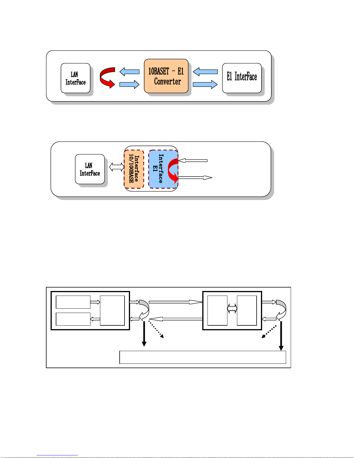
Model BD-E1-ETH is a single port E1 with Ethernet Bridging that
provides high-speed LAN-to-WAN connectivity. Plugging directly into the
10/100Base-T port of a hub or LAN switch, the E1-ETH provides E1 access at
connection data rates of 2.048 Mbps. The E1-ETH is an excellent choice for
internet access as well as LAN-to-LAN services
2 PRODUCT CHARACTERISTIC
Based on self-copyright IC.
Ethernet port 10/100M half/full duplex self adaptable, supporting VLAN.
RJ45 interface supports AUTO-MDIX.
Provides 2 clock types: E1 master clock, E1 line clock.
Provide LAN auto reset function, run more stably.
Has the function of pseudo-random code testing, convenient for opening of
the circuit, and can be used as an error code instrument.
Have three Loop-Back Modes: E1 interface Loop-Back (ANA)、LAN
interface Loop-Back (DIG)、command the remote LAN interface
Loop-Back (REM) .
E1 connector support (BNC)75ohm/(RJ45)120ohm adapt ;
With abundant presentation function of Ethernet data, can detect real-time
data communication status.

4
3 ENVIRONMENT REQUIREMENT
The temperature requirement is not very strict, the device can be working well
under terrible environment.
working temperature: 0°C - 50°C
relative humidity: 95%(without coagulation)
No erosive and impregnant gas, no rising dust, no strong magnetic field
disturbing
3.1 Power
Adapting module power, voltage range can be wide, with strong ant-jamming
function.
With good insulation, stable working status is available
power: -48V type, input voltage: -36V~-72V
power: 220V type, input voltage: 90V~260V
3.2 Power consumption
Total device consumption: <5W
3.3 E1 Interface
Line Rate: 2.048Mbps±50ppm
Line Code : HDB3
Interface Standard: ITU-T G.703
E1 Impedance : 75Ω(unbalance) and 120Ω(balance)
Connections :BNC and RJ45
5
Jitter tolerance : finer than G.742 and G.823
3.4 10/100Base-T Interface
Rate: 10/100M, full/duplex auto-negotiation
Protocol: Support IEEE 802.3, IEEE 802.1Q (VLAN)
MAC Address Entiries: 4096 Entiries
Total Memory Sizes: 64MBits SDRAM
Physical interface: RJ45, support AUTO-MDIX
4. DIMENSIONS
210(W) ×140 (L) x 30(H) mm
5. CONFIGURATION AND OPERATION
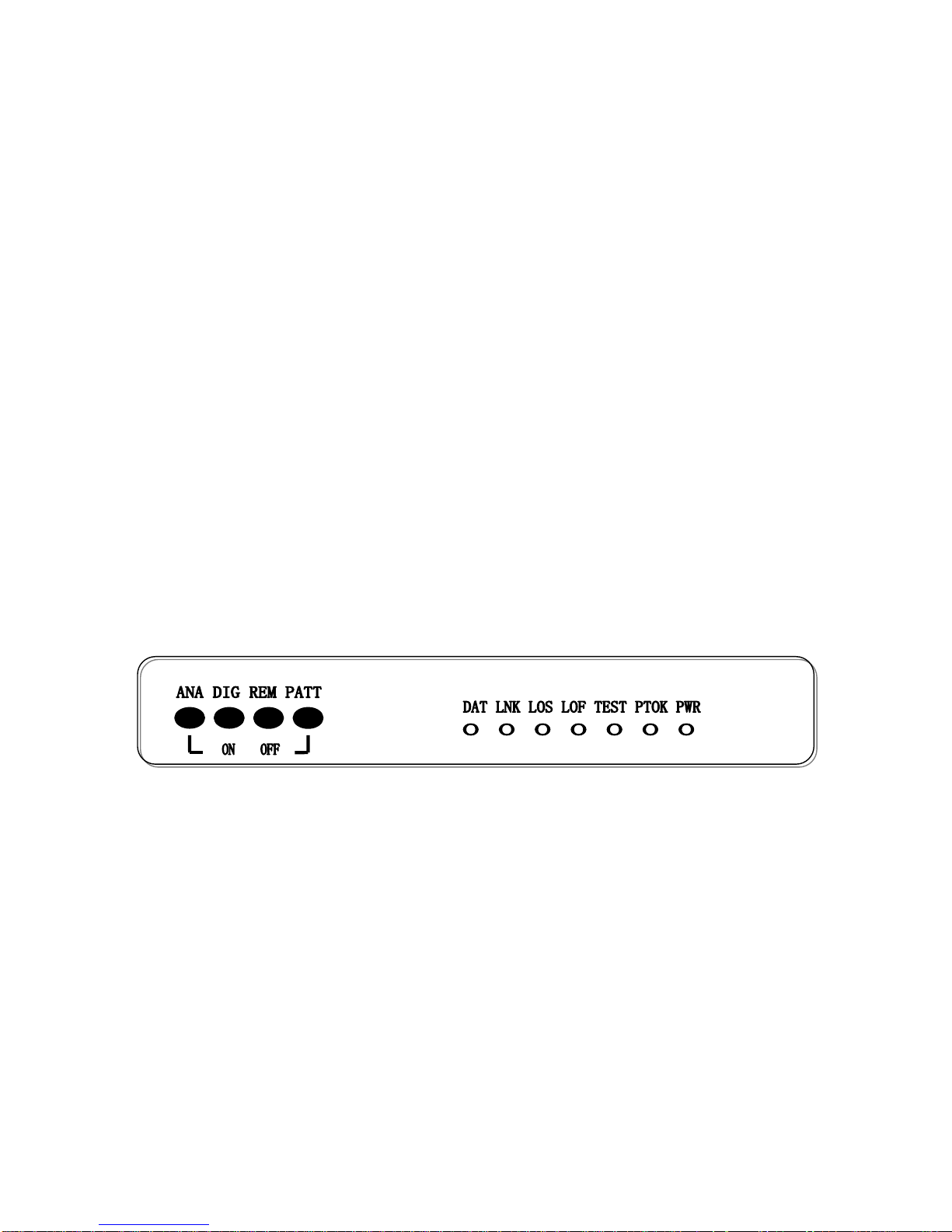
5.1 Display of the front panel

6
5.2 LED Indicator
There are 7 indicator LED on front panel.
From left to right is as following:
Name
Color
Status
Description
DAT
green
flick
E1 port has date receive and transmit
On/off
E1 port has no date receive and transmit
LNK
yellow
Flick/on
Indicates Ethernet has connected
off
Ethernet has no connect
LOS
red
ON
E1 signal loss
OFF
E1 signal normal
LOF
reserved
TEST
yellow
ON
Under test status(ANA, DIG, REM, PATT pressed any)
OFF
In normal working status
PTOK
green
ON
PATT pressed, PATT test normal
OFF
PATT pressed, PATT test not normal
Wink
PATT pressed, PATT test has error code
PWR
green
ON
Power ON
OFF
Power not ON
5.3 loop-back button
There are four loop-back button on the front panel, they are as following from
the left to right,
ANA: E1 Interface local-back loop, to check whether local device and its
connecting circuit correct
7
DIG: 10/100BASE-T Local loop-back, to check the opposite device and E1 circuit
REM: E1 interface loop-back outward to test E1 line
PATT: PBRS test. To produce and transmit the PBRS to the 10/100BASE input
connector, and to check whether the output signal of the 10/100BASE accord
with PBRS standard. If according, the PTOK light on, otherwise, off. By this
way, the status of E1 Line can be tested.
Push the PATT button, when loop circuit 1 is on, If PTOK is on , indicates device
works well ; loop circuit 1 off and loop circuit 2 on, indicates that fiber transmission
circuit and both side device work well
E1 LINE
PBRS Code
REC & CHK
E1
Interfa
ce
E1Int
10BInt
When testing, one of above loop back must be on
Loop 1
Loop 2
E1 line

8
Note:
when the test LED on, the normal communication will be terminated
During the PATT model testing, the circuit should be cycle by itself,
otherwise, the PATT code can’t come back.
5.4 Display of the rear panel
Rear panel(AC 220V)
Real panel(DC -48V)
Power of AC220V/ DC-48V is suitable for the device. If the power of
DC-48V is used, the positive and negative terminal can be optional because there is
the self-test circuit for the polarity inside the device.
Note:
TX —— E1 75Ω unbalance/120 balanceΩ, Transmit BNC/RJ45 Interface
RX —— E1 75Ω unbalance/120 balanceΩ, Receive BNC/RJ45 Interface
10/100Base-T —— 10/100Base-T Interface, RJ45
5.5 Dial code in the panel
On the panel, there are 8 digital DIP switches to set E1 clk.

9
1 (clk1):E1 master clock and line clock set
E1 clock set
Clk1
Master (main clock)
OFF
Slave (line clock)
ON
Note pls: during communicating, one master and one
slave is necessary and the rate of the slave will follow the
master
2 (clk2):
LAN set
Clock2
10/100M full/duplex auto-negotiation
OFF
10M full/duplex auto-negotiation
ON
NOTE:
If clock mode is line ,the rate of the device will follow the main
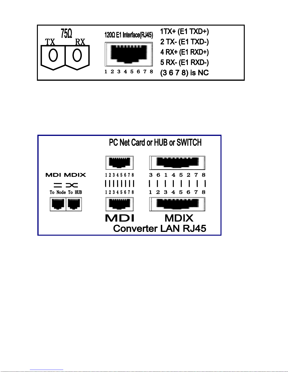
5.6 Description of E1 connector
E1 Interface impedance support 75ohm/120ohm adapt.
Note: the pins of 120ohm see as following:
10
LAN Interface
In the back panel there are two RJ45 jack, one is for DTE mode (MDI) the
other is for DCE mode (MDIX), easy for you to use it
6 PACKING
6.1 Packing pattern
The following are things listed in each package:
E1-10/100BT Converter 1
AC220V power wire 1
User’s manual 1
BNC 2
Table of contents
Other Baudcom Media Converter manuals


