DK50
08/2014 - 7 - SM-DK50-EN-1-08-2014-MD
PE NU
NX1
U1
FU
YV1
EV1 CB1
X2234
1/N/PE ~ 230 V 50..60 Hz
ST
40°C p >
150°C
M
PE 213
Z2 U2
SP
Z1 U1
DK50 Z, DK50-10Z, DK50 S, DK50-10S
PE N UYV1
EV1 B1
C
NUX1 1
FU
X2
234
CB2
150°C
ST
40°C p >
PE 213
Z2 U2
SP
Z1 U1
M
DK50 Z, DK50-10Z, DK50 S, DK50-10S
ELECTRIC OBJECT OF 1st CAT.
B TYPE ELECTRIC OBJECT OF 1st CAT.
B TYPE
1/N/PE ~ 110 V 60 Hz
DK50-10Z/M, DK50-10S/M
NPE UEV1 C
EV2 YV1 B1
N U 1X1 2
FU
1/N/PE ~ 230 V 50..60 Hz
SP
40°C p >
ST
34X2
2PE 3
1
M
Z1
Z2 U2
U1
150°C
1/N/PE ~ 115 V 60 Hz
C
N
PE UEV1 EV2 YV1 B1 B2
C
FU
X1
NU1234X2
2
PE 31
SP
40°C p >
ST M
Z1
Z2 U2
U1
150°C
DK50-10Z/M, DK50-10S/M
ELECTRIC OBJECT OF 1st CAT.
B TYPE ELECTRIC OBJECT OF 1st CAT.
B TYPE
Dental compressor with base DK50 Z, DK50-10 Z (Fig.4)
After removing all packaging material, place the product on the floor and remove stabilization parts X and Y
(Detail A). Direct the output pressure hose, drain hose and power cord out the back of the compressor.
Dental compressor with base DK50-10 Z/M (Fig.2, Fig.4)
After removing all packaging material, place the product on the floor and remove stabilization parts X and Y
(Detail A). Direct the output pressure hose and power cord out the back of the compressor. Install the
magnetic holder (16) with a vessel (20) to capture condensate from the dryer on the side of the cooler.
Dental compressor in box DK50 S, DK50-10 S (Fig.4)
After removing all packaging material, place the product on the floor and remove stabilization parts X and Y
(Detail A). Direct the output pressure hose, drain hose and power cord out the back of the compressor. Slide
the box over the compressor so that the front face of the box matches the front part of the compressor and
the box is fully seated. Make sure that the pressure hose, drain hose and electric cord come out via the
opening at the back of the box. Position the drain hose with its valve in the holder at the rear of the box.
Dental compressor in box DK50-10 S/M (Fig.4)
After removing all packaging material, place the product on the floor and remove stabilization parts X and Y
(Detail A). Direct the output pressure hose, drain hose and power cord out the back of the compressor. Fit
the housing over the top of the compressor, connect the flexible shaft to the control button, fasten with the
screw and put the lid on the cabinet housing (see picture). Make sure that the pressure hose, drain hose and
electric cord come out via the opening at the back of the box. Connect the condensate drain hose to the
vessel (20). The magnetic holder (16) with a vessel (20), for entrapping condensate from a dryer may be
fixed at the sides of housing or from the front on its doors. When fixing the holder with a vessel at the
housing side it is necessary to consider a space of at least 11 cm between the housing and furniture.
Distance smaller than the specified one may cause problem with handling of the vessel.
The vessel must always be installed so that the lower section is near the floor; any
other installation may damage the dryer!
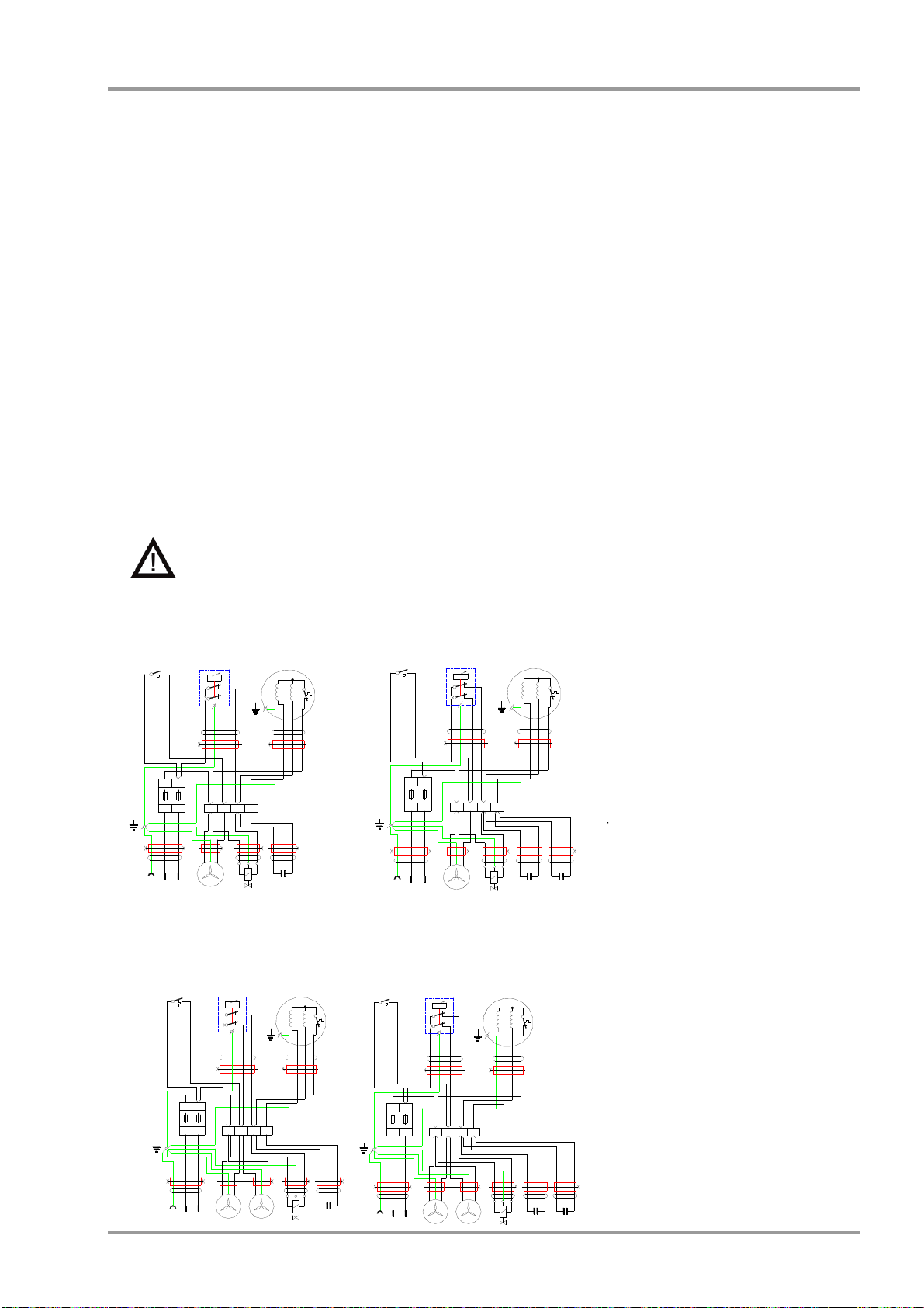
5. WIRING DIAGRAMS
M Motor of compressor
EV1 Fan of compressor
EV2 Fan of dryer
YV1 Solenoid valve of compressor
FU Fuses 230/50-60 (T10A)
110/50-60 (T16A)
ST Thermo switch
CB1,CB2 Capacitor
SP Pressure switch
X1,X2 Terminal