Bauer Kompressoren Verticus 5 Guide
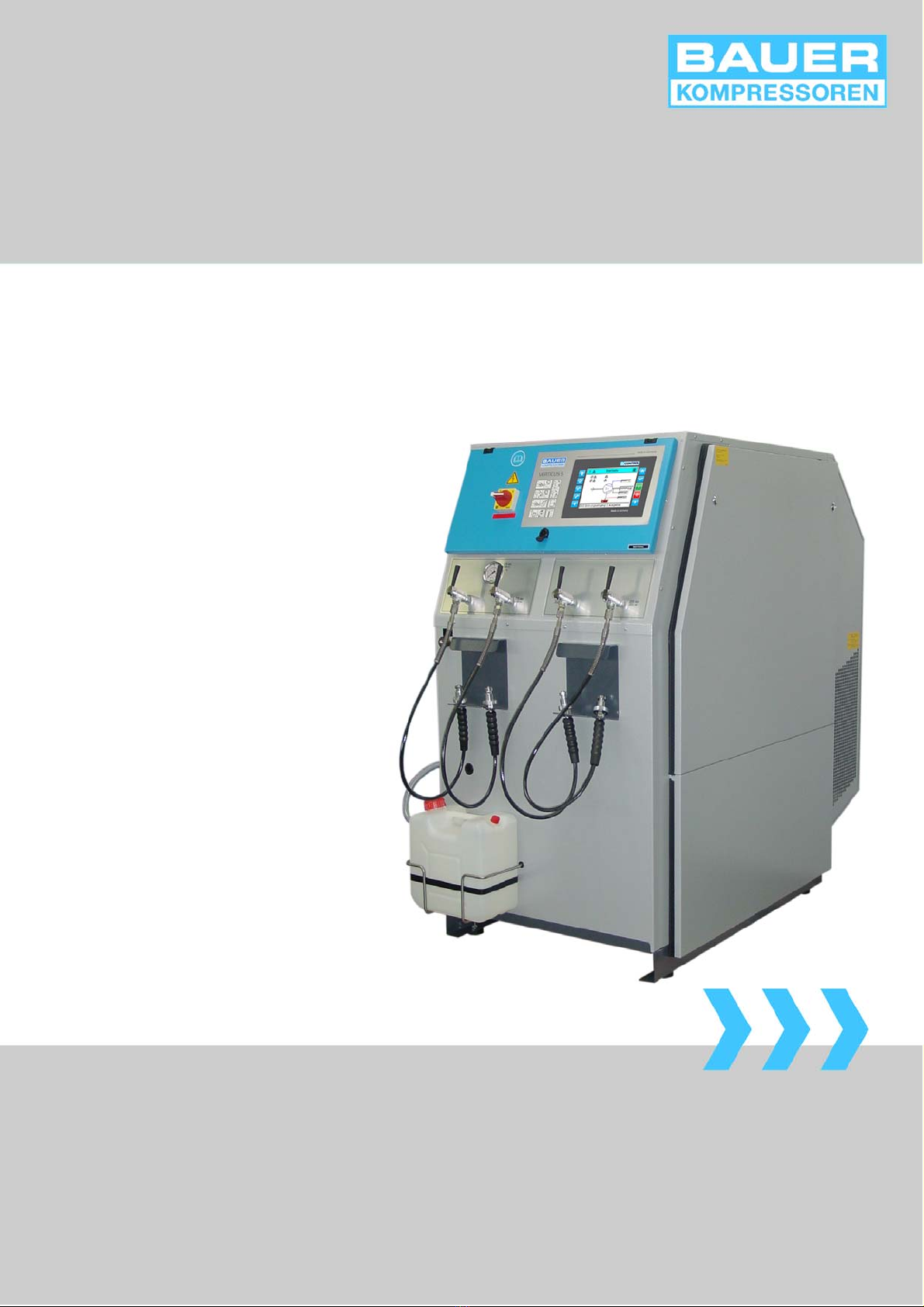
Verticus 5
High Pressure Compressors for Breathing Air
Operating Manual and Spare Parts Catalog
Copyright 2014 BAUER Kompressoren GmbH München
225 bar
330 bar
420 bar


A
B
C
D
E
F
G
DESCRIPTION
INSTALLATION, TAKING INTO OPERATION
OPERATION
MAINTENANCE, REPAIR
STORAGE, PRESERVATION
DIAGRAMS, DRAWINGS
SPARE PARTS CATALOGUE


V5−A/05/14
Instruction Manual wVERTICUS 5 Compressor Units
i
INTRODUCTION
This manual contains operating instructions and mainte
nance schedules for the breathing air compressor units of
the model range
Model: _________________________
Serial no.: _________________________
WARNING
! Pneumatic high pressure system !
The breathing air produced with the compressor units de
scribed in this manual is subject to strict quality standards.
Ignoring the operating and maintenance instructions can
lead to severe injury or death.
The machine has been built in accordance with the EC ma
chine regulations 2006/42/EC. Specifications on the noise
level in accordance with the machine and product safety
law as of 01.05.2004 and the EC machine regulations,
chapt. I, section 1.7.4. The machine has been built accord
ing to the highest standard of technology and the gener
ally acknowledged safety standards. Nevertheless, opera
tion could still cause danger for the operating personnel or
third parties, or result in damage to the machine and other
values. The machine may only be used to produce com
pressed air as specified in this manual. Other use is strictly
prohibited.
Edition May 2014
2014 BAUER Kompressoren GmbH, München
All rights reserved
VERTICUS 5

Instruction Manual wVERTICUS 5 Compressor Units
ii
INTRODUCTION
NOTICE
Layout and use of instruction manuals
Working with pneumatic high pressure systems cannot always be considered safe and one should possess a
minimum knowledge of how to operate them. For this reason, please read this instruction manual before oper
ating your unit, to get to know the components and processes.
This instruction manual is made up according to the building block principle. It is divided into 7 sections, whose
content varies according to the type of unit, standard or special and of course the accustomized extras, which
are available for all our units in large numbers. With this kind of subdivision system, all sections should be in
existence, in order to give a complete picture. In other words: even if one particular component is not part of
the unit, the relative section will still be kept, although only a notice may be printed there. On the other hand,
other sections could be represented more than once if certain units require this. In such a case one only has
to refer to the applicable section, all superfluous ones can be removed. This is quite simple due to the ring
binding system.
Please note that the circuit diagrams in section F, unless otherwise stated, are the standard circuit diagrams
for your specific unit. So please always refer to the circuit diagram enclosed in the compressor unit control box,
in which any possible changes are registered.
The same thing applies for the spare parts lists in section G. To avoid misunderstanding when ordering spare
parts, we advise you to remove the parts that are not applicable. The spare parts lists that apply to the relative
unit are listed in the section Index.

Instruction Manual wVERTICUS 5 Compressor Units
iii
TABLE OF CONTENTS
A. DESCRIPTION A-3............................................................................
1. GENERAL A-3................................................................................
1.1. PURPOSE AND SHORT DESCRIPTION A-3..........................................................
1.2. DESIGN AND MODE OF OPERATION A-3...........................................................
2. LUBRICATION SYSTEM A-15...................................................................
2.1. FUNCTIONAL DESCRIPTION A-15..................................................................
2.2. TYPE OF OIL A-15..............................................................................
3. INTAKE FILTER A-16...........................................................................
3.1. FUNCTIONAL DESCRIPTION A-16..................................................................
4. INTERMEDIATE SEPARATORS A-16.............................................................
4.1. FUNCTIONAL DESCRIPTION A-17..................................................................
4.2. 1ST STAGE SEPARATOR (OPTION) A-17.............................................................
5. FINAL SEPARATOR / FILTER SYSTEM A-17.......................................................
5.1. GENERAL A-17.................................................................................
5.2. Application and summary description A-17.........................................................
5.3. OIL AND WATER SEPARATOR A-18................................................................
6. PRESSURE MAINTAINING / NON-RETURN VALVE A-18............................................
6.1. COMPRESSOR UNITS UP TO 350 BAR A-18..........................................................
6.2. COMPRESSOR UNITS UP TO 420 BAR A-18..........................................................
7. SAFETY VALVES A-19.........................................................................
8. PRESSURE GAUGES A-19.......................................................................
8.1. INTERMEDIATE PRESSURE GAUGES A-19...........................................................
8.2. FINAL PRESSURE GAUGE A-19....................................................................
8.3. OIL PRESSURE GAUGE A-19......................................................................
9. VALVES A-19.................................................................................
10. AUTOMATIC CONDENSATE DRAIN A-21.........................................................
10.1. COMPRESSOR BLOCKS IK12.14, IK150, IK15.1, IK180 A-21............................................
10.2. COMPRESSOR BLOCK IK15.11 A-22...............................................................
10.3. COMPRESSOR BLOCK IK18.1 A-23................................................................
10.4. START UNLOADING A-25........................................................................
10.5. STANDSTILL DRAINAGE A-25.....................................................................
10.6. CONDENSATE COLLECTOR 10 ltrs. A-25............................................................
10.7. CONDENSATE COLLECTOR 40 ltrs. (OPTIONAL) A-25..................................................
10.8. Condensate disposal A-27.......................................................................
10.9. ELECTRICAL CONNECTION A-27..................................................................
11. ELECTRICAL SYSTEM A-28.....................................................................
11.1. GENERAL A-28.................................................................................
11.2. EMERGENCY SHUTDOWN A-28...................................................................
11.3. B-CONTROL MICRO (standard for all Verticus 5 compressor units) A-28..................................
11.4. COMPRESSOR CONTROLLER B-CONTROL II (optional extra for all Verticus 5 compressor units) A-47...........
12. COMPRESSOR DRIVE SYSTEM A-66.............................................................
13. COOLING SYSTEM A-66........................................................................
13.1. TECHNICAL DATA A-67.........................................................................

Instruction Manual wVERTICUS 5 Compressor Units
iv
TABLE OF CONTENTS
B. INSTALLATION, OPERATION B-3..............................................................
1. INSTALLATION B-3..........................................................................
1.1. COMPRESSOR ROOM CONDITIONS B-3...........................................................
1.2. LOCATING THE UNIT B-3.......................................................................
1.3. COOLING AIR DUCT INSTALLATION B-3...........................................................
1.4. AIR BAFFLE CONTROL (Option) B-3...............................................................
1.5. NATURAL VENTILATION B-4....................................................................
1.6. ARTIFICIAL VENTILATION B-6...................................................................
2. ELECTRICAL INSTALLATION B-7...............................................................
3. CONNECTING EXTERNAL FILLING PANELS (OPTIONAL) B-8......................................
4. CONNECTING STORAGE BOTTLES (OPTIONAL) B-9..............................................
5. TAKING INTO OPERATION B-9................................................................
5.1. PREPARATION FOR OPERATION B-9..............................................................
C. OPERATION C-3.............................................................................
1. SAFETY MEASURES C-3.......................................................................
1.1. NOTES AND WARNING SIGNS C-3................................................................
1.2. IDENTIFYING THE SAFETY NOTICES C-3...........................................................
1.3. FUNDAMENTAL SAFETY NOTICES C-3.............................................................
1.4. SAFETY REGULATIONS (EC; partly Germany, only) C-7...............................................
2. OPERATION C-8.............................................................................
2.1. PREPARATION FOR OPERATION C-8..............................................................
2.2. STARTING THE UNIT (B-CONTROL) C-8............................................................
2.3. OPERATION C-9..............................................................................
2.4. SWITCHING THE UNIT OFF C-10..................................................................
2.5. FILLING PROCEDURE C-11.......................................................................
D. MAINTENANCE, REPAIR D-3..................................................................
1. GENERAL D-3................................................................................
1.1. MAINTENANCE RECORD D-3....................................................................
1.2. MAINTENANCE WORK D-3.....................................................................
1.3. MAINTENANCE INTERVALS D-3..................................................................
2. LUBRICATION SYSTEM D-3...................................................................
2.1. OIL LEVEL CHECK D-3..........................................................................
2.2. OIL CHANGE INTERVALS D-4....................................................................
2.3. OIL CAPACITY D-4.............................................................................
2.4. OIL PACKAGES D-4............................................................................
2.5. OIL CHANGE D-4..............................................................................
2.6. CHANGING THE OIL TYPE D-4...................................................................
2.7. VENTING OIL PUMP D-4........................................................................
3. INTAKE FILTER D-5...........................................................................
3.1. MAINTENANCE D-5............................................................................
4. INTERMEDIATE SEPARATORS D-6.............................................................
4.1. MAINTENANCE D-6............................................................................

Instruction Manual wVERTICUS 5 Compressor Units
v
TABLE OF CONTENTS
5. FINAL SEPARATOR / FILTER SYSTEM D-7.......................................................
5.1. OIL AND WATER SEPARATOR D-7................................................................
5.2. PURIFIER D-7.................................................................................
6. PRESSURE MAINTAINING / NON-RETURN VALVE D-13............................................
6.1. Maintenance D-13.............................................................................
7. SAFETY VALVES D-13.........................................................................
7.1. OPERATING CHECK D-13........................................................................
7.2. BLOW-OFF PRESSURE CHECK D-13................................................................
8. PRESSURE GAUGES D-14.......................................................................
9. VALVES D-14.................................................................................
9.1. GENERAL INSTRUCTIONS FOR CHANGING THE VALVES D-14...........................................
9.2. Changing the valves D-14.......................................................................
9.3. VALVE CHANGE D-14...........................................................................
10. AUTOMATIC CONDENSATE DRAIN D-14.........................................................
10.1. GENERAL D-14.................................................................................
10.2. MAINTENANCE D-14............................................................................
10.3. ACTIVATED CHARCOAL ELEMENT MAINTENANCE D-14...............................................
10.4. ACTIVATED CHARCOAL MAINTENANCE D-14.......................................................
10.5. FLOAT SWITCH MAINTENANCE D-15..............................................................
11. ELECTRICAL SYSTEM D-15.....................................................................
11.1. DRIVE MOTOR D-15............................................................................
11.2. ELECTRIC CONTROL D-15........................................................................
11.3. Pressure switch D-15............................................................................
11.4. B-CONTROL BATTERY REPLACEMENT D-15.........................................................
12. COMPRESSOR DRIVE SYSTEM D-16.............................................................
12.1. ELECTRIC DRIVE MOTOR D-16....................................................................
12.2. V-BELTS D-16..................................................................................
13. MAINTENANCE ON FILLING VALVES D-16.......................................................
13.1. FILLING VALVES ON V5 FILLING PANEL D-16........................................................
13.2. FILLING VALVES ON EXTERNAL FILLING PANEL D-17..................................................
14. MAINTENANCE OF STORAGE BOTTLES D-17.....................................................
14.1. LIFETIME D-17.................................................................................
14.2. INSPECTIONS D-18.............................................................................
14.3. CONDENSATE DRAIN D-18.......................................................................
15. REPAIR INSTRUCTIONS D-18...................................................................
16. TROUBLE-SHOOTING D-19.....................................................................
17. TABLES D-39.................................................................................
17.1. TIGHTENING TORQUE VALUES D-39...............................................................
17.2. TORQUE SEQUENCE D-39........................................................................
17.3. LUBRICATION CHART D-40......................................................................
17.4. ADHESIVE AND SEALANT CHART D-40.............................................................
17.5. TESTING AGENTS D-40..........................................................................

Instruction Manual wVERTICUS 5 Compressor Units
vi
TABLE OF CONTENTS
E. STORAGE, PRESERVATION E-3................................................................
1. GENERAL E-3................................................................................
2. PREPARATION E-3...........................................................................
3. PRESERVING THE COMPRESSOR E-3...........................................................
4. PRESERVING THE MOTOR/ENGINE E-3.........................................................
5. PREVENTIVE MAINTENANCE DURING STORAGE E-3.............................................
5.1. CHANGING THE LUBE OIL FOR PRESERVING E-3....................................................
6. REACTIVATING THE COMPRESSOR UNIT E-3...................................................
7. TRANSPORTATION E-4.......................................................................
F. DIAGRAMS, DRAWINGS F-3..................................................................
1. FLOW DIAGRAMS F-3........................................................................
2. DRAWINGS F-3..............................................................................
3. LISTS F-3...................................................................................
4. SCHEMATIC DIAGRAMS F-3...................................................................
G. PARTS LISTS G-3.............................................................................
1. COMPRESSOR UNITS G-3.....................................................................
1.1. COMPRESSOR UNIT V 12.14 G-3.................................................................
1.2. COMPRESSOR UNIT V 150 G-3...................................................................
1.3. COMPRESSOR UNIT V 180 G-4...................................................................
1.4. COMPRESSOR UNIT V 15.1 G-4..................................................................
1.5. COMPRESSOR UNIT V 15.11 G-5.................................................................
1.6. COMPRESSOR UNIT V 18.1 G-5..................................................................
1.7. COMPRESSOR UNIT V 12.14 Super-Silent G-6......................................................
1.8. COMPRESSOR UNIT V 150 Super-Silent G-6........................................................
1.9. COMPRESSOR UNIT V 180 Super-Silent G-7........................................................
1.10. COMPRESSOR UNIT V 15.1 Super-Silent G-7........................................................
1.11. COMPRESSOR UNIT V 15.11 Super-Silent G-8......................................................
1.12. COMPRESSOR UNIT V 18.1 Super-Silent G-8........................................................

Instruction Manual wVERTICUS 5 Compressor Units
vii
TABLE OF FIGURES
Fig. 1 Compressor unit, V series Super-Silent; front view, condensate collector fitted A-4.....................
Fig. 2 Compressor unit, V series open; rear view A-5...................................................
Fig. 3 Compressor unit, V series Super-Silent; front view, with top mounted B-KOOL and cooling air duct A-6....
Fig. 4 Filling panel with 2 pressure ranges and switch-over valve A-7......................................
Fig. 5 External filling panel, design for open housing 300 bar with B-CONTROL Control unit A-8..............
Fig. 6 External filling panel; 6x 300 bar, 4x 200 bar with B-CONTROL Control unit A-9......................
Fig. 7 Compressor block IK12.14 A-10................................................................
Fig. 8 Compressor block IK150, front view A-11........................................................
Fig. 9 Compressor blocks IK15.1, IK15.11, front view A-12...............................................
Fig. 10 Compressor block IK180, front view A-13........................................................
Fig. 11 Compressor block IK18.1, front view A-14.......................................................
Fig. 12 Lube oil circuit, IK12.14 A-15..................................................................
Fig. 13 Lube oil system IK150 to IK18.1 A-15...........................................................
Fig. 14 Intake filter, IK12.14 A-16.....................................................................
Fig. 15 Intake filter, IK150, IK180, IK18.1 A-16..........................................................
Fig. 16 Filter system with SECURUS monitoring A-17.....................................................
Fig. 17 Pressure maintaining/non-return valve, 350 bar A-18..............................................
Fig. 18 Pressure maintaining/non-return valve, 420 bar A-18..............................................
Fig. 19 Final pressure gauge A-19.....................................................................
Fig. 20 Valve operation A-19........................................................................
Fig. 21 Valve head 1st stage A-20....................................................................
Fig. 22 Automatic condensate drain unit A-21..........................................................
Fig. 23 Normal operation A-21.......................................................................
Fig. 24 Condensate drain A-22.......................................................................
Fig. 25 Automatic condensate drain unit IK15.11 A-22...................................................
Fig. 26 Normal operation A-23.......................................................................
Fig. 27 Condensate drain A-23.......................................................................
Fig. 28 Automatic condensate drain unit IK18.1 A-24....................................................
Fig. 29 Drain valve 2nd stage, IK18.1 A-24.............................................................
Fig. 30 Normal operation A-25.......................................................................
Fig. 31 Condensate drain A-25.......................................................................
Fig. 32 Condensate collector, 40 ltrs. A-26.............................................................
Fig. 33 Float switch orientation A-26..................................................................
Fig. 34 Condensate collector, function A-26............................................................
Fig. 35 B-Control Micro A-28........................................................................
Fig. 36 Operating and display elements A-30...........................................................
Fig. 37 Start page A-31.............................................................................
Fig. 38 B-Control control panel and display A-47........................................................
Fig. 39 Operating and display elements A-48...........................................................
Fig. 40 CF card removal A-49........................................................................
Fig. 41 Connections A-49...........................................................................
Fig. 42 Home page A-50............................................................................
Fig. 43 Alarm list, confirmed A-50....................................................................
Fig. 44 Alarm list, not confirmed A-50.................................................................
Fig. 45 Compressor installation data A-51..............................................................
Fig. 46 Main menu A-51............................................................................
Fig. 47 Actual values 1 A-52.........................................................................
Fig. 48 Actual values 2 A-52.........................................................................
Fig. 49 Actual values 3 A-52.........................................................................
Fig. 50 Trend page A-53............................................................................
Fig. 51 Logbook page A-53..........................................................................
Fig. 52 Log-in page A-54............................................................................
Fig. 53 Keyboard A-54..............................................................................
Fig. 54 Log-in page, configuration level A-54...........................................................
Fig. 55 Operation menu A-55........................................................................
Fig. 56 Operation modes A-55.......................................................................

Instruction Manual wVERTICUS 5 Compressor Units
viii
TABLE OF FIGURES
Fig. 57 Control settings A-56........................................................................
Fig. 58 Pressure values A-56.........................................................................
Fig. 59 Combined operation A-57....................................................................
Fig. 60 Combination pressure A-57...................................................................
Fig. 61 Service menue A-58..........................................................................
Fig. 62 Maintenance page A-58......................................................................
Fig. 63 Logbook export page A-58....................................................................
Fig. 64 Diagnosis page A-59.........................................................................
Fig. 65 Pre-lubrication page A-59.....................................................................
Fig. 67 Setup page 1 A-60...........................................................................
Fig. 68 Setup page 2 A-60...........................................................................
Fig. 69 Sensors A-60...............................................................................
Fig. 70 Valves A-61................................................................................
Fig. 71 B-Messenger A-61...........................................................................
Fig. 72 Message filter A-61..........................................................................
Fig. 73 B-VPN A-62................................................................................
Fig. 74 Bus communication A-62.....................................................................
Fig. 75 Backup A-62................................................................................
Fig. 76 Display Setup A-63..........................................................................
Fig. 77 Calibrating the Touch Panel A-63...............................................................
Fig. 78 Hex switch, operating mode position A-63.......................................................
Fig. 79 System Setup A-64..........................................................................
Fig. 80 Set time A-64...............................................................................
Fig. 81 Logger page A-64...........................................................................
Fig. 82 Securus page A-65...........................................................................
Fig. 83 Seccant page A-65..........................................................................
Fig. 84 Cooling air flow A-66........................................................................
Fig. 85 Room temperature B-3......................................................................
Fig. 86 Locating the unit B-3.......................................................................
Fig. 87 Installation (natural ventilation) B-4............................................................
Tab. 1 Air intake and outlet openings B-4...............
Fig. 88 Installation with natural ventilation, example 1 B-5...............................................
Fig. 89 Installation with natural ventilation, example 2 B-5...............................................
Fig. 90 Installation with natural ventilation, example 3 B-5...............................................
Fig. 91 Installation (artificial ventilation) B-6...........................................................
Fig. 92 Installation with artificial ventilation, example 1 B-7..............................................
Fig. 93 Installation with artificial ventilation, example 2 B-7..............................................
Fig. 94 B-CONTROL-Control unit B-8................................................................
Fig. 95 Control panel, B-Control Micro C-8............................................................
Fig. 96 Control panel, B-Control II C-9................................................................
Fig. 97 Scavenging valve C-11.......................................................................
Fig. 98 International filling connector C-12.............................................................
Fig. 99 Connecting air bottle C-12....................................................................
Fig. 100 Filling air bottle C-12.........................................................................
Fig. 101 Removing air bottle C-12.....................................................................
Fig. 102 Oil sight gauge IK12.14 D-4..................................................................
Fig. 103 Oil sight gauge IK150, IK15.1, IK15.11, IK180, IK18.1 D-4.........................................
Fig. 104 Oil filler, IK12.14 D-5........................................................................
Fig. 105 Oil filler, IK150, IK15.1, IK15.11, IK180, IK18.1 D-5...............................................
Fig. 106 Removing the cover D-5.....................................................................
Fig. 107 Replacing the oil filter D-5...................................................................
Fig. 108 Intake filter, IK12.14 D-6.....................................................................
Fig. 109 Intake filter, IK150, IK15.1, IK15.11, , IK180, IK18.1 D-6..........................................
Fig. 110 Oil and water separator, 420 bar D-7..........................................................
Fig. 111 Removing the filter head D-8.................................................................
Fig. 112 Extracting the cartridge D-8..................................................................

Instruction Manual wVERTICUS 5 Compressor Units
ix
TABLE OF FIGURES
Fig. 113 Pressure maintaining/non-return valve 350 bar D-13...............................................
Fig. 114 Final pressure safety valve, 225 and 330 bar D-13.................................................
Fig. 115 Final pressure safety valve, 420 bar D-13........................................................
Fig. 116 Final pressure switch D-15....................................................................
Fig. 117 Removing cover D-15........................................................................
Fig. 118 Taking out the battery D-16...................................................................
Fig. 119 Battery handling D-16........................................................................
Fig. 120 Filling valve 075353 D-16.....................................................................
Fig. 121 Filling valve D-17............................................................................
Fig. 122 Torque sequence D-39.......................................................................

Instruction Manual wVERTICUS 5 Compressor Units
x
INDEX
A
Ambient temperature, A-18, A-66, B-6
Automatic condensate drain, A-21, D-14
C
Changing the oil type, A-16, D-4
Compressor control unit, B-Control II, A-47
Compressor drive system, A-66
Condensate disposal, D-14
Condensate drain, D-6, D-7
Cooling air flow, B-6
Cooling methods, B-6
Cooling system, A-66
Customer Service, xii
technical, xii
D
Diagrams, drawings, F-3
Drive system, D-15, D-16
E
Electric control, Installation, B-7
Electrical system, A-28, D-15
Emergency shutdown, A-28
F
Filling panels, A-7
Filter cartridges, P61, A-71
Filter system, A-17, D-7
Final separator, A-17, D-7
Flow diagram, A-3
Fuse table, B-7
I
IK14.12, A-10
IK15.1, A-11
IK15.11, A-11
IK150 II, A-11
IK18.1, A-11
IK180 II, A-11
Installation, B-3
Intake air quality, C-11
Intake filter, A-16, D-5
Intermediate separators, A-16, D-6
L
Load cycle, A-18, D-17
Lubrication, D-3
Lubrication system, A-15
M
Maintenance record, D-3
Maintenance work, Maintenance intervals, D-3
Motor protection overload relay, Thermal, B-7
Motor protection relay, B-7
N
Noise level, A-3
O
Oil and water separator, A-18
Oil change, D-4
Oil level check, D-3
Oil pump, Venting, D-4
Operation, C-8
P
Parts Lists, G-3
Phone Numbers, xii
Preservation, E-3
Pressure dew point, A-71
Pressure gauge
Final pressure, A-19
Intermediate pressure, A-19
Oil pressure, A-19
Pressure gauges, A-19, D-14
Pressure maintaining / non-return valve, D-13

Instruction Manual wVERTICUS 5 Compressor Units
xi
INDEX
R
Repair instructions, D-18
Residual CO contents, A-71
Residual CO2 contents, A-71
Residual oil vapour contents, A-71
Residual water contents, A-71
S
Safety valves, A-19, D-13
Final pressure, D-13
Operating check, D-13
Sales, xii
Spare Parts, xii
Starting the unit, B-Control, C-8
Storage, E-3
Switching off the unit, C-10
T
Tables, Testing agents, D-40
Taking into operation, B-9
Technical Customer Service, xii
Technical data, Compressor units, A-67
Training Courses, xii
Trouble-shooting, D-19
V
V-belts, Drive system, A-66
Valves, A-19, D-14
Ventilation, B-6
Artificial, B-6
Natural, B-4

Instruction Manual wVERTICUS 5 Compressor Units
xii
Change notice
Change no. Change date and changes
0Basic edition April 2000
1May 2002
2January 2003, new compressor block
3June 2003, new compressor block
4January 2004, new compressor block
5June 2004, new compressor block
6April 2005, new compressor block
7January 2006, new compressor block
8Compressor block and oil and water separator modification
9February 2007, Service Manual
10 January 2010, machine regulations 2006/42/EC
11 July 2011, B-Control Micro
12 June 2012, compressor block and technical data modification, G59 has been deleted
13 January 2013, KAP series cancelled
14 May 2014; new B-Control Micro
Dear BAUER customer,
we would be pleased to answer all questions regarding your BAUER compressor installation as quickly as possible,
if any problems arise.
You can reach our HQ Mon–Thurs from 8 a.m. to 4.30 p.m., Fridays 8 a.m. to 3 p.m. on +49 (0) 89 78049-0.
Direct dialling of the following numbers will save you time and avoid re-dialling.
Do you want to order spare parts?
Customer service, spare parts Tel: +49 (0) 89 78049-129 or -149
Fax: +49 (0) 89 78049-101
Do you have a problem with maintenance or repair?
Technical customer service Tel: +49 (0) 89 (78049) 89 78049-176 or -246
Fax: +49 (0) 89 78049-101
Do you need further information concerning your installation, accessories, prices etc.?
Sales, breathing air Tel: +49 (0) 89 78049-138, -185, -154 or -202
Industrial and gas compressors Tel: +49 (0) 89 78049-174 -170 or -205
Fax: +49 (0) 89 78049-103
Are you interested in training courses?
Training Manager Tel: +49 (0) 89 78049-175
Fax: +49 (0) 89 78049-101
or contact us via the internet at: www.bauer-kompressoren.de.
Instruction Manual wVERTICUS 5 Compressor Units
A-1

Instruction Manual wVERTICUS 5 Compressor Units
A-2

V5−A/05/14
Instruction Manual wVERTICUS 5 Compressor Units
A-3
A. DESCRIPTION
1. GENERAL
1.1. PURPOSE AND SHORT DESCRIPTION
This instruction manual describes the breathing air com
pressor units of the VERTICUS 5 model range:
V 12.14
V 150
V 15.1
V 15.11
V 180
V 18.1
The compressor units are complete units for filling tanks in
the pressure range 200 bar (2,900 psi) and/or 300 bar
(4,300 psi), or 420 bar (6,000 psi), respectively. They are
used mainly to compress air for breathing as required in
diving and fire fighting applications.
The breathing air compressor units are available in two
housing types:
The Vseries in the open housing
The Vseries in the Super-Silent housing
The open units can be upgraded to a Super-Silent version
at any time.
The noise level of the Super-Silent units is 69 dB(A) 2 dB(A)
in 1 m distance (according to DIN 45635).
All units are equipped as standard with filter system P61,
TÜV approved final pressure safety valve and manual con
densate drain valves.
Optionally, as described in the following chapters, the units
can be delivered with an integrated filling panel with four
filling hoses, bottle connectors for the specified pressure
range and final pressure gauge, or with external filling pan
els with up to 6 filling hoses for one or two pressure ranges;
filter system P81 for extended cartridge lifetime,
SECURUS monitoring system for the filter system, ACD
(automatic condensate drain unit) with 10 l condensate col
lector tank, optionally 40 ltrs., and with electronic com
pressor control system B-CONTROL with integrated elec
tronic monitoring unit.
Optionally, as described in the following chapters, the units
can be delivered with an integrated filling panel with four
filling hoses, bottle connectors for the specified pressure
range and final pressure gauge, or with external filling pan
els with up to 6 filling hoses for one or two pressure ranges.
1.2. DESIGN AND MODE OF OPERATION
Design
The compressor unit comprises the following major assem
blies:
Compressor block
Drive motor
Frame and housing assembly with instrument panel
Filter set
Automatic condensate drain
Filling panela)
Electric control and electronic monitoring system
The design of the compressors is shown in Fig. 1 to Fig. 3.
For special equipment according to order see figures and
parts lists in the annex.
Mode of operation; flow diagram
The path of the air through the compressor system is shown
in the flow diagram. For flow diagram refer to section F of
this manual.
a) optional extra according to order
Instruction Manual wVERTICUS 5 Compressor Units
A-4
7
6
2
4
15
3
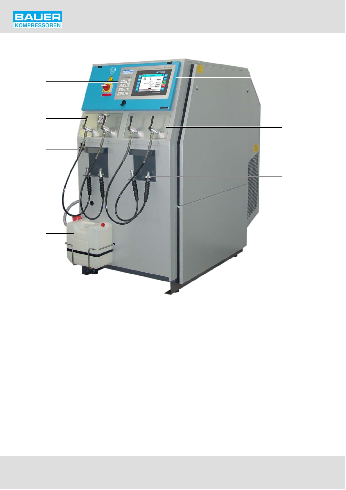
Fig. 1 Compressor unit, V series Super-Silent; front view, condensate collector fitted
1 Main switch
2 Filling valve 300 bar
3 Scavenging valve
4 Condensate collector, 10 ltrs.
5 Compressor control unit
6 Filling panel 300 bar
7 Bottle connector 300 bar
Table of contents
Other Bauer Kompressoren Air Compressor manuals


Popular Air Compressor manuals by other brands

NARDI COMPRESSORI
NARDI COMPRESSORI Diving Hookah Operation and maintenance manual

Clarke
Clarke XE36/C200 Operation & maintenance instructions

DeWalt
DeWalt XR FLEX VOLT DCC1054 manual

DeWalt
DeWalt D55167 instruction manual

MAT Industries
MAT Industries Speedaire C151G operating instructions

Protocol
Protocol 250 PSI instruction manual


