Bauer Kompressoren B-SAFE 300 Guide
Operating manual and
Spare parts list
Fail-safe Filling Ramp


Operating Manual wB-SAFE 300
i
INTRODUCTION
This manual contains information and instructions for the service
and maintenance of the following type of fail-safe filling ramps:
In order to avoid damage or premature wear and tear of the
machine, strictly follow the prescribed operating instructions.
The defects and damages caused by the failure to follow these
instructions are not covered by the guarantee.
WARNING
! Pneumatic high pressure system !
Edition January 2012
W2012 BAUER Kompressoren GmbH, München
All rights reserved.
B-SAFE 300

Operating Manual wB-SAFE 300
ii
TABLE OF CONTENTS
1. DESCRIPTION 1................................................................................
2. COMPOSITION 1...............................................................................
2.1. FILLING CHAMBER 1..............................................................................
2.2. FILLING ACCESSORIES 2...........................................................................
2.3. PROPORTIONAL/SOLENOID VALVE 2.................................................................
2.4. AUTOMATIC DEPRESSURISATION SYSTEM 2...........................................................
2.5. EMERGENCY STOP 2.............................................................................
2.6. ELECTRONIC CONTROL FOR FILLING 2...............................................................
3. OPERATING PRINCIPLE 10........................................................................
3.1. B-SAFE 300 WITH PROPORTIONAL VALVE, 10..........................................................
3.2. B-SAFE 300 WITH SOLENOID VALVE AND TWO PRESSURE RANGES 11......................................
4. TECHNICAL CHARACTERISTICS 12.................................................................
5. INSTALLATION 13...............................................................................
5.1. INSTALLATION ROOM 13...........................................................................
5.2. FITTING 13......................................................................................
5.3. CONNECTIONS 13.................................................................................
5.4. SECURE FILLING STATION, MODEL 14.................................................................
6. SAFETY MEASURES 15...........................................................................
6.1. WARNING NOTICES AND SIGNS 15...................................................................
6.2. SIGNS FOR SAFETY INSTRUCTIONS 15.................................................................
6.3. BASIC SAFETY INSTRUCTIONS 15.....................................................................
6.4. SAFETY REGULATIONS (VALID IN FRANCE) 16..........................................................
7. ACTIVATION/OPERATION 19......................................................................
7.1. ACTIVATION 19..................................................................................
7.2. FILLING 19......................................................................................
7.3. USING THE TRACEABILITY OPTION 21.................................................................
8. MAINTENANCE 23...............................................................................
8.1. PROOF OF MAINTENANCE 23.......................................................................
8.2. INSTRUCTIONS 23.................................................................................
8.3. MAINTENANCE WORKS 23.........................................................................
9. TRANSPORT 23..................................................................................
10. STORAGE 23....................................................................................
11. ANNEXE 25.....................................................................................
11.1. QUICK START 25..................................................................................
11.2. PROGRAMME STRUCTURE 26.......................................................................
11.3. PROGRAMME STRUCTURE – TRACEABILITY 27..........................................................
11.4. LISTS 29........................................................................................
11.5. PNEUMATIC DIAGRAMS 31.........................................................................
11.6. WIRING DIAGRAM 35..............................................................................

Operating Manual wB-SAFE 300
iii
TABLE OF FIGURES
Fig. 1 B-SAFE 300 with integrated filling ramp (optional) 1....................................................
Fig. 2 Screen 2.......................................................................................
Fig. 3 Navigation keys 3................................................................................
Fig. 4 Main page 3....................................................................................
Fig. 5 Main page: filling not allowed (1/2) 3................................................................
Fig. 6 Main page: filling not allowed (2/2) 3................................................................
Fig. 8 MAINTENANCE page 4............................................................................
Fig. 9 PASSWORD page 4...............................................................................
Fig. 10 Alphanumeric keyboard 5.........................................................................
Fig. 11 SETTINGS page 5................................................................................
Fig. 12 ACTIVE ALARM LIST page 6........................................................................
Fig. 13 Alarms HISTORY page 6...........................................................................
Fig. 14 Main page – traceability 7.........................................................................
Fig. 15 PASSWORD page – traceability 7....................................................................
Fig. 16 LOGIN CHANGE page – traceability 7................................................................
Fig. 17 SETTINGS page – traceability 8.....................................................................
Fig. 18 SCAN CYLINDERS page 8..........................................................................
Fig. 19 SCAN CYLINDERS – EXAMPLE page 8................................................................
Fig. 20 2D code reader 8................................................................................
Fig. 21 ACTIVE ALARM LIST page 9........................................................................
Fig. 22 LAST FILLING page 9.............................................................................
Fig. 23 Pneumatic diagram, B-SAFE 300 with proportional valve and 2 pressure ranges. 10............................
Fig. 24 Pneumatic diagram, B-SAFE 300 with solenoid valve and two pressure ranges. 11.............................
Fig. 25 Dimensions (in mm) 12.............................................................................
Fig. 26 Minimum distances and hazardous areas 13............................................................
Fig. 27 Secure filling station 14............................................................................
Fig. 28 Control panel 19..................................................................................
Fig. 29 Connecting the compressed air cylinders 20............................................................
Fig. 30 International fitting 20.............................................................................
Fig. 31 Filling the compressed air cylinders 20................................................................
Fig. 32 Removing the compressed air cylinders 21.............................................................
Fig. 33 2D code reader 21................................................................................
Fig. 34 Scanned labels _ example 21........................................................................

Operating Manual wB-SAFE 300
iv
INDEX
A
Activation, 19
Alarms, 6
Annexe, 25
Automatic depressurisation, 2
C
Connections, 13
D
Dimensions (in mm), 12
E
Electronic control, 2
Active alarm list, 6
History, 6
Last filling page, 9
Machine references, 4
Main page, 3
Maintenance page , 4
Password, 4
Settings, 5
Emergency stop, 2
F
Filling, 19
Filling accessories, 2
Filling chamber, 1
Fillingvalves, 2
Fitting, 13
H
Hazardous areas, 13
History, 6
I
Installation, 13
L
Labels, 8
Lists, 29
Alarms, 29
Filling statuses, 29
Messages on the bottom of the screen, 29
Save example, 29
M
Maintenance, 4, 23
Flexible hoses for filling, 23
Maintenance works, 23
Proof of maintenance, 23
Regulator, 23
Safety valves, 23
Minimum distances, 13
O
Operation, 10
P
Pneumatic diagram, 10, 11
Pneumatic diagrams, 31
Proportional valve, 2
Q
Quick start, 25
R
Regulation, 16

Operating Manual wB-SAFE 300
v
INDEX
S
Safety, 15
Save, 22
Scanner, 8
Secure filling station, 14
Settings, 5
Traceability option, 8
Solenoid valve, 2
Start-up, 19
Storage, 23
T
Technical characteristics, 12
Traceability, 7
Filling the cylinders, 21
Login, 7
Settings, 8
Transport, 23
U
USB, 9
USB Key, 9
W
Wiring diagram, 35

Operating Manual wB-SAFE 300
vi
Diagrams: Code
Pneumatic diagram, B-SAFE with solenoid valve, flexible hoses and two pressure ranges ISP 0175-A
Pneumatic diagram, B-SAFE with solenoid valve for integrating a filling panel ISP 0176-A
Pneumatic diagram, B-SAFE with proportional valve, flexible hoses and two pressure ranges ISP 0173-A
Wiring diagram, B-SAFE with proportional valve for integrating a filling panel ISP 0174-A
Wiring diagram, B-SAFE ISE 0236
Spare parts catalogue: Code
B-SAFE 300 G71.2
Modification notice
The modifications with respect to the previous edition are shown to the right of a vertical line.
Modification no. Modification date
0January 2012, first edition
Operating Manual wB-SAFE 300
1
1. DESCRIPTION
The B-SAFE 300 fail-safe fill ramp can be used, with any type of
breathing air compressor, for the purpose of safe and controlled
filling of breathing air cylinders.
An enclosed filling chamber protects the operator from cylinder or
flexible hose explosions during the filling process. In addition,
electronic control allows precise configuration of the filling.
2. COMPOSITION
The B-SAFE 300 ramp consists of the following main components:
wExplosion-proof filling chamber
wFilling accessories
wProportional/solenoid valvea)
wAutomatic depressurisation system
wElectronic control for filling
2.1. FILLING CHAMBER
The body of the enclosed safety chamber, built using steel sheets,
is extremely stable:
wTwo explosion-proof sliding doors protect the filling chamber
where the cylinders are connected.
wThe automatic locking system of the doors prevents the doors
from opening during the filling of cylinders. At the same time,
it prevents the filling of cylinders while the doors are open.
wOpenings on the sides and top of the ramp allow a controlled
release of compressed air in case of an explosion of a cylinder or
a flexible hose.
Openings for handling are provided on all sides to facilitate the
transport.
1
2
4
5
7
6
8
9
512 13
14
11
10
6
3
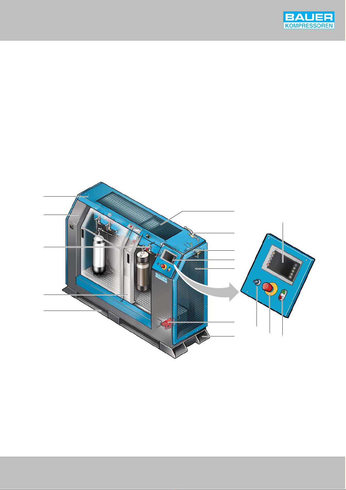
Fig. 1 B-SAFE 300 with integrated filling ramp (optional)
1 Body
2 Name plate
3 Filling valves
4 Sliding door
5 Openings for handling
6 Openings for air release
7 Manual inlet valve
8 Proportional valve
9 Control panel
10 Door locking system
11 Main switch
12 Emergency stop
13 On/Off switch with light indicator
14 Touch screen
a) Option
Operating Manual wB-SAFE 300
2
2.2. FILLING ACCESSORIES
In its standard configuration, the B-SAFE filling ramp is equipped
with flexible hoses and filling valves.
The B-SAFE ramp is available without any accessories or with an
integrated BAUER external filling ramp upon request. All the BAUER
external filling ramps that are available for the B-SAFE are equipped
with filling valves and direct filling valves.
The B-SAFE ramp is available with:
wpressure range (PN200 or PN300), or
wtwo pressure ranges (PN200 and PN300).
The second pressure range is obtained using a regulator which
allows you to fill two cylinders with different pressures
simultaneously.
The B-SAFE 300 ramp allows simultaneous filling of a maximum of:
w6 diving cylinders, or
w10 HP cylindersa) .
The number of connections must be determined according to the
output of the compressor as the time taken to fill the cylinders
depends on the latter.
2.3. PROPORTIONAL/SOLENOID VALVE
The B-SAFE filling ramp is available with:
wa proportional valve (can be used only with a storage bench), or
wa solenoid valve.
2.3.1. Proportional valve
The proportional valve helps regulate the speed used to fill the
cylinders between 20 and 50 bar/min. This reduced filling speed
limits the risk of explosion and wear and tear of the cylinders,
particularly of those made of composite materials.
The filling speed is adjusted using electronic controls. Refer to
Fig. 11, page 5.
2.3.2. Solenoid valve
The solenoid valve is used to open or isolate the internal pneumatic
circuit. Thus, it only allows direct filling of cylinders i.e. the time
required for filling depends directly on the output of the compressor.
2.4. AUTOMATIC DEPRESSURISATION SYSTEM
The B-SAFE ramp can be equipped with a depressurisation system
which automatically aerates the internal pneumatic circuit when
adoor is opened or emergency stop function is activated.
The compressed air in the cylinders does not escape into the
atmosphere during the depressurisation as the filling valves are
fitted with a non-return valve. In order to be able to disconnect the
cylinders with minimum risk, the valves are also provided with an air
valve that opens when the valve is loosened.
2.5. EMERGENCY STOP
In case of danger, it is possible to stop filling the cylinders
immediately by pressing the emergency switch (12, Fig. 1). It
interrupts the electric supply and:
wthe proportional valve or solenoid valve shuts down and the
internal pneumatic circuit is depressurised,
wthe doors remain locked,
wthe indicator light flashes and the message “Emergency stop” is
displayed at the bottom of the screen.
To restart the B-SAFE ramp, rotate the emergency switch (12, Fig. 1)
by a quarter turn to the left and then press the “0” key (13).
Theindicator light stops flashing and the message “EMERGENCY
STOP” disappears from the screen. The filling of cylinders can start
again.
2.6. ELECTRONIC CONTROL FOR FILLING
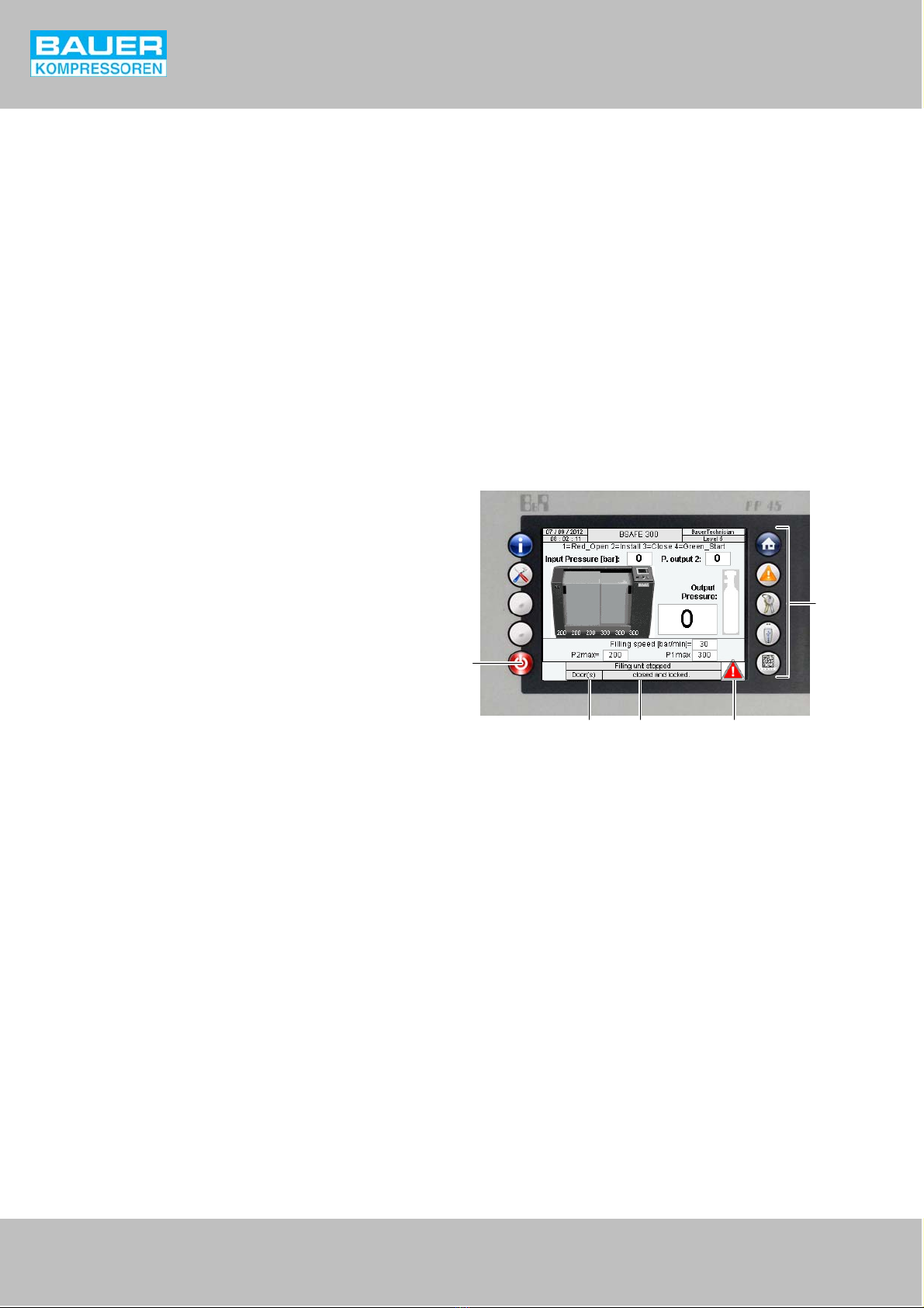
The electronic control system has a 6-inch touch screen (Fig. 2) for
displaying and regulating filling parameters.
Fig. 2 Screen
5
1
23 4
1 Stand by button
2 Double status bar
3 Touch screen
4 Alarm indication
5 Navigation keys
2.6.1. Communication with the compressor
The electronic control system of the B-SAFE ramp can be connected
to that of the compressor. This allows remote start or shut down of
the compressor (only possible with direct filling i.e. without storage
or proportional valves).
In addition, the B-SAFE control panel can display a compressor
breakdown message. In such a case, the Alarm sign is displayed and
the message “Cycle interrupted: Comp. error” is displayed to
indicate that the compressor has shut down. The filling process is
stopped. After the repair work, the error must be acknowledged by
pressing the red button “0”. The flashing stops and the error
message disappears. The filling process can start again.
a) Only if combined with the standard filling accessories (maximum diameter of cylinders = 18 cm, maximum height = 60 cm)
Alarms
Settings
Machine
references
Password
ON-OFF and
Logout
Main
page
Export
files
Scanner
Option:
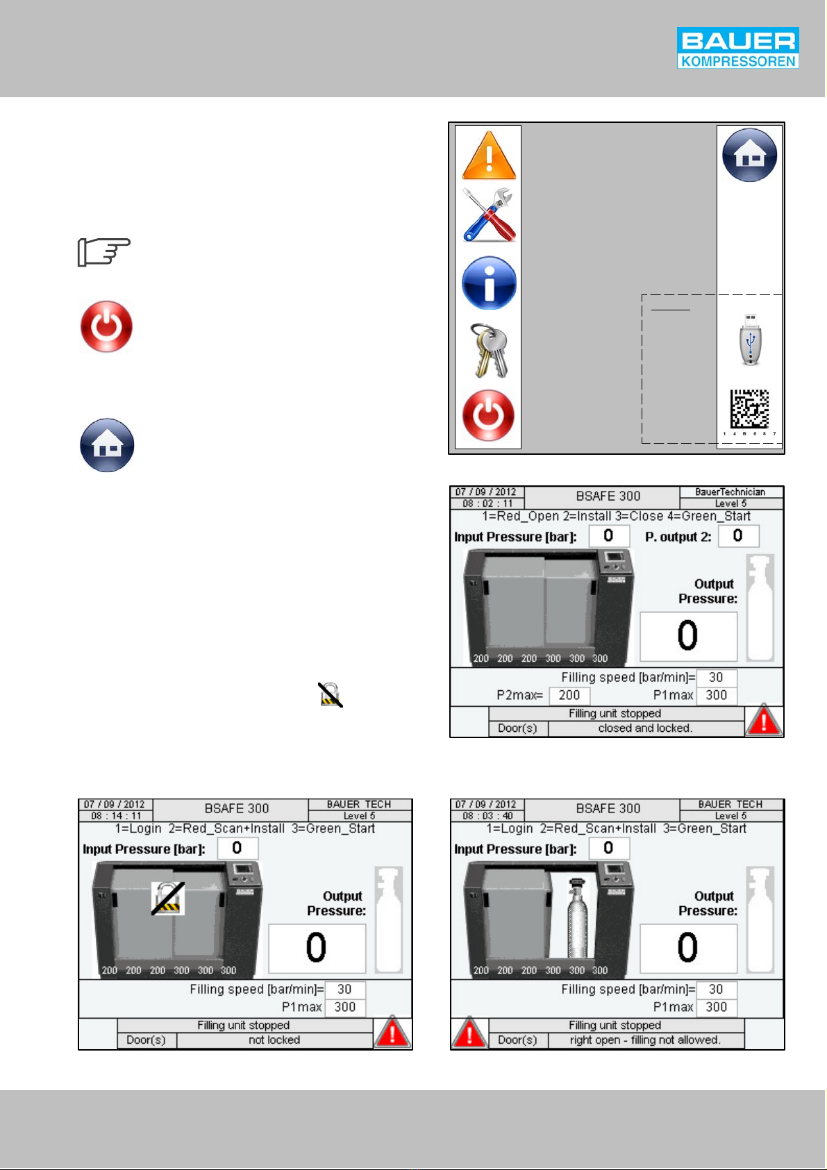
Fig. 3 Navigation keys
Fig. 4 Main page
Operating Manual wB-SAFE 300
3
2.6.2. Navigation
The electronic control panel has 6 to 8 navigation keys (Fig. 3)
depending on the version installed; the “Export files” and “Scan”
keys are available only with the Traceability option (see page 8).
Also refer to chapters 11.2. “Program structure” and 11.3. “Program
structure – Traceability” provided in the annexe.
On the entire screen, the active fields (values, text,
arrows, buttons, etc.) are black and the inactive or
inaccessible fields are grey.
ON / OFF
Unlike other navigation keys, the function of the ON/OFF switch is
not to open a window but to switch on or switch off the screen and
exit the current access level.
Main page
The main page (Fig. 4) comprising the basic information related to
the status of B-SAFE 300 ramp is displayed during every start-up.
This information includes the supply pressure (input pressure), filling
pressure(s) and filling speed (only for proportional valves) as well
asthe doors status.
– The output pressure (P1) is regulated through the software.
– The output pressure 2 (P2, option) is mechanically regulated
using a regulator.
Filling not allowed
In case the filling is not allowed the doors and locks can be regulated
from the main page. Example of Filling not allowed:
– Doors closed and unlocked – icon flashing (Fig. 5)
– Doors open – message at the bottom of the screen “Right open
- filling not allowed” (Fig. 6 )
Fig. 5 Main page: filling not allowed (1/2) Fig. 6 Main page: filling not allowed (2/2)
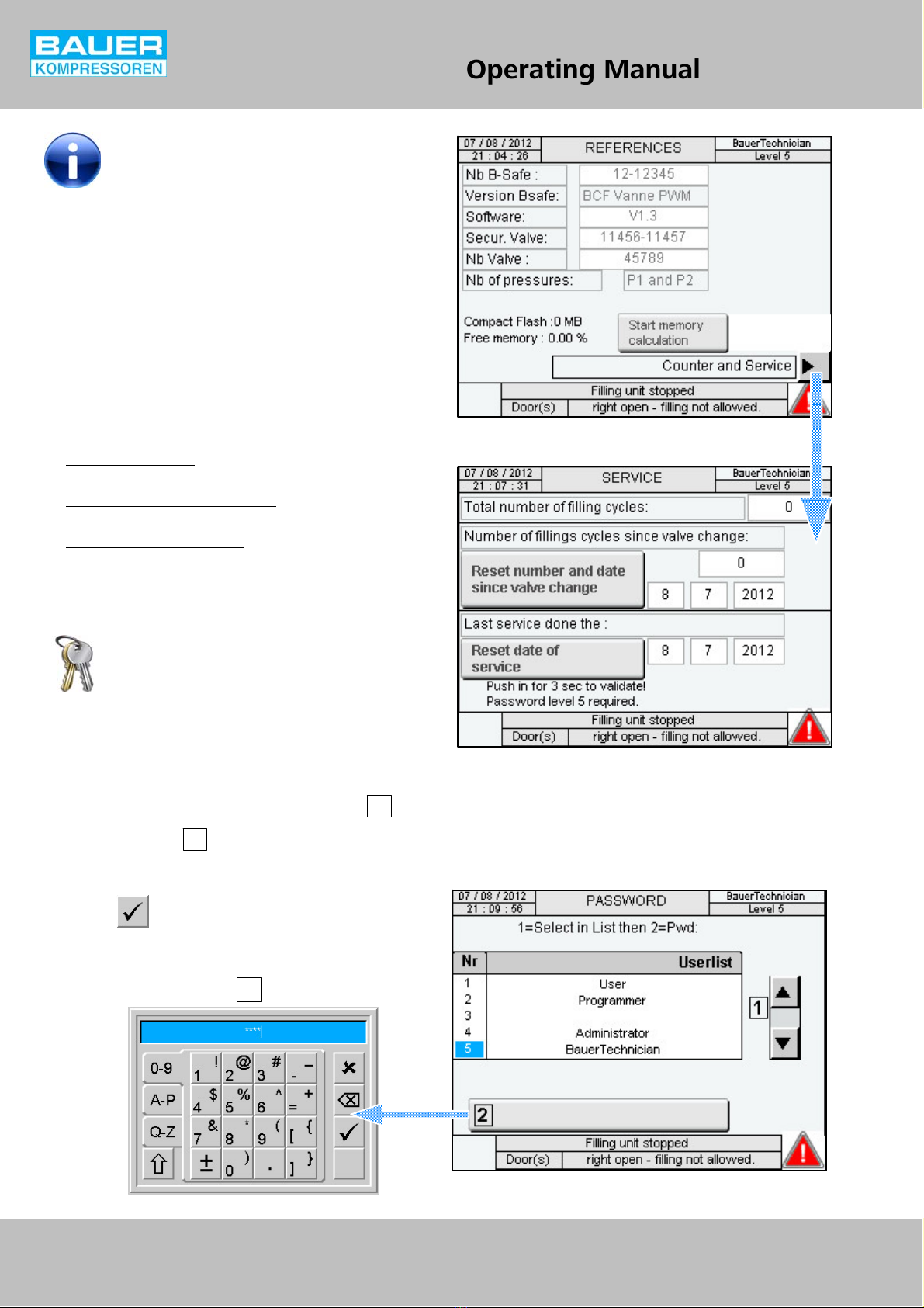
Fig. 7 MACHINE REFERENCES page
Fig. 8 MAINTENANCE page
TT
TT
TT
TT
TT
TT
TT
TT
Operating Manual wB-SAFE 300
4
MACHINE REFERENCES page
This page (Fig. 7) contains the information for quality control of the
BSAFE 300 and its main components.
Press the “Counters and Maintenance” arrow to open the
“Maintenance” page (Fig. 8). See below.
MAINTENANCE page
This page (Fig. 8) contains the counters and date of change of the
solenoid or proportional valve and the date of the last maintenance
work carried out:
wTotal number of cycles: counts the number of fillings since the
BSAFE 300 was activated.
wNumber of cycles since valve change: indicates the number of
fillings since the valve was replaced and the replacement date.
wLast maintenance carried out on: indicates the date on which the
last maintenance was carried out.
The counter-reset and modification of the maintenance date can be
done only by a SAV BAUER technician using a factory password (level
5 required).
PASSWORD page
To access certain functions of the automatic controller, the operator
must first open the corresponding access level (see “Password and
access levels”, page 5). The desired accesslevel is selected from the
password page (Fig. 9) and then opened by entering the
corresponding password :
–1 Selecting the level (1, 2, 4 or 5) using the arrows: 1
–2 Press the button: 2
–3 Enter the password corresponding to the level using
thealphanumeric keyboard present below and validate by
pressing .
Fig. 9 PASSWORD page
TTTTTT
TTTTTT
3
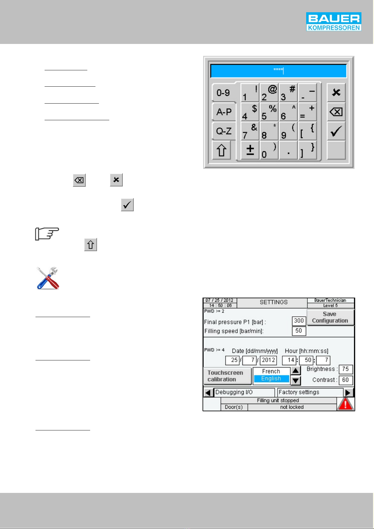
Fig. 10 Alphanumeric keyboard
Fig. 11 SETTINGS page
Operating Manual wB-SAFE 300
5
PASSWORD AND ACCESS LEVELS:
wLevel 1 “Operator”: default level,to carry out the filling process.
PWD (password) = “0”
wLevel 2 “Programmer”: to regulate the final pressure and filling
speed. PWD (password) = “1000”.
wLevel 4 “Administrator”: to regulate the screen settings. PWD
(password) = “0100”.
wLevel 5 “Factory settings”: access reserved for personnel
authorised by BAUER.
Entering the password
After selecting the desired level, an alphanumeric keyboard is
displayed on the screen (Fig. 10) where the access code can be
entered.
In case of a typing error, the last character can be deleted with the
help of the key . The key cancels the password entry
operation and returns to the “Password” screen.
After entering the password, press to access the selected
level.
The keyboard letters are useful only for the
TRACEABILITY function (AP and QZ). The
key can be used to enter symbols and
capital letters.
SETTINGS page (level 2, 4 and 5)
This page (Fig. 11) allows the operator to change the following
parameters:
Level 2 access required:
wFINAL PRESSURE P1: Select the value to change it.
wFILLING SPEEDa) : Select the value to change it. Enter the desired
speed (between 20 and 50 bar/min) using the keyboard
displayed on the screen.
Level 4 access required:
wDATE AND TIME: Select the value to change it.
wLANGUAGE: Select the desired language from the drop-down
menu.
wBRIGHTNESS AND CONTRAST OF THE SCREEN: Select the values
to change them.
wTOUCHSCREEN CALIBRATION: Select the targets in the order in
which they appear to re-align the touch detection.
Level 5 access required:
wI/O DEBUGGING and FACTORY SETTINGS: Access reserved for
personnel authorised by BAUER.
Once the modifications are complete, press “Save Configuration” to
save it.
a) Option available only with a proportional valve
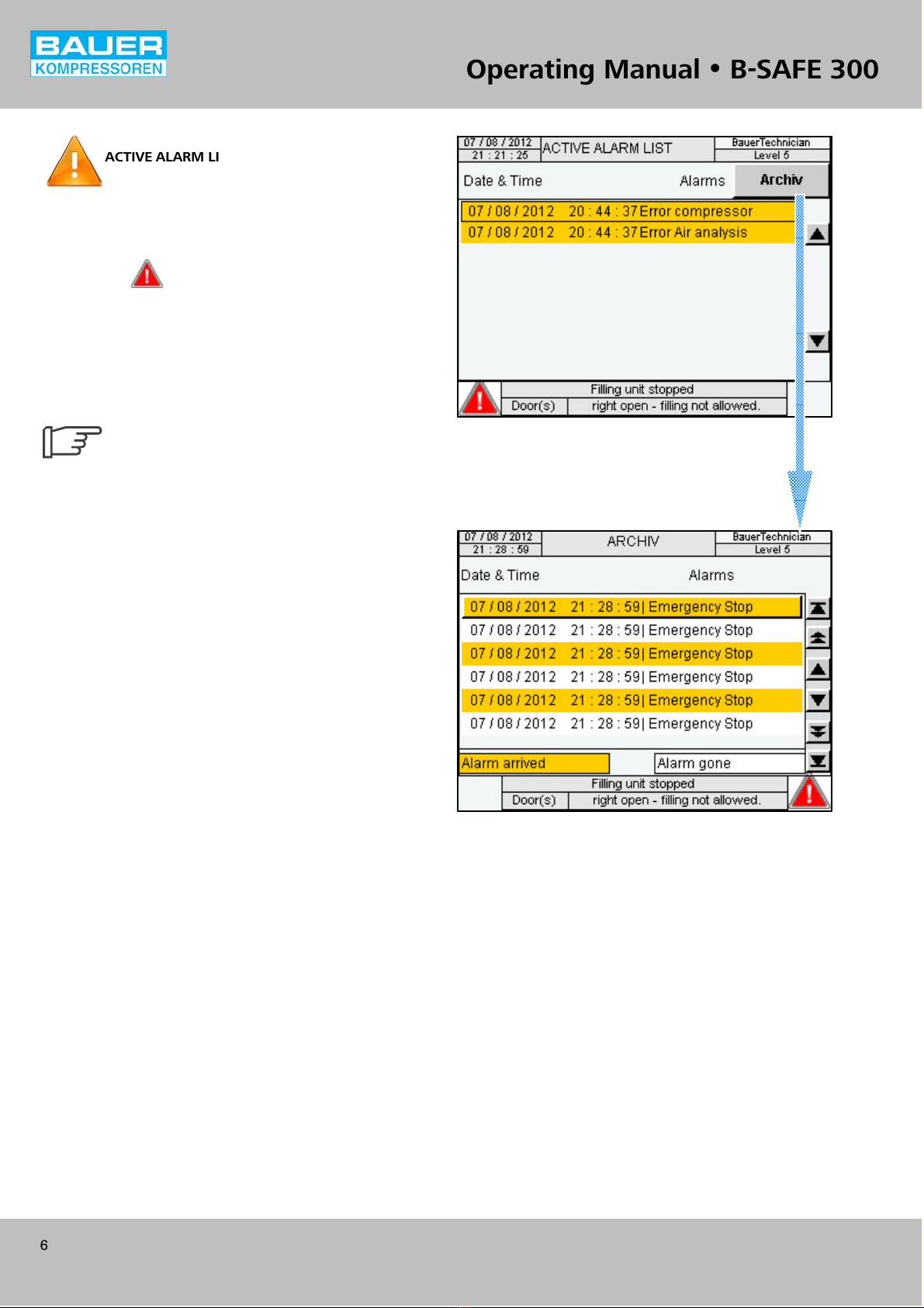
Fig. 12 ACTIVE ALARM LIST page
Fig. 13 Alarms HISTORY page
TTT
TTT
TTT
TTT
TTT
TTT
TTT
TTT
TTT
TTT
TTT
TTT
TTT
TTT
TTT
Operating Manual wB-SAFE 300
6
ACTIVE ALARM LIST page
This page (Fig. 12) allows the operator to view the active alarms of
the B-SAFE 300.
In case an alarm is active, the filling stops automatically and two
warning signs ( ) flash at the bottom of the screen.
Once the cause of activation of the alarm is identified and the
problem is resolved, all the alarms must be reset to return to normal
functioning. Press the red stop switch “0” (13, Fig. 1) to reset the
alarm and then press the green start switch “I” to restart the filling
of cylinders.
Also see the list of alarms in annexe, chap.11.4.3.
An alarm cannot be reset until the correspond
ing fault is repaired.
Press the “History” button to display the chronological list of alarms
(Fig. 13). See below.
HISTORY page
On the“HISTORY” page (Fig. 13), all the alarms displayed during the
operation of the ramp are automatically saved in a file of 1,000 lines.
Use the vertical arrows to scroll through the history. The bottom
arrow allows the user to view previous records.
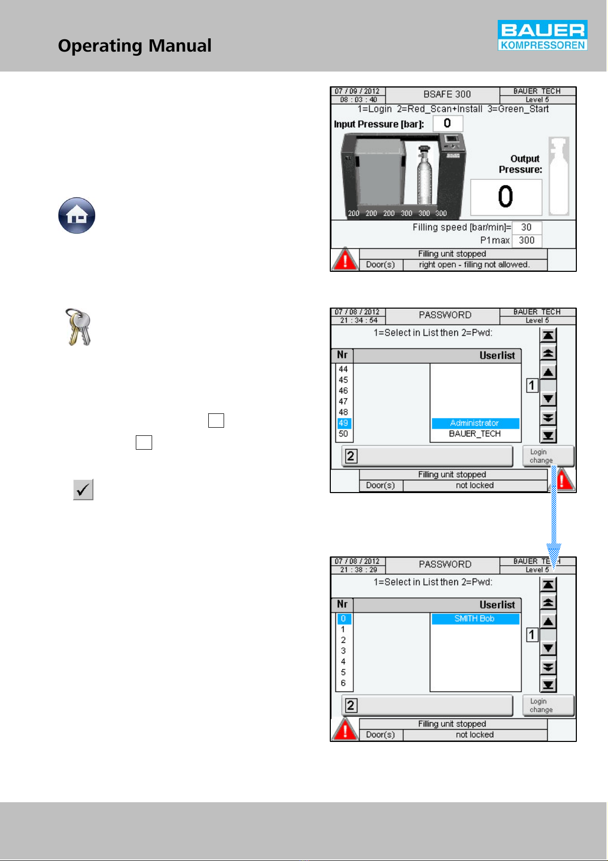
Fig. 14 Main page – traceability
Fig. 15 PASSWORD page – traceability
Fig. 16 LOGIN CHANGE page – traceability
TT
TT
TT
TT
TT
TT
TT
TT
Operating Manual wB-SAFE 300
7
TRACEABILITY OPTION
The traceability option allows a simple and effective check of the
cylinders. For this, the cylinders must have a label with a 2D code
containing the filling information of every cylinder. Once the label
is scanned, the B-SAFE 300 displays the characteristics of the
cylinders, thus allowing a quick check of the filling data. In addition,
after filling the cylinders, the B-SAFE 300 saves the filling parameters
of each cylinder. This data can then be saved on a USB key and
exported to an operating file.
Main page – traceability
If the BSAFE 300 is configured and has the option “TRACEABILITY”,
with the 2D code included, the main page is displayed as shown in
the image (Fig. 14).
To access the “Scan Cylinders” screen, the user must first identify
himself by accessing the “Password” screen. See below.
PASSWORD – LOGIN CHANGE page
On the machines that have the “TRACEABILITY” option, access to
the screens is limited, i.e., the operator must select the pre-saved
user that corresponds to him. It is the responsibility of the person in
charge of operating the station to save and manage the users, see
“Login change” below.
–1 Select the user using the arrows: 1, Fig. 15.
–2 Press the bar: 2.
–3 Enter the password corresponding to the level using the
alphanumeric keyboard present below and validate by pressing
.
User no. 50 is reserved for BAUER Compressor (level 5).
User Number 49 is pre-saved as Administrator in order to give the
operator in-charge access to login change. The operator in-charge
is advised to change and customise his password.
LOGIN CHANGE page
On this page (Fig. 16), the station administrator may:
– Create a user (name, password, level: min. 2)
– Change password
– Delete a user
– Logout: exit from the administrator level.
The station administrator can create 50 users (049) having different
levels: level 2 for a regular operator, level 3 for an operator
authorised to load the data on the USB key, level 4 for the station
administrator
Each user created must have a different password.
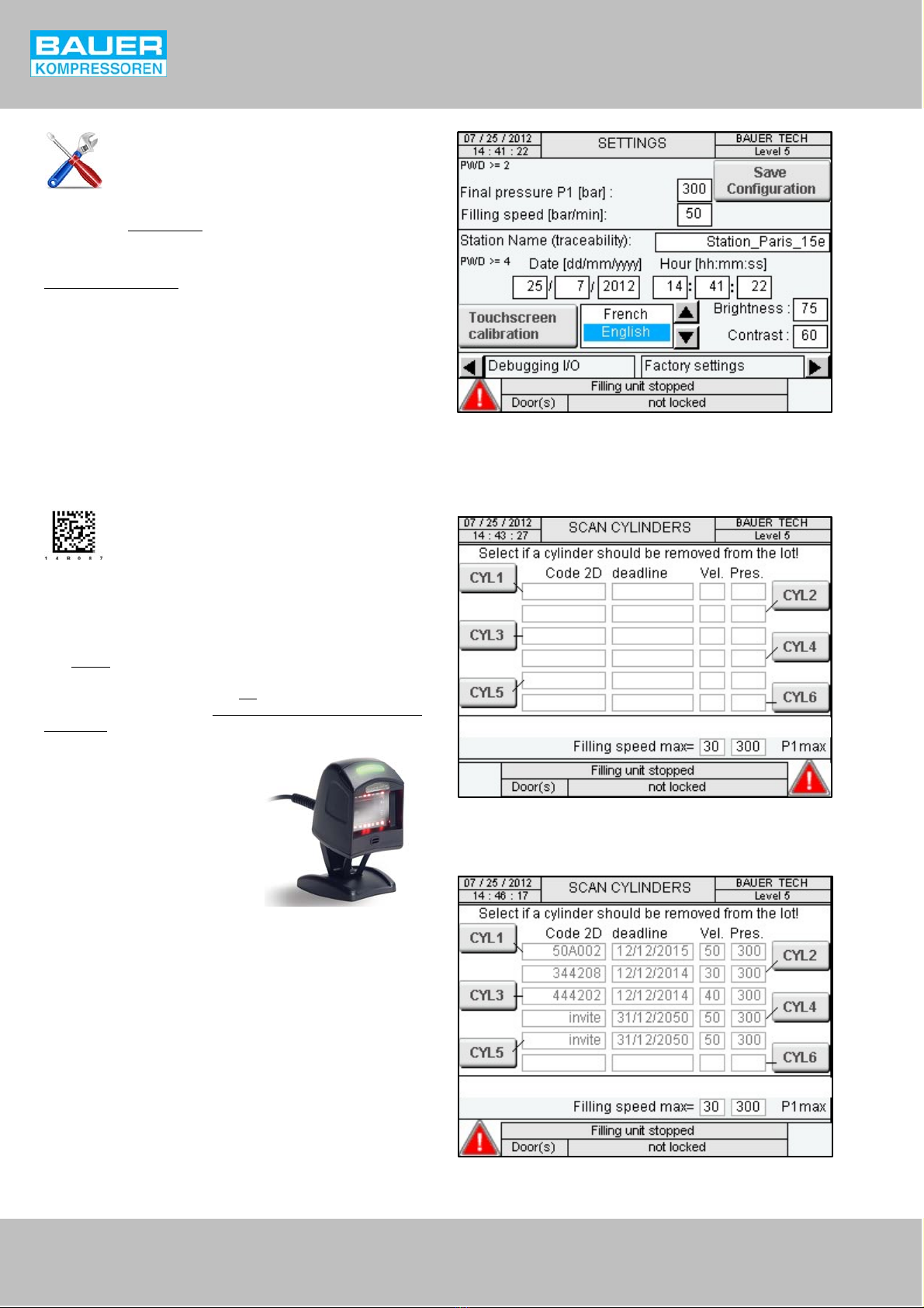
Fig. 17 SETTINGS page - traceability
Fig. 18 SCAN CYLINDERS page
Fig. 19 SCAN CYLINDERS – EXAMPLE page
Operating Manual wB-SAFE 300
8
SETTINGS page – traceability
With the traceability option, this page (Fig. 17) allows the operator
to change the station name as well as the pressure settings, filling
speed, date, time, brightness, contrast and realignment of the touch
detection (also see SETTINGS, page 5).
Level 4 access required:
– Station name (traceability): Press the box to enter the station
name using the alphanumeric keyboard, then press “Save
Configuration”.
SCAN CYLINDERS page
This page (Fig. 18) allows the operator to scan the cylinder labels in
order to save and check each cylinder before filling it.
In order to fill the values in the table, just scan the labels of the
cylinders that are to be filled using the 2D code reader.
If an ERROR message is displayed upon scanning a cylinder, it means
that the label was rejected due to inappropriate format or because
the expiry date has passed. Press OK to remove the message and
cancel the saving operation. Do not fill the cylinder and verify its
expiry date!
Fig. 20 2D code reader
SCAN CYLINDERS – EXAMPLE page
This page (Fig. 19) shows the results of the 5 cylinders in the B-SAFE
scanned before starting the secure filling.
Before starting the filling process, it is possible, to remove a scanned
cylinder. For this, press the corresponding CYLx button; the line is
thus erased.
w“Filling speed max” = the lowest filling speed authorised among
the scanned cylinders.
w“P1max” = final pressure set on the Settings page. The scanned
information related to the pressure of the cylinders is for
information purposes only.
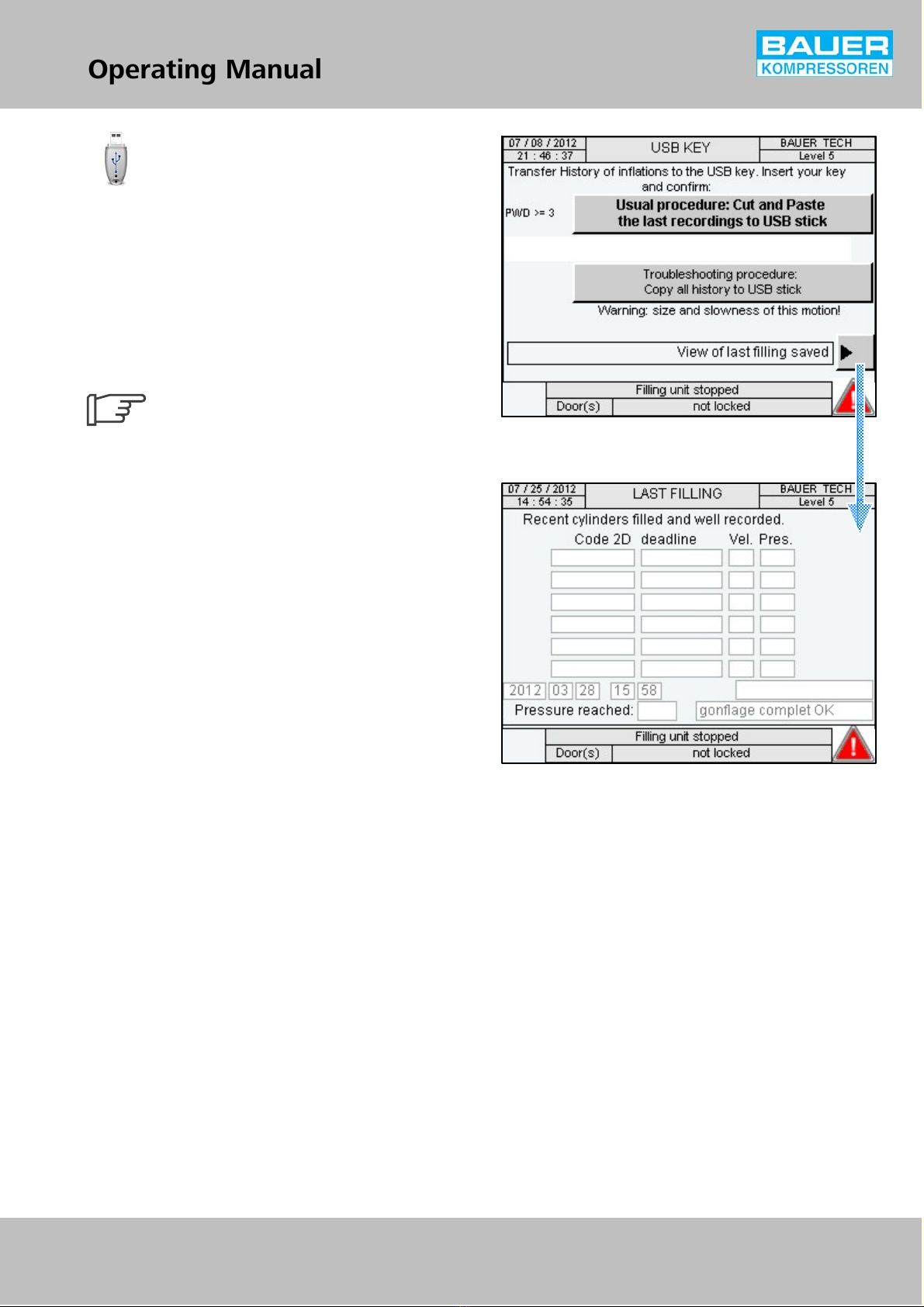
Fig. 21 ACTIVE ALARM LIST page
Fig. 22 LAST FILLING page
TT
TT
TT
TT
TT
TT
TT
TT
Operating Manual wB-SAFE 300
9
USB KEY page
This page (Fig. 21) allows the operator to transfer the following files
on a USB key:
– the history of the previous fillings by pressing the button: “Usual
procedure: Cut and Paste the last recordings to USB stick”,
– a backup of the entire history of the traceability since the BSAFE
300 was activated by pressing the button: “Troubleshooting
procedure: Copy all history to USB stick”
Only a registered user with the appropriate access level may carry
out this data transfer. See the “LOGIN CHANGE” page 7.
The USB port for inserting the key is located on
the top-right inside the B-SAFE 300.
Pressing the “View of last filling saved” arrow key displays the LAST
FILLING page (Fig. 22).
LAST FILLING page
The operator can view the last filling carried out once it is complete
and the doors are open. It remains open till the next filling.
Operating Manual wB-SAFE 300
10
3. OPERATING PRINCIPLE
The operating principle of the B-SAFE 300 ramp is described below
with the help of two examples:
wB-SAFE 300 with proportional valve and two pressure ranges,
wB-SAFE 300 with solenoid valve and two pressure ranges.
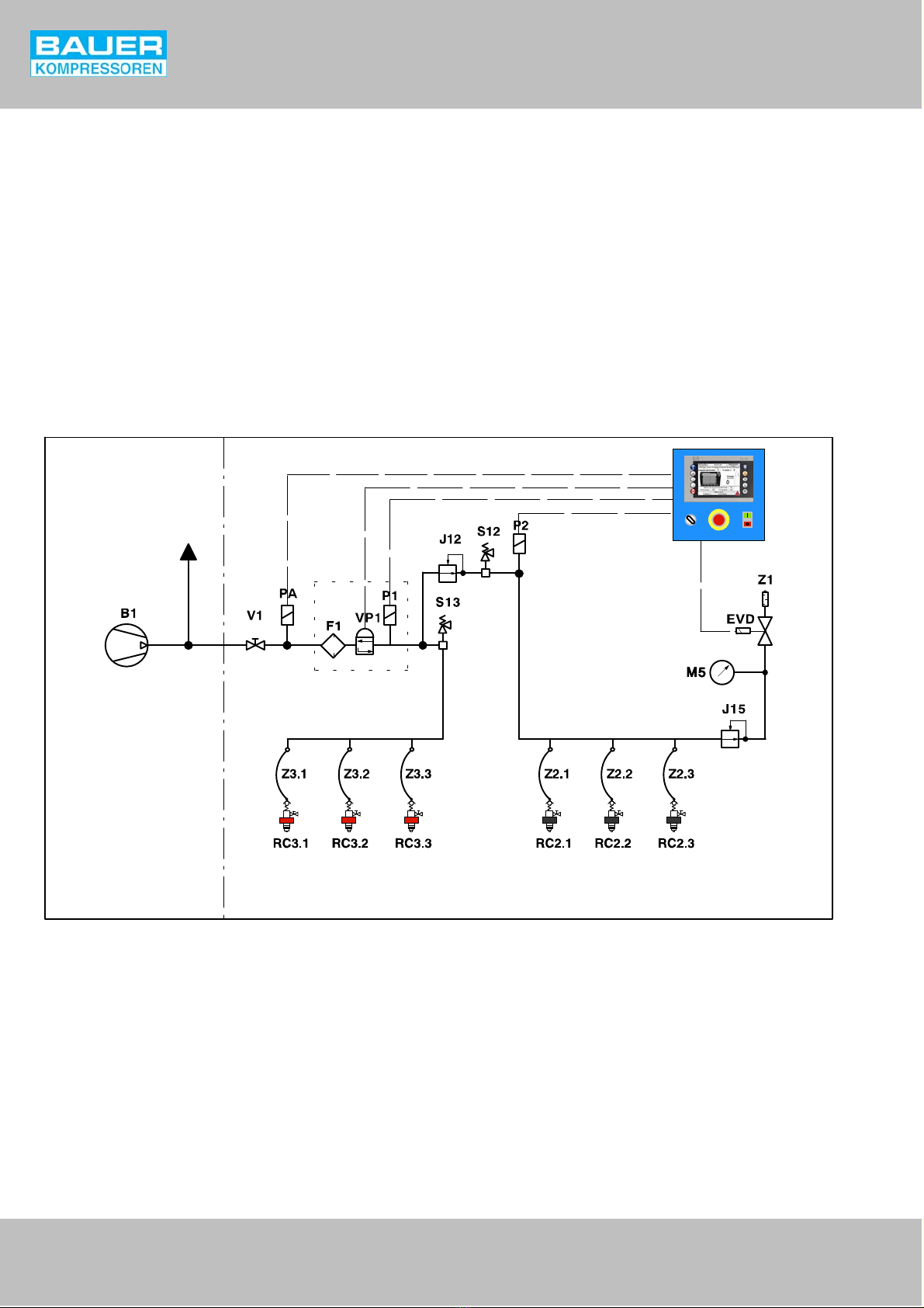
3.1. B-SAFE 300 WITH PROPORTIONAL VALVE,
The references indicated below refer to the positions of the
pneumatic diagram (Fig. 23).
The compressed air supplied by the compressor and storage enters
through the V1 manual shut-off valve.
The supply pressure and residual pressures of the cylinders are
measured by pressure sensors PA, P1 and P2 respectively. The
proportional valve F1-VP1 regulates the filling pressure according to
the values measured by the sensors. In addition, the proportional
valve opens and automatically isolates the internal pneumatic circuit
while starting and stopping the filling process.
The secondary pressure is obtained by reducing the primary pressure
with the help of the J12 regulator.
The primary and secondary pressures are pneumatically limited by
the S13 and S12 safety valves respectively.
The compressed air is transferred to the cylinders through flexible
hoses Z3 and Z2 and the filling valves RC3 and RC2.
The depressurisation system consists of J15 regulators, an EVD
solenoid valve and a Z1 silencer. The EVD solenoid valve opens
automatically when a door of the machine is open (or when the
emergency stop option is activated), thus depressurising the internal
pneumatic circuit.
COMPRESSOR B-SAFE 300
TO
STORAGE
Fig. 23 Pneumatic diagram, B-SAFE 300 with proportional valve and 2 pressure ranges.
B1 HP compressor
EVD Solenoid valve, depressurisation
F1-VP1 Proportional valve (VP1) with filter (F1)
J12 Regulator
J15 Regulator
M5 Pressure gauge, depressurisation
PA Pressure sensor, input
P1 Pressure sensor, primary filling pressure
P2 Pressure sensor, secondary filling pressure
RC2 Filling valves, secondary pressure
RC3 Filling valves, primary pressure
S12 Safety valve, secondary pressure
S13 Safety valve, primary pressure
V1 Manual inlet valve
Z1 Silencer
Z2 Flexible filling hoses, secondary pressure
Z3 Flexible filling hoses, primary pressure
Operating Manual wB-SAFE 300
11
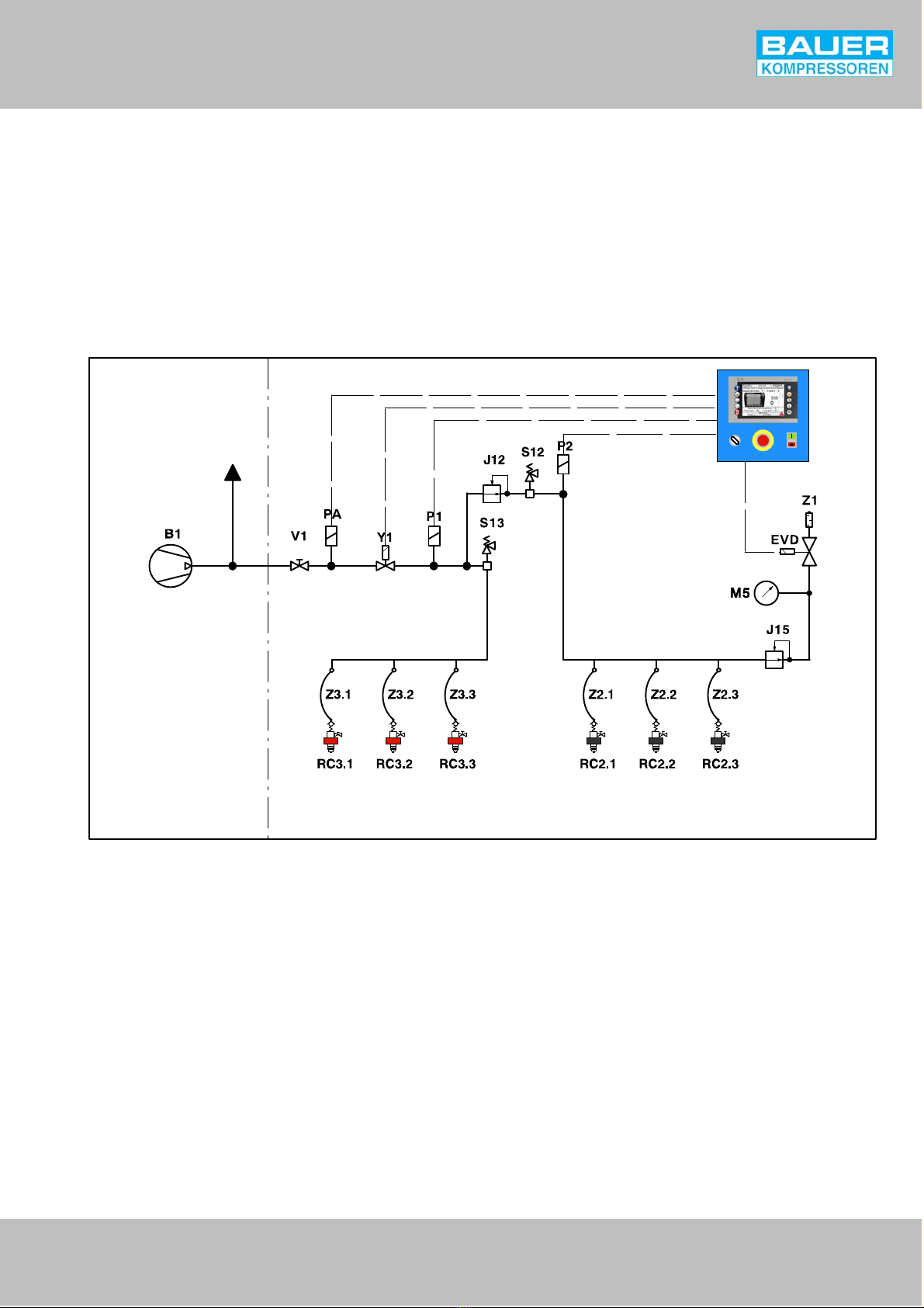
3.2. B-SAFE 300 WITH SOLENOID VALVE AND TWO
PRESSURE RANGES
The references indicated below refer to the positions of the
pneumatic diagram (Fig. 24).
The compressed air supplied by the compressor enters through the
V1 manual shut-off valve.
Compressed air directly enters (i.e. without being regulated) the
cylinders. The only function of the Y1 solenoid valve is to allow or
stop the supply of compressed air while starting or stopping the
filling process.
The secondary pressure is obtained by reducing the primary pressure
with the help of the J12 regulator.
The primary and secondary pressures are pneumatically limited by
the S13 and S12 safety valves respectively.
The compressed air is supplied to the cylinders through the flexible
hoses Z2 and Z3 and the filling valves RC2 and RC3.
The depressurisation system consists of J15 regulators, an EVD
solenoid valve and a Z1 silencer. The EVD solenoid valve opens
automatically when a door of the machine is open (or when the
emergency stop option is activated), thus depressurising the internal
pneumatic circuit.
COMPRESSOR B-SAFE 300
TO
STORAGE
Fig. 24 Pneumatic diagram, B-SAFE 300 with solenoid valve and two pressure ranges.
B1 HP compressor
EVD Solenoid valve, depressurisation
J12 Regulator
J15 Regulator
M5 Pressure gauge, depressurisation
PA Pressure sensor, entry
P1 Pressure sensor, primary filling pressure
P2 Pressure sensor, secondary filling pressure
RC2 Filling valves, secondary pressure
RC3 Filling valves, primary pressure
S12 Safety valve, secondary pressure
S13 Safety valve, primary pressure
V1 Manual inlet valve
Y1 Solenoid valve
Z1 Silencer
Z2 Flexible filling hoses, secondary pressure
Z3 Flexible filling hoses, secondary pressure
Operating Manual wB-SAFE 300
12
4. TECHNICAL CHARACTERISTICS
Fluid Breathable air in conformity with EN 12021........................................................................
Operating pressure Max. 410 bar.............................................................
Filling pressure (max. 2) PN200/PN300 bar.........................................................
Standard setting, final safety valve PN200 225 bar..........................................
Standard setting, final safety valve PN300 330 bar..........................................
Standard setting, final safety valve for operating with proportional valve 320 bar..................
Control range of the filling speed 20 to 50 bar/min.................................................
Number of filling items Max. 6 diving cylinders (max. 10 optiona) ).........................................................
Max. temperature permitted +5 to +45°C.....................................................
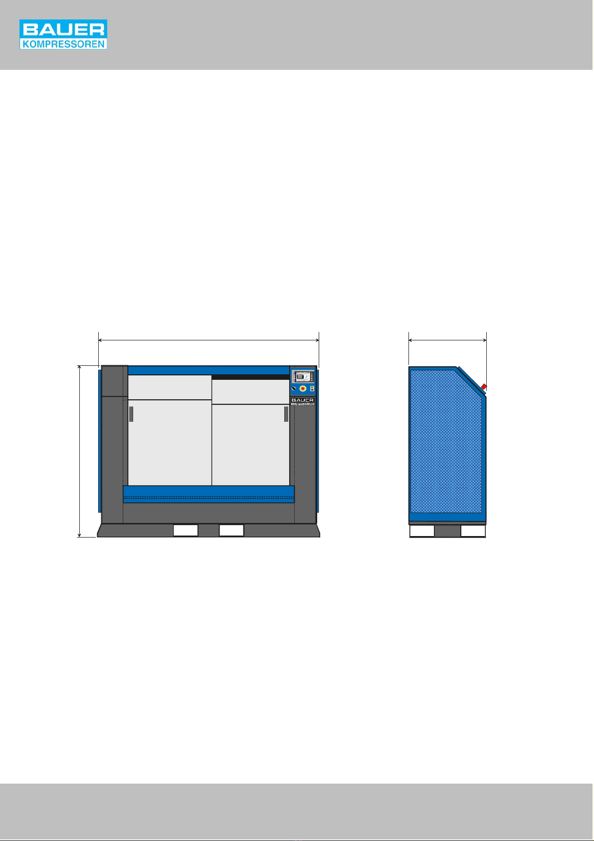
Dimensions See Fig. 25...................................................................
Internal dimensions of the filling chamber 1300 x 400 x 700 mm..........................................
Weight (standard version) About 350 kg.......................................................
Supply voltage 240 V, 50 Hz................................................................
Power consumption 100 W............................................................
Inlet connector for the compressed air 8S.............................................
1750 600
1350
Fig. 25 Dimensions (in mm)
a) Only if combined with the standard filling accessories (max diameter of cylinders = 18 cm, max height = 60 cm)
Table of contents
Popular Industrial Equipment manuals by other brands


PPI
PPI FLOREX Operation manual

Afag
Afag PEL20 Assembly and operating instructions

Festo
Festo EAMM-U Series Assembly instructions

Pepperl+Fuchs
Pepperl+Fuchs 6500 Series instruction manual

Vantage Hearth
Vantage Hearth Hollister-Whitney GLV-40D2 instruction manual

COREMO OCMEA
COREMO OCMEA D-M User and maintenance manual


