manuals.online logo
Brands
  1. Home
  2. •
  3. Brands
  4. •
  5. Festo
  6. •
  7. Industrial Equipment
  8. •
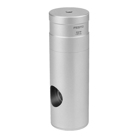
  9. Festo EAMM-U Series User manual

Festo EAMM-U Series User manual

This manual suits for next models

4

Other Festo Industrial Equipment manuals

Festo 152962 User manual

Festo

Festo 152962 User manual

Festo DFPI ND2P-C1V A Series User manual

Festo

Festo DFPI ND2P-C1V A Series User manual

Festo EAMM-U-50-S38-40A Assembly instructions

Festo

Festo EAMM-U-50-S38-40A Assembly instructions

Festo ELGA-TB-G User manual

Festo

Festo ELGA-TB-G User manual

Festo CTEU-EC Operating and installation instructions

Festo

Festo CTEU-EC Operating and installation instructions

Festo Pick&Place Station User manual

Festo

Festo Pick&Place Station User manual

Festo MPS 8059892 Service manual

Festo

Festo MPS 8059892 Service manual

Festo EXCH-40-...-W Series User manual

Festo

Festo EXCH-40-...-W Series User manual

Festo KSK Series User manual

Festo

Festo KSK Series User manual

Festo VABM-B10-25EEE User manual

Festo

Festo VABM-B10-25EEE User manual

Festo EGC FA Series User manual

Festo

Festo EGC FA Series User manual

Festo EPCC-BS-KF User manual

Festo

Festo EPCC-BS-KF User manual

Festo VTSA Series User manual

Festo

Festo VTSA Series User manual

Festo VABM-C8-12E-N14 Series User manual

Festo

Festo VABM-C8-12E-N14 Series User manual

Festo VABD Series User manual

Festo

Festo VABD Series User manual

Festo CP-FB5-E Parts list manual

Festo

Festo CP-FB5-E Parts list manual

Festo SPC11 Series Operating and installation instructions

Festo

Festo SPC11 Series Operating and installation instructions

Festo ELCC-TB-KF-60 F1 Series Setup guide

Festo

Festo ELCC-TB-KF-60 F1 Series Setup guide

Festo DHTG-***-P4 User manual

Festo

Festo DHTG-***-P4 User manual

Festo VABM-B10-30EEE User manual

Festo

Festo VABM-B10-30EEE User manual

Festo CPX-ST-1 User manual

Festo

Festo CPX-ST-1 User manual

Festo EPCE-TB User manual

Festo

Festo EPCE-TB User manual

Festo HGPPI Series User manual

Festo

Festo HGPPI Series User manual

Festo DNCB Setup guide

Festo

Festo DNCB Setup guide

Popular Industrial Equipment manuals by other brands

ABB +Q957 user manual

ABB

ABB +Q957 user manual

G.B.C BASIC EDGE 50 instruction manual

G.B.C

G.B.C BASIC EDGE 50 instruction manual

Tronair Batpak 11-6602-1000 Operation & service manual

Tronair

Tronair Batpak 11-6602-1000 Operation & service manual

Pilz PNOZ mi2p Operation manual

Pilz

Pilz PNOZ mi2p Operation manual

Clemco Zero BNP 6012 manual

Clemco

Clemco Zero BNP 6012 manual

Erskine Attachments V-Plow Operator's manual

Erskine Attachments

Erskine Attachments V-Plow Operator's manual

ABB HT610965 Operation manual

ABB

ABB HT610965 Operation manual

Morra MH 540 user manual

Morra

Morra MH 540 user manual

Eaton S090ST manual

Eaton

Eaton S090ST manual

GRIGGIO G 240 P4 instructions

GRIGGIO

GRIGGIO G 240 P4 instructions

Nexen AIR CHAMP HT45 user manual

Nexen

Nexen AIR CHAMP HT45 user manual

WTE V5 installation manual

WTE

WTE V5 installation manual

ABB HT845232 Operation manual

ABB

ABB HT845232 Operation manual

SMC Networks CJP Series Operation manual

SMC Networks

SMC Networks CJP Series Operation manual

JohnDow Industries JDI-AFT58 Operator's manual

JohnDow Industries

JohnDow Industries JDI-AFT58 Operator's manual

IMB MB9016A instruction manual

IMB

IMB MB9016A instruction manual

Clarke CUMB1 Assembly & operating instructions

Clarke

Clarke CUMB1 Assembly & operating instructions

amiad Arkal Spin Klin 2 user guide

amiad

amiad Arkal Spin Klin 2 user guide

manuals.online logo
manuals.online logoBrands
  • About & Mission
  • Contact us
  • Privacy Policy
  • Terms and Conditions

Copyright 2025 Manuals.Online. All Rights Reserved.

EAMM-U-...-T...-...A/P/R-2
Parallel kit
Festo SE & Co. KG
Ruiter Straße 82
73734 Esslingen
Deutschland
+49 711 347-0
www.festo.com
Assembly instructions
8133030
2021-08c
[8133032]
Translation of the original instructions
© 2021 all rights reserved to Festo SE & Co. KG
1Applicable documents
All available documents for the product è www.festo.com/sp.
Observe further applicable documents:
–Operating instructions, motor
–Operating instructions, axis
2 Safety
2.1 Safety instructions
–Only mount the product on components that are in a condition to be safely
operated.
–Clean the shafts. The coupling hub [17] will grip without slipping only on a drive
shaft which is dry and free of grease.
–Maintain the alignment of the coupling hub [17].
–If the motor is loosened or turned, homing must be carried out on the axis.
–Select required mounting components. The kit contains all the mounting com-
ponents that may be required.
–Observe tightening torques. Unless otherwise specified, the tolerance is
± 20 %.
2.2 Intended use
2.2.1 Use
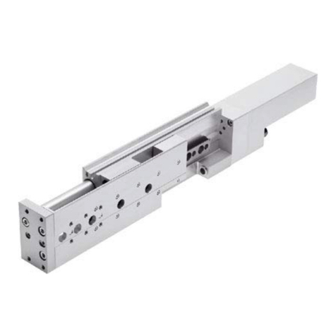
The parallel kit connects an axis to a motor in a parallel configuration.
2.2.2 Permissible axes and motors
NOTICE
Overloading can cause malfunction and material damage.
The motor’s output variables must not exceed the permissible values of the
components used.
Permissible values è www.festo.com/catalogue.
• Limit the motor’s output variables accordingly.
•Derive the axis and motor from the interface codes.
Example: EAMM-U-...-T42-60P
T42: axis interface
60P: motor interface
Axis interface Axis1)
T42 EGSC-BS-60, ELGC-BS-60, EPCC-BS-60
T46 ELGC-BS-80, ELGT-BS-90, ELGT-120, ELGT-160
1) Mini slide EGSC-BS, spindle axis ELGC-BS, spindle axis ELGT-BS, electric cylinder EPCC-BS
Tab. 1: Permissible axes
Motor interface Motor1)
57A EMCS-/EMMS-ST-57, third-party motor
60P EMMB-/EMME-/EMMT-AS-60, Fremdmotor
67A EMCA-EC-67
1) Servo motor EMM...-AS/third-party motor, stepper motor EMM...-ST/third-party motor, integrated drive
EMC...
Tab. 2: Permissible motors
It is the responsibility of users to qualify third-party motors with the matching
mechanical interface for the combination.
To find out which third-party motors are suitable, contact your regional Festo
contact or call è www.festo.com/sp.
2.3 Training of qualified personnel
Work on the product may only be carried out by qualified personnel who can eval-
uate the work and detect dangers. Personnel must have the relevant mechanical
training.
3 Additional Information
–Accessories è www.festo.com/catalogue.
4 Product Range Overview
4.1 Scope of delivery
1 2
5
6
7
8
9
10
15
16
17
18
19
20
Fig. 1: Basic scope of delivery
1Housing (1x)
2Screw (4x)
5Toothed belt (1x)
6Toothed belt pulley axis (1x)
7Cover (1x)
8Screw (3x)
9Square nut (4x)
10 Screw (4x)
15 Toothed belt pulley motor (1x)
16 Clamping screw (1x)
17 Coupling hub (1x)
18 Retaining ring (2x)
19 Elastomer star (2x)
20 Slip ring (2x)
The square nut [9] is not included with EAMM-U-...-67A.
40
41
Fig. 2: Addendum with EAMM-U-...-67A
40 Adapter plate (1x) 41 Screw (4x)
5 Assembly
5.1 Assembly
5.1.1 Preassembly of adapter plate (with EAMM-U-...-67A)
2
40
Fig. 3: Mount adapter plate
•Fasten the adapter plate [40] to the motor with the screws [2].
5.1.2 Preassembly of coupling
16
17 20
K
Fig. 4: Insert motor-side slip ring
1. Insert slip ring [20] into the slot [K] of the motor-side coupling hub [17].
2. Screw on locking screw [16].
17
C
Fig. 5: Push on the coupling hub, motor side
•Push coupling hub [17] with the matching drilled hole onto the drive shaft [C].
16
Fig. 6: Align coupling hub, motor side
1. Maintain distance (Y) è 5.1.3 Coupling alignment.
2. Tighten motor-side clamping screw [16].
20
L
P
Fig. 7: Insert slip ring axis side
•Insert slip ring [20] into the slot [L] of the axis-side coupling hub [P].
5.1.3 Coupling alignment
NOTICE
Faulty coupling alignment
If dimension Y is incorrectly adjusted, this will cause increased wear of the
toothed belt and may result in mechanical contact between the toothed belt
pulley and the housing or cover.
• Observe distance.
Adjusting dimension Y is measured on the flat face of the mounted adapter
plate [40] with EAMM-U-...-67A.
Fig. 8: Alignment of coupling hub
EAMM-U- Y±0.3
[mm]
65-T42-57A 18.8
65-T42-60P 19.8
65-T42-67A 19.8
87-T46-67A 19.3
Tab. 3: Dimension Y
5.1.4 Motor and axis connection
N
17
15
18
19
M
Fig. 9: Mount toothed belt pulley, motor side
1. Place elastomer spider [19] with recess [M] outwards in the toothed belt
pulley [15].
2. Push toothed belt pulley [15] with elastomer spider [19] onto the coupling
hub [17] to the stop.
3. Insert retaining ring [18] into the slot [N] of the coupling hub [17].
6
18
19
C
M
P
Fig. 10: Mount toothed belt pulley, axis-side
1. Place elastomer spider [19] with recess [M] outwards in the toothed belt
pulley [6].
2. Push toothed belt pulley [6] with elastomer spider [19] onto the coupling
hub [P] to the stop.
3. Insert retaining ring [18] into the slot [C] of the coupling hub [P].
1
10
Fig. 11: Mount housing on axis
• Mount housing [1] on the axis with the screws [10].
With EAMM-U
1
Fig. 12: Position motor - without adapter plate
• Position motor on housing [1].
ÄThe motor is movable and can be easily tilted.
With EAMM-U-...-67A
1
40
Fig. 13: Position motor - with adapter plate
• Position motor with adapter plate [40] on housing [1].
ÄThe motor is movable and can be easily tilted.
15
5
6
Fig.14
1. Move the motor in the direction of the axis up to the stop and tilt it slightly.
2. Place toothed belt [5] on the toothed belt pulley [15] first and then around the
toothed belt pulley [6].
With EAMM-U
1
2
9
Fig. 15: Attach motor - without adapter plate
•Attach the motor with the screws [2] and the square nuts [9] to the
housing [1].
ÄThe motor is movable, but it can no longer be tilted.
With EAMM-U-...-67A
40
41
1
Fig. 16: Attach motor - with adapter plate
•Attach housing [1] to the adapter plate [40] with the screws [41].
ÄThe motor is movable, but it can no longer be tilted.
5.1.5 Tensioning the toothed belt
NOTICE
Toothed belt pretensioning too high.
Impermissible radial loads or shaft break.
Increased wear of the toothed belt and the bearings of axis and motor.
•Avoid excessive toothed belt pretension.
A low toothed belt pretension is recommended.
The toothed belt [5] is tensioned when the strands [D] run approximately parallel:
–Untensioned: y > x
–Tensioned: y L 1 … 1.05 x
DD
Fig. 17: Strands of the toothed belt
2
5
Fig. 18: Tension toothed belt
1. Move the motor until the clamping force Fv is exerted on the toothed belt [5].
2. Tighten screws [2].
EAMM-U- Clamping force Fv
[N]
65 27 … 60
87 45 … 100
Tab. 4: Permissible clamping force of the toothed belt
5.1.6 Mounting the cover
1
7
8
Fig. 19: Mount cover
•Before commissioning: fasten cover[7] to the housing [8] with the screws [1].
5.2 Fitting
5.2.1 Supporting frame for the axis-motor combination
Fig. 20: Support the combination so it is free from tension
• Support the combination so it is free from tension to avoid damage.
6 In operation
CAUTION
Risk of injury from touching hot surfaces.
The motor connecting kit becomes hot due to the heat dissipation of the motor.
• Do not touch the motor connecting kit during operation or immediately after-
ward.
WARNING
Risk of injury due to unexpected movement of components if toothed belt fails.
• Take supplemental safeguarding measures.
7 Maintenance
7.1 Check the toothed belt
The toothed belt [5] is a wearing part è www.festo.com/spareparts.
1. Check toothed belt [5] regularly:
–during maintenance of the machine
–when replacing an axis
2. Replace the toothed belt [5] at the following indicators of wear:
–excessive accumulation of wear particles in the housing
–cracks on the back of the toothed belt
–visible glass fibre cords in the tooth base
7.2 Demounting the toothed belt
15
2
6
5
Fig.21
With vertical or diagonal mounting position of the axis:
• Observe applicable safety instructions in the instruction manual for the axis.
1. Remove screws [2].
ÄThe motor is movable and can be easily tilted.
2. Move the motor in the direction of the axis up to the stop and tilt it slightly.
3. Remove the toothed belt [5] from toothed belt pulleys [6] and [15].
8 Technical data
8.1 Screw sizes and tightening torques
EAMM-U- [2] [Nm] [8] [Nm] [10] [Nm] [16] [Nm]
65-T42-57A M5x12 6 M4x10 3 M4x10 3 M4x12 4
65-T42-60P M4x20 3 M4x10 3 M4x10 3 M4x12 4
65-T42-67A M6x10 10 M4x10 3 M4x10 3 M4x12 4
87-T46-67A M6x10 10 M5x12 6 M6x20 10 M4x12 4
Tab. 5
EAMM-U- [41] [Nm]
65-T42-67A M5x8 6
87-T46-67A M5x8 6
Tab. 6