Bauer 22202E-B Assembly instructions

NOTICE
FOR CEMENT AND
MORTAR ONLY.
Do not use with Epoxy
2-part resin mix.
Visit our website at: http://www.harborfreight.com
Owner’s Manual & Safety Instructions
Save This Manual Keep this manual for the safety warnings and precautions, assembly,
operating, inspection, maintenance and cleaning procedures. Write the product’s serial number in the
back of the manual (or month and year of purchase if product has no number). Keep this manual and the
receipt in a safe and dry place for future reference. 22j
When unpacking, make sure that the product is intact
and undamaged. If any parts are missing or broken,
please call 1-888-866-5797 as soon as possible.
Copyright©2022 by Harbor Freight Tools®. All rights reserved.
No portion of this manual or any artwork contained herein may be reproduced in
any shape or form without the express written consent of Harbor Freight Tools.
Diagrams within this manual may not be drawn proportionally. Due to continuing
improvements, actual product may differ slightly from the product described herein.
Tools required for assembly and service may not be included.
Read this material before using this product.
Failure to do so can result in serious injury.
SAVE THIS MANUAL.

Page 2 For technical questions, please call 1-888-866-5797. Item 58991
NOTICE
FOR CEMENT AND MORTAR ONLY.
Do not use with Epoxy 2-part resin mix.
SAFETY OPERATION MAINTENANCESETUP
NOTICE
FOR CEMENT AND MORTAR ONLY.
Do not use with Epoxy 2-part resin mix.
Table of Contents
Safety ......................................................... 2
Specifications ............................................. 7
Setup .......................................................... 2
Operation.................................................... 2
Maintenance............................................... 2
Parts List and Diagram.............................. 14
Warranty .................................................... 16
WARNING SYMBOLS AND DEFINITIONS
This is the safety alert symbol. It is used to alert you to potential
personal injury hazards. Obey all safety messages that
follow this symbol to avoid possible injury or death.
Indicates a hazardous situation which, if not avoided,
will result in death or serious injury.
Indicates a hazardous situation which, if not avoided,
could result in death or serious injury.
Indicates a hazardous situation which, if not avoided,
could result in minor or moderate injury.
Addresses practices not related to personal injury.
IMPORTANT SAFETY INFORMATION
WARNING Read all safety warnings and instructions. Failure to follow the warnings and instructions
may result in electric shock, fire and/or serious injury.
Save all warnings and instructions for future reference.
Assembly Precautions
1. Assemble only according to these instructions.
Improper assembly can create hazards.
2. Wear ANSI-approved safety goggles and
heavy-duty work gloves during assembly.
3. Keep assembly area clean and well lit.
4. Keep bystanders out of the area during assembly.
5. Do not assemble when tired or when under the
influence of alcohol, drugs or medication.
6. Weight capacity and other product capabilities apply
to properly and completely assembled product only.
Use Precautions
1. This product is not a toy. Do not allow
children to play with or near this item.
2. Use as intended only.
3. Inspect before every use; do not use
if parts are loose or damaged.
4. Do not exceed listed weight capacity.
Be aware of dynamic loading!
Sudden load movement may briefly create
excess load causing product failure.
5. DO NOT OVERLOAD MIXER. An
overload can damage equipment.
6. DO NOT MOVE MIXER DURING OPERATION.
The Mixer can tip over or motor could be damaged.
7. KEEP SAFE CLEARANCE AROUND MIXER.
Keep all persons (except operator) at least
six feet from Mixer during operation.
8. DON’T USE IN DANGEROUS ENVIRONMENT.
Don’t use power tools in damp or wet locations, or
expose them to rain. Keep work area well lighted.
9. KEEP CHILDREN AWAY. All visitors should
be kept safe distance from work area.
10. MAKE WORKSHOP KID PROOF with padlocks,
master switches, or by removing starter keys.

Page 3For technical questions, please call 1-888-866-5797.Item 58991
NOTICE
FOR CEMENT AND MORTAR ONLY.
Do not use with Epoxy 2-part resin mix.
SAFETYOPERATIONMAINTENANCE SETUP
NOTICE
FOR CEMENT AND MORTAR ONLY.
Do not use with Epoxy 2-part resin mix.
11. DON’T FORCE TOOL. It will do the job better
and safer at the rate for which it was designed.
12. USE RIGHT TOOL. Don’t force tool or attachment
to do a job for which it was not designed.
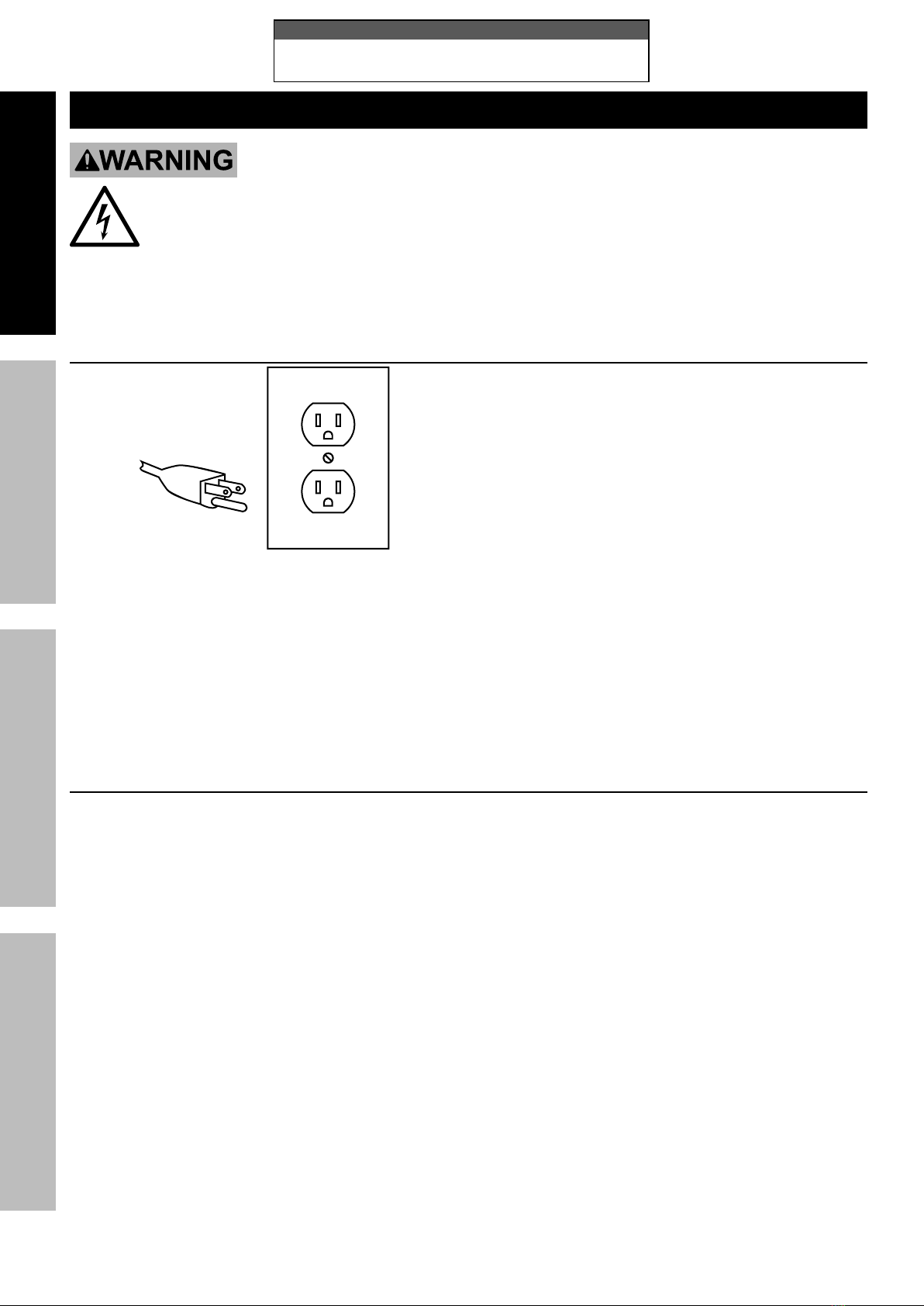
13. USE PROPER EXTENSION CORD. Make sure
your extension cord is in good condition. When
using an extension cord, be sure to use one
heavy enough to carry the current your product
will draw. An undersized cord will cause a drop
in line voltage resulting in loss of power and
overheating. Table A shows the correct size to use
depending on cord length and nameplate ampere
rating. If in doubt, use the next heavier gauge. The
smaller the gauge number, the heavier the cord.
14. WEAR PROPER APPAREL. Do not wear loose
clothing, gloves, neckties, rings, bracelets, or
other jewelry which may get caught in moving
parts. Nonslip footwear is recommended. Wear
protective hair covering to contain long hair.
15. SECURE WORK. Use clamps or a vise to hold
work when practical. It’s safer than using your
hand and it frees both hands to operate tool.
16. DON’T OVERREACH. Keep proper
footing and balance at all times.
17. MAINTAIN TOOLS WITH CARE. Keep
tools sharp and clean for best and safest
performance. Follow instructions for
lubricating and changing accessories.
18. DISCONNECT TOOLS before servicing;
when changing accessories, such as
blades, bits, cutters, and the like.
19. REDUCE THE RISK OF UNINTENTIONAL
STARTING. Make sure switch is in
off position before plugging in.
20. NEVER STAND ON TOOL. Serious injury
could occur if the tool is tipped or if the
cutting tool is unintentionally contacted.
21. NEVER LEAVE TOOL RUNNING
UNATTENDED. TURN POWER OFF. Don’t
leave tool until it comes to a complete stop.
22. Maintain product labels and nameplates.
These carry important safety information.
If unreadable or missing, contact
Harbor Freight Tools for a replacement.
Mixer Safety Warnings
1. FOR CEMENT AND MORTAR ONLY. DO NOT
USE WITH EPOXY 2-PART RESIN MIX.
2. Do not attempt to move the Cement Mixer
when it is full and/or in operation. It is unsafe
to move the mixer while in this condition, and
serious injury to personnel could occur.
3. When servicing use only identical replacement parts.
4. Only use safety equipment that has been approved
by an appropriate standards agency. Unapproved
safety equipment may not provide adequate
protection. Eye protection must be ANSI-approved
and breathing protection must be NIOSH-approved
for the specific hazards in the work area.
5. Industrial applications must follow OSHA guidelines.
6. Maintain labels and nameplates on
the tool. These carry important safety
information. If unreadable or missing, contact
Harbor Freight Tools for a replacement.
7. Avoid unintentional starting. Prepare to
begin work before turning on the tool.
8. People with pacemakers should consult their
physician(s) before use. Electromagnetic fields in
close proximity to heart pacemaker could cause
pacemaker interference or pacemaker failure.
9. The warnings, precautions, and instructions
discussed in this instruction manual cannot
cover all possible conditions and situations
that may occur. It must be understood by the
operator that common sense and caution are
factors which cannot be built into this product,
but must be supplied by the operator.

Page 4 For technical questions, please call 1-888-866-5797. Item 58991
NOTICE
FOR CEMENT AND MORTAR ONLY.
Do not use with Epoxy 2-part resin mix.
SAFETY OPERATION MAINTENANCESETUP
NOTICE
FOR CEMENT AND MORTAR ONLY.
Do not use with Epoxy 2-part resin mix.
Grounding
TO PREVENT ELECTRIC SHOCK AND DEATH FROM
INCORRECT GROUNDING WIRE CONNECTION:
Check with a qualified electrician if you are in doubt as to whether the outlet is properly
grounded. Do not modify the power cord plug provided with the tool. Never remove the
grounding prong from the plug. Do not use the tool if the power cord or plug is damaged. If damaged, have
it repaired by a service facility before use. If the plug will not fit the outlet, have a proper outlet installed by
a qualified electrician.
Grounded Tools: Tools with Three Prong Plugs
3-Prong Plug and Outlet
1. Tools marked with “Grounding Required” have
a three wire cord and three prong grounding
plug. The plug must be connected to a properly
grounded outlet. If the tool should electrically
malfunction or break down, grounding provides
a low resistance path to carry electricity away
from the user, reducing the risk of electric
shock. (See 3-Prong Plug and Outlet.)
2. The grounding prong in the plug is connected
through the green wire inside the cord to the
grounding system in the tool. The green wire
in the cord must be the only wire connected
to the tool’s grounding system and must
never be attached to an electrically “live”
terminal. (See 3-Prong Plug and Outlet.)
3. The tool must be plugged into an appropriate outlet,
properly installed and grounded in accordance
with all codes and ordinances. The plug and outlet
should look like those in the preceding illustration.
(See 3-Prong Plug and Outlet.)
Extension Cords
1. Grounded tools require a three wire extension cord.
Double Insulated tools can use either
a two or three wire extension cord.
2. As the distance from the supply outlet increases,
you must use a heavier gauge extension cord.
Using extension cords with inadequately sized wire
causes a serious drop in voltage, resulting in loss of
power and possible tool damage. (See Table A.)
3. The smaller the gauge number of the wire, the
greater the capacity of the cord. For example,
a 14 gauge cord can carry a higher current
than a 16 gauge cord. (See Table A.)
4. When using more than one extension cord
to make up the total length, make sure
each cord contains at least the minimum
wire size required. (See Table A.)
5. If you are using one extension cord for more
than one tool, add the nameplate amperes
and use the sum to determine the required
minimum cord size. (See Table A.)
6. If you are using an extension cord outdoors, make
sure it is marked with the suffix “W-A” (“W” in
Canada) to indicate it is acceptable for outdoor use.
7. Make sure the extension cord is properly wired
and in good electrical condition. Always replace
a damaged extension cord or have it repaired
by a qualified electrician before using it.
8. Protect the extension cords from sharp objects,
excessive heat, and damp or wet areas.

Page 5For technical questions, please call 1-888-866-5797.Item 58991
NOTICE
FOR CEMENT AND MORTAR ONLY.
Do not use with Epoxy 2-part resin mix.
SAFETYOPERATIONMAINTENANCE SETUP
NOTICE
FOR CEMENT AND MORTAR ONLY.
Do not use with Epoxy 2-part resin mix.
TABLE A: RECOMMENDED MINIMUM WIRE
GAUGE FOR EXTENSION CORDS* (120/240 VOLT)
NAMEPLATE
AMPERES
(at full load)
EXTENSION CORD
LENGTH
25´ 50´ 75´ 100´ 150´
0 – 2.0 18 18 18 18 16
2.1 – 3.4 18 18 18 16 14
3.5 – 5.0 18 18 16 14 12
5.1 – 7.0 18 16 14 12 12
7.1 – 12.0 18 14 12 10 -
12.1 – 16.0 14 12 10 - -
16.1 – 20.0 12 10 - - -
* Based on limiting the line voltage drop to five volts at
150% of the rated amperes.
Connecting Cords
To reduce the risk of the cords pulling apart
during operation, do one of the following:
a. Make a knot as shown below
then connect the cords:
b.
Extension
Cord
Appliance
Cord
1
2
Or, use a plug-receptacle retaining
strap or connector designed to hold
extension cords to appliance cords.

Page 6 For technical questions, please call 1-888-866-5797. Item 58991
NOTICE
FOR CEMENT AND MORTAR ONLY.
Do not use with Epoxy 2-part resin mix.
SAFETY OPERATION MAINTENANCESETUP
NOTICE
FOR CEMENT AND MORTAR ONLY.
Do not use with Epoxy 2-part resin mix.
Vibration Safety
This tool vibrates during use. Repeated or
long-term exposure to vibration may cause
temporary or permanent physical injury,
particularly to the hands, arms and shoulders.
To reduce the risk of vibration-related injury:
1. Anyone using vibrating tools regularly or for an
extended period should first be examined by a
doctor and then have regular medical check-
ups to ensure medical problems are not being
caused or worsened from use. Pregnant women
or people who have impaired blood circulation
to the hand, past hand injuries, nervous system
disorders, diabetes, or Raynaud’s Disease should
not use this tool. If you feel any medical or
physical symptoms related to vibration (such as
tingling, numbness, and white or blue fingers),
seek medical advice as soon as possible.
2. Do not smoke during use. Nicotine reduces
the blood supply to the hands and fingers,
increasing the risk of vibration-related injury.
3. Wear suitable gloves to reduce the
vibration effects on the user.
4. Use tools with the lowest vibration when there
is a choice between different processes.
5. Include vibration-free periods each day of work.
6. To reduce vibration, maintain the tool as
explained in this manual. If any abnormal
vibration occurs, stop use immediately.
Overload Protection
If the Mixer is overloaded or the motor overheats,
the circuit breaker will trip, shutting off the mixer
automatically. Allow the motor to cool before
resuming operation. Once the motor has cooled,
press the rest button on the circuit breaker
and turn the motor on to resume mixing.
Notice: Inspect the mixer and the mix frequently to
ensure the mix does not harden or dry inside the drum
or on any part of the mixer. Allowing mix to harden or
dry could damage the mixer or cause a malfunction.
Notice: Use caution when using quick setting
mixes. Do not allow mix to sit inactive for even a
few minutes, this could allow the mix to set. Refer to
material manufacturer’s instructions for each mix.

Page 7For technical questions, please call 1-888-866-5797.Item 58991
NOTICE
FOR CEMENT AND MORTAR ONLY.
Do not use with Epoxy 2-part resin mix.
SAFETYOPERATIONMAINTENANCE SETUP
NOTICE
FOR CEMENT AND MORTAR ONLY.
Do not use with Epoxy 2-part resin mix.
Specifications
Electrical Input 115 VAC / 60 Hz / 4.3 A
Motor No Load Speed 1680 RPM
Horsepower 0.5
Drum Speed 24.5 RPM
Drum Capacity 4 Cubic Feet
Drum Opening 15"

Page 8 For technical questions, please call 1-888-866-5797. Item 58991
NOTICE
FOR CEMENT AND MORTAR ONLY.
Do not use with Epoxy 2-part resin mix.
SAFETY OPERATION MAINTENANCESETUP
Setup - Before Use
Read the ENTIRE IMPORTANT SAFETY INFORMATION section at the beginning of this document
including all text under subheadings therein before set up or use of this product.
TO PREVENT SERIOUS INJURY FROM ACCIDENTAL OPERATION:
Turn the Power Switch of the tool off before performing any procedure in this section.
Note: For additional information regarding the parts listed in the following pages,
refer to the Assembly Diagram near the end of this manual.
Assembly/Mounting
1. Line up the bolt holes in the Wheel (3) and the
Front Leg (4), slide Hex Bolt (1) through the
Wheel Bushing (2), Wheel, and Front Leg.
2. Slide a Flat Washer (28), and Spring Washer (29)
onto the threaded end of the Bolt and secure tightly
with Nut (30).
Repeat with other Wheel.
3. Slide the Support Frame (5) onto the Rear Leg (24).
Line up the bolt holes, slide Hex Bolt (22) through
Bent Washer (23), then through the bolt holes.
4. Slide an Bent Washer onto the threaded end
of the Bolt and secure tightly with Locknut
(25). Repeat with remaining bolt.
5. Line up the mounting plate bolt holes on the
Front Leg Assembly to the Rear Leg Assembly, slide
Hex Bolt (27) through Spring Washer (26), screw
into Front Leg mounting plate and secure tightly.
Hex
Bolt (1)
Wheel (3)
Front Leg (4)
Wheel
Bushing (2) Flat Washer (28)
Support Frame (5)
Hex Bolt (22)
Bent Washer (23)
Rear Leg (24)
Locknut (25)
Hex Bolt (27)
Nut (30)
Spring Washer (29) Spring
Washer (26)
6. Slide Pivot Bracket (8) onto the Leg
Assembly and line up the bolt holes.
7. Slide Hex Bolt (7) through Bent Washer (6)
and bolt holes, slide Bent Washer onto
threaded bolt end and secure with
Locknut (15). Repeat with remaining bolt.
Hex Bolt (7)
Pivot
Bracket (8)
Bent Washer (6)
Locknut (15)

Page 9For technical questions, please call 1-888-866-5797.Item 58991
NOTICE
FOR CEMENT AND MORTAR ONLY.
Do not use with Epoxy 2-part resin mix.
SAFETYOPERATIONMAINTENANCE SETUP
8. Attach Motor (20) to Support Frame (17)
by sliding Motor Shaft and threads through
the mounting holes, slide Flat Washer (16)
over threads and secure tightly with Locknut
(15). Repeat for each mounting bolt.
9. Line up bolt holes of Front Handle (13) and
Support Frame, slide Bolts (9) through Bent
Washers (10), thread into Support Frame and
secure tightly.
Repeat for Rear Handle (21).
Locknut (15)
Flat
Washer (16)
Support Frame (17)
Motor (20)
Rear
Handle (21)
Hex Bolt (9)
Bent
Washer (10)
Front
Handle (13)
10. Set support frame on base and line up pin holes.
11. Slide Pivot Pin (11) through pin holes
and slide Hitch Pin (12) into open end
of Pivot Pin to secure in place.
Hitch Pin
(12)
Pivot Pin (11)
12. Slide Drum (14) onto the Motor Shaft and line up
pin holes between Motor Shaft and Drum Shaft.
13. Slide Shaft Pin (18) through pin holes and slide
Cotter Pin (19) though open end of Shaft Pin
to secure. Bend Cotter Pin to hold in place.
Cotter Pin (19)
Shaft Pin (18)

Page 10 For technical questions, please call 1-888-866-5797. Item 58991
NOTICE
FOR CEMENT AND MORTAR ONLY.
Do not use with Epoxy 2-part resin mix.
SAFETY OPERATION MAINTENANCESETUP
Operating Instructions
Read the ENTIRE IMPORTANT SAFETY INFORMATION section at the beginning of this
manual including all text under subheadings therein before set up or use of this product.
Functions
Mixer Blade
Drum
Motor
Stand
Wheel
Rear Leg
Controls
Rear Handle
Front Handle
Lock Handle

Page 11For technical questions, please call 1-888-866-5797.Item 58991
NOTICE
FOR CEMENT AND MORTAR ONLY.
Do not use with Epoxy 2-part resin mix.
SAFETYOPERATIONMAINTENANCE SETUP
General Operating Instructions
WARNING! TO PREVENT SERIOUS INJURY:
Do not operate the Mixer on slopes or uneven
surfaces with an incline greater than 5º. Ensure the
Mixer is stable before and after starting the Motor.
WARNING! TO PREVENT SERIOUS INJURY:
Do not attempt to move the Mixer when it
is full and/or in operation. Block the wheels
with wheel chocks (not included).
WARNING! TO PREVENT SERIOUS INJURY: Keep
clear of rollers and other pinch points when running the
Mixer, pivoting, or changing the angle of the Drum.
1. Place the Cement Mixer on a solid, even surface.
2. Connect the Power Cord to an electric
outlet (or properly rated grounded
three prong extension cord).
Note: Turn the Motor on before filling the Drum, this
will protect the Motor and evenly mix materials.
3. Press the green “ON” (I) Button, the drum will spin.
Note: Inspect the mix frequently to ensure it does
not harden or dry. Allowing mix to harden or dry
could damage the mixer or cause a malfunction.
4. Add material to the Drum. Typical maximum
quantities include: 2 80lb bags of cement
mix and up to 2 gallons of water. Refer to
material manufacturer’s instructions.
5. Once materials are mixed, release Lock Handle
and use the Front Handle to tilt Drum opening
downward and dump materials where needed. The
materials are dumped while the Drum is rotating.
Note: The drum can be pivoted 360° in either direction.
6. Loosen the Bolt on the back of the Pivot Bracket
to pivot the drum. Tighten Bolt when finished.
CAUTION! Never leave the Cement Mixer running while
unattended. Do not turn Mixer off while full of cement.
7. When finished, press the red “OFF” (O) Button,
the Drum will stop. Disconnect the Power Cord.
8. Tilt the Drum angle as far down as
possible to drain all fluids from Drum.
9. Clean, then store out of children’s reach.

Page 12 For technical questions, please call 1-888-866-5797. Item 58991
NOTICE
FOR CEMENT AND MORTAR ONLY.
Do not use with Epoxy 2-part resin mix.
SAFETY OPERATION MAINTENANCESETUP
Maintenance and Servicing
Procedures not specifically explained in this manual must
be performed only by a qualified technician.
TO PREVENT SERIOUS INJURY FROM ACCIDENTAL OPERATION:
Turn the Power Switch of the tool to its “OFF” position and unplug the tool from its
electrical outlet before performing any inspection, maintenance, or cleaning procedures.
TO PREVENT SERIOUS INJURY FROM TOOL FAILURE:
Do not use damaged equipment. If abnormal noise or vibration
occurs, have the problem corrected before further use.
Cleaning, Maintenance, and Lubrication
1. BEFORE EACH USE, inspect the general
condition of the tool. Check for:
• Loose hardware
• Misalignment or binding of moving parts
• Cracked or broken parts
• Damaged electrical wiring
• Damaged or cracked belts
• Any other condition that may
affect its safe operation.
2. AFTER USE, immediately wash out all debris
from the inside and outside of the Cement Mixer.
Scrub the inside of the Drum with a stiff, long
handled bristle brush for best results. Wipe
external surfaces of the tool with clean cloth.
3. DO NOT apply water in or around the Motor.
4. PERIODICALLY recheck all fasteners
and other connections for tightness.
5. WARNING! TO PREVENT SERIOUS
INJURY: If the supply cord of this power
tool is damaged, it must be replaced only
by a qualified service technician.

Page 13For technical questions, please call 1-888-866-5797.Item 58991
NOTICE
FOR CEMENT AND MORTAR ONLY.
Do not use with Epoxy 2-part resin mix.
SAFETYOPERATIONMAINTENANCE SETUP
Troubleshooting
Problem Possible Causes Likely Solutions
Tool will not start. 1. Cord not connected.
2. No power at outlet.
3. Internal damage or wear.
1. Check that cord is plugged in.
2. Check power at outlet. If outlet is unpowered, turn
off tool and check circuit breaker. If breaker is
tripped, make sure circuit has the correct capacity
for the tool and circuit has no other loads.
3. Have technician service tool.
Tool operates slowly. Extension cord too long or
wire size too small.
Eliminate use of extension cord. If an extension
cord is needed, use shorter/heavier gauge cord.
See Extension Cords in GROUNDING section.
Excessive noise
or rattling.
Internal damage or wear. Have technician service tool.
Overheating/
Overloading.
1. Running at 100% load
for extended time.
2. Blocked motor housing vents.
3. Motor being strained by long or
small diameter extension cord.
1. Allow for lighter no-load intervals.
2. Wear ANSI-approved safety goggles and NIOSH-
approved dust mask/respirator while blowing
dust out of motor using compressed air.
3. Eliminate use of extension cord. If an
extension cord is needed, use one with the
proper diameter for its length and load. See
Extension Cords in GROUNDING section.
Follow all safety precautions whenever diagnosing or servicing the tool.
Disconnect power supply before service.

Page 14 For technical questions, please call 1-888-866-5797. Item 58991
NOTICE
FOR CEMENT AND MORTAR ONLY.
Do not use with Epoxy 2-part resin mix.
SAFETY OPERATION MAINTENANCESETUP
Parts List and Diagram
Parts List
Part Description Qty
1 Hex Bolt M12x90 2
2 Wheel Bushing 2
3 Wheel 2
4 Front Leg 1
5 Support Frame 1
6 Bent Washer R20xM8 4
7 Hex Bolt M8x65 2
8 Pivot Bracket 1
9 Hex Bolt M8x50 4
10 Bent Washer R14xM8 4
11 Pivot Pin 1
12 Hitch Pin Ø2 1
13 Front Handle 1
14 Drum 1
15 Lock Nut M8 6
Part Description Qty
16 Flat Washer M8 4
17 Support Frame 1
18 Shaft Pin Ø12.5 1
19 Cotter Pin Ø5x20 1
20 Motor 1
21 Rear Handle 1
22 Hex Bolt M10x60 1
23 Bent Washer 2
24 Rear Leg 1
25 Locknut M10 1
26 Spring Washer M8 4
27 Hex Bolt M8x20 4
28 Flat Washer M12 2
29 Spring Washer M12 2
30 Nut M12 2

Page 15For technical questions, please call 1-888-866-5797.Item 58991
NOTICE
FOR CEMENT AND MORTAR ONLY.
Do not use with Epoxy 2-part resin mix.
SAFETYOPERATIONMAINTENANCE SETUP
Assembly Diagram
Record Serial Number Here:
Note: If product has no serial number, record
month and year of purchase instead.
Note: Some parts are listed and shown
for illustration purposes only, and are not
available individually as replacement parts.
Specify UPC 193175454003 when ordering parts.

26677 Agoura Road • Calabasas, CA 91302 • 1-888-866-5797
PLEASE READ THE FOLLOWING CAREFULLY
THE MANUFACTURER AND/OR DISTRIBUTOR HAS PROVIDED THE PARTS LIST AND ASSEMBLY DIAGRAM
IN THIS DOCUMENT AS A REFERENCE TOOL ONLY. NEITHER THE MANUFACTURER OR DISTRIBUTOR
MAKES ANY REPRESENTATION OR WARRANTY OF ANY KIND TO THE BUYER THAT HE OR SHE IS
QUALIFIED TO MAKE ANY REPAIRS TO THE PRODUCT, OR THAT HE OR SHE IS QUALIFIED TO REPLACE
ANY PARTS OF THE PRODUCT. IN FACT, THE MANUFACTURER AND/OR DISTRIBUTOR EXPRESSLY
STATES THAT ALL REPAIRS AND PARTS REPLACEMENTS SHOULD BE UNDERTAKEN BY CERTIFIED AND
LICENSED TECHNICIANS, AND NOT BY THE BUYER. THE BUYER ASSUMES ALL RISK AND LIABILITY
ARISING OUT OF HIS OR HER REPAIRS TO THE ORIGINAL PRODUCT OR REPLACEMENT PARTS
THERETO, OR ARISING OUT OF HIS OR HER INSTALLATION OF REPLACEMENT PARTS THERETO.
LIMITED 90 DAY WARRANTY
Harbor Freight Tools Co. makes every effort to assure that its products meet high quality and durability standards,
and warrants to the original purchaser that this product is free from defects in materials and workmanship for the
period of 90 days from the date of purchase. This warranty does not apply to damage due directly or indirectly,
to misuse, abuse, negligence or accidents, repairs or alterations outside our facilities, criminal activity, improper
installation, normal wear and tear, or to lack of maintenance. We shall in no event be liable for death, injuries
to persons or property, or for incidental, contingent, special or consequential damages arising from the use of
our product. Some states do not allow the exclusion or limitation of incidental or consequential damages, so the
above limitation of exclusion may not apply to you. THIS WARRANTY IS EXPRESSLY IN LIEU OF ALL OTHER
WARRANTIES, EXPRESS OR IMPLIED, INCLUDING THE WARRANTIES OF MERCHANTABILITY AND FITNESS.
To take advantage of this warranty, the product or part must be returned to us with transportation charges
prepaid. Proof of purchase date and an explanation of the complaint must accompany the merchandise.
If our inspection verifies the defect, we will either repair or replace the product at our election or we may
elect to refund the purchase price if we cannot readily and quickly provide you with a replacement. We will
return repaired products at our expense, but if we determine there is no defect, or that the defect resulted
from causes not within the scope of our warranty, then you must bear the cost of returning the product.
This warranty gives you specific legal rights and you may also have other rights which vary from state to state.
Other manuals for 22202E-B
1
This manual suits for next models
1
Table of contents
Popular Construction Equipment manuals by other brands

Atlas Copco
Atlas Copco LP 8504 Safety and operating instructions

BARKO LOADERS
BARKO LOADERS 295 Service manual

Husqvarna
Husqvarna BT 90 Operator's manual

ACCO Brands
ACCO Brands LOUDEN 200 Series Installation, operation, maintenance and parts manual

EINHELL
EINHELL bavaria BFMR 1100 operating instructions

Presto GEOSYSTEMS
Presto GEOSYSTEMS GEOWEB INSTALLATION GUIDELINE