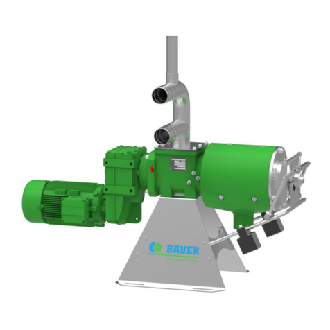
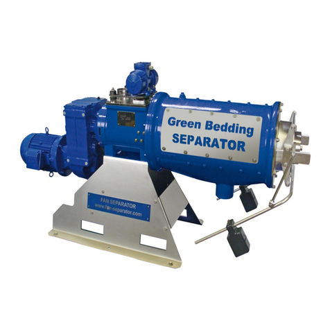
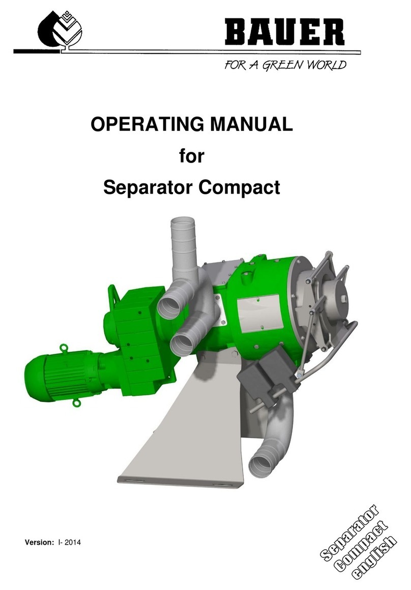
Bauer S655 Installation instructions

ORIGINAL OPERATING MANUAL
FOR
PLUG & PLAY
SEPARATOR SYSTEM
Version: I- 2020

Operating Manual for BAUER PLUG & PLAY Separator System
II
Thank you for buying a BAUER PLUG & PLAY Separator System!
This operating manual is an important document that describes how to operate and maintain the BAUER PLUG
& PLAY Separator System.
All information contained in this manual is based on the latest product details available at the time of printing. If
you need still more information, please ask your dealer or contact the BAUER company directly.
Please note that the content of this manual neither constitutes part of nor alters in any way any previous or
existing agreement, promise or legal relationship. BAUER’s obligations are based solely on the respective pur-
chase contract, which also contains the complete and only valid warranty agreement. Said contractual warranty
is neither extended nor limited by the content of this manual.
The BAUER Plug & Play Separator System is designed for safe and reliable operation provided it is operated
in accordance with this operating manual.
Therefore, please carefully read this operating manual and the manuals for the included components such as
the BAUER separator, BAUER helix pump, discharge pump and the description of the control before starting
up the BAUER Plug & Play Separator System! Strictly observe all instructions pertaining to system handling,
operation and service!
On this condition, the BAUER Plug & Play Separator System will operate to your satisfaction for many years.
The content of this operating manual is the intellectual property of the company BAUER GmbH and/or its sup-
plier companies. The available information may only be used in connection with the creation of specification-
compliant documents in the course of an order from the BAUER Company. Without express written permission
from the BAUER Company, no reproduction or sharing of this operating manual is permitted, even in excerpts.
The BAUER Company reserves the right to make changes at any time without notice and without assuming
any liability!
In the interests of a clearer presentation and due to the large number of possibilities, this operating manual does
not contain all detailed information and, in particular, cannot address every conceivable operating and mainte-
nance situation.
WARNING
Failure to follow this manual may cause personal injury or damage the
equipment!
NOTE
This manual is to be considered an integral part of BAUER Plug & Play Separator
System. Suppliers of both new and used systems are advised to put down in writing
that they delivered the manual together with the system.
Please make this manual available to your staff. Please state the pump type and serial number of your BAUER
Plug & Play Separator System and its components in all inquiries, correspondence, warranty claims or parts
orders.
We wish you great success with your BAUER Plug & Play Separator System!

Operating Manual for BAUER PLUG & PLAY Separator System
1
PRODUCT DETAILS
Type designation: Plug & Play Separator System
Serial number
1
Plug & Play: ____________________________________
Type and serial number Plug & Play Components:
Separator: S655 or S855 ___________________________________
Feed pump: Helix Drive 554 ___________________________________
Discharge pump: B70VBVGMC ___________________________________
Dealer: Name: ____________________________________
Address: ____________________________________
____________________________________
Tel. / fax: ____________________________________
Shipping date: ____________________________________
Producer of the machine: Röhren- und Pumpenwerk BAUER GmbH.
Kowaldstraße 2
A - 8570 Voitsberg
Tel.: +43 3142 200 - 0
Fax: +43 3142 200 –320 /-340
Email: [email protected]om
www.bauer-at.com
Owner or operator: Name: ___________________________________
Address: ___________________________________
___________________________________
Tel. / fax: ___________________________________
Note: Make a note of the type designations and serial numbers of your Plug & Play Separator System, its
components and accessories! Include these numbers along with all contact with your dealer.
1
It is very important to include with all guarantee claims and all correspondence related with this machine the
entire serial number group, including all letters, both for the machine and for its relevant components. This
point cannot be stressed enough.

2
Operating Manual for BAUER Plug & Play Separator System
S

Operating Manual for BAUER Plug & Play Separator System
3
TABLE OF CONTENTS
1GENERAL SAFETY INSTRUCTIONS.......................................................................................................................5
2GENERAL INSTRUCTIONS FOR SAFETY AND ACCIDENT PREVENTION .........................................................7
3FUNCTION DESCRIPTION..................................................................................................................................... 10
4SETUP OF THE PLUG & PLAY SEPARATOR SYSTEM...................................................................................... 11
4.5.1 Information on the Plug & Play Separator System Type Plate.................................................................. 13
4.5.2 Information Signs....................................................................................................................................... 13
5ELECTRICAL CONNECTION................................................................................................................................. 15
6PREPARATION FOR INITIAL STARTUP .............................................................................................................. 16
7INITIAL STARTUP .................................................................................................................................................. 17
7.9.1 Automatic operation................................................................................................................................... 22
7.9.2 Adjusting the pressure set point................................................................................................................ 22
7.9.3 Shutdown of the plant at excess pressure ................................................................................................ 22
7.10.1 Automatic Operation.................................................................................................................................. 23
7.10.2 Manual Operation...................................................................................................................................... 23
7.10.3 Automatic operation with clear effluent pump: .......................................................................................... 24
7.10.4 Automatic operation without clear effluent pump: ..................................................................................... 25
7.10.5 Manual operation with clear effluent pump:............................................................................................... 26
7.10.6 Manual operation without clear effluent pump: ......................................................................................... 27
8PROBLEMS –TROUBLESHOOTING.................................................................................................................... 28
9WINTER OPERATION –TAKING OUT OF OPERATION ..................................................................................... 31
10 MAINTENANCE AND INSPECTION ...................................................................................................................... 31
11 NOTES:.................................................................................................................................................................... 32
12 CONFORMITY DECLARATION.............................................................................................................................. 33

4
Operating Manual for BAUER Plug & Play Separator System
S
LIST OF FIGURES
Figure 1 function description ...........................................................................................................................................10
Figure 2 plug & play diagram...........................................................................................................................................10
Figure 3 Transport aids ...................................................................................................................................................11
Figure 4 main components..............................................................................................................................................12
Figure 5 dimensions Plug & Play Separator System - all dimensions in [mm] .........................................................14
Figure 6 rotation direction of the screw...........................................................................................................................15
Figure 7 motor ciurcuit breakers......................................................................................................................................17
Figure 8 electrical cabinet................................................................................................................................................18
Figure 9 electrical cabinet................................................................................................................................................18
Figure 10 phase monitoring relay...................................................................................................................................18
Figure 11 Bridging switch for break through control........................................................................................................18
Figure 12 fault bridging pressure sensor.........................................................................................................................19
Figure 13 reset button / fault lamp...................................................................................................................................20
Figure 14 OPERATION SWITCH....................................................................................................................................20
Figure 15 remote control .................................................................................................................................................20
Figure 16 AUTO-0-HAND switch.....................................................................................................................................21
Figure 17 switch feed pump ............................................................................................................................................21
Figure 18 switch pressure set point.................................................................................................................................22
Figure 19 switch pump-speed .........................................................................................................................................23
Figure 20 lever and switch position in Automatic operation with clear effluent pump.....................................................24
Figure 21 lever and switch position in Automatic operation without clear effluent pump...............................................25
Figure 22 lever and switch position in manual operation with clear effluent pump.........................................................26
Figure 23 lever and switch position in manual operation without clear effluent pump....................................................27
Figure 24 motor protection switches ...............................................................................................................................28
Figure 25 electrical cabinet main switch..........................................................................................................................28
Figure 26 Plug & Play Separator System.......................................................................................................................31

Operating Manual for BAUER Plug & Play Separator System
5
1GENERAL SAFETY INSTRUCTIONS
This operating manual contains important information that must be observed during setup, operation and
maintenance. For this reason, it must always be read and observed very carefully by the installation techni-
cian as well as the qualified personnel. It must always be available at the usage location of the machine.
If the installation and maintenance of the system are not carried out according to the operating manual, all
claims with respect to defects become void.
The customer is responsible for the proper setup of all equipment. Read the instructions before assembling
or installing the machine. Promised performance characteristics of the machine and the add-on compo-
nents as well as the fulfillment of any warranty claims are dependent on compliance with these instructions.
The CE mark applied by the manufacturer documents the machine’s conformity with the pro-
visions of the Machinery Directive and with other pertinent EC directives.
Warnings and Symbols
The following notes and warnings are used in this operating manual for especially important instructions:
DANGER
Information, requirements or prohibitions to protect against serious injury or prop-
erty damage.
WARNING
Special information on preventing minor injuries or requirements and prohibitions to
prevent damage to the machine.
NOTE
Special instructions to simplify working with the machine or to aid in efficient use of
the machine.
To prevent malfunctions that could directly or indirectly result in serious injuries or property damage,
it is equally important to comply with any other instructions concerning transport, assembly, opera-
tion and maintenance as well as reference data (in the operating manual, the product documentation
or on the equipment itself).
Duty to Furnish Information
When passing the machine on to a new owner, the customer is obliged also to hand over the operating
manual to the new owner. The recipient of the machine must be instructed with reference to the mentioned
regulations.
Should you encounter difficulties in understanding this manual or other instruction, contact the respective
dealer or the BAUER Company for any necessary clarifications.
Product Liability
According to the Product Liability Act, every farmer is an entrepreneur!
In accordance with Section 9 PHG (Product Liability Act), liability for damage to physical property caused by
defective products is expressly excluded. This exclusion of liability also applies to parts not manufactured
by BAUER itself but purchased from external suppliers.

6
Operating Manual for BAUER Plug & Play Separator System
S
Qualified Operators
These are persons who on behalf of their training, experience and instruction as well as their knowledge of
relevant standards, rules, precautions to be taken for accident prevention, and prevailing operating condi-
tions, have been authorized by the person in charge of plant safety to perform the respective tasks re-
quired, and in doing so are able to recognize and avoid potential hazards. The statutory minimum age for
the operating and maintenance personnel must be observed. Among other things, knowledge of first aid
procedures is also required.
Intended Use
The BAUER Plug & Play Separator System is intended exclusively for solid-liquid separation in agricul-
ture, industry and biogas systems (intended use).
Any use of the machine beyond this intended use is considered non-conforming. The manufacturer is
not liable for damage resulting from such non-conforming use, the sole liability for damage from non-
conforming use lies with the user.
Intended use also includes compliance with manufacturer’s operating, maintenance and service instruc-
tions.
The BAUER Plug & Play Separator System may be used and operated only by persons who are familiar
with the system and aware of the hazards involved.
All relevant rules for accident prevention as well as any other generally accepted rules and regulations
relating to safety, occupational medicine and traffic laws must be strictly observed.
Unauthorized modifications to the machine release the manufacturer from liability for damage resulting
from such modifications.
Unauthorized Modification and Manufacture of Replacement Parts
Modifications or alterations to the machine are only permitted after consultation with the manufacturer.
Original replacement parts and authorized accessories from the manufacturer serve the interests of safety.
The use of other parts voids the manufacturer’s liability for any resulting damage.
The replacement parts used must correspond to the technical requirements established by the manufac-
turer of the system. The replacement and wearing parts delivered with the machine or via subsequent or-
ders satisfy this condition.
Disposal
The machine must be disposed of according to the local disposal regulations.
The user must ensure safe and environmentally friendly disposal of operating materials and ancillary mate-
rials as well as replaced parts. Dispose of oil, grease, and filters in accordance with regulations!

Operating Manual for BAUER Plug & Play Separator System
7
2GENERAL INSTRUCTIONS FOR SAFETY AND ACCIDENT PREVEN-
TION
Check the operational safety of the machine before every startup!
All regulations of public authorities that apply to the operation and maintenance of the system must be strictly
observed.
In addition to the operating manual, all generally applicable statutory and otherwise mandatory regulations on
accident prevention and environmental protection must be separately prescribed and observed.
Such obligations may concern, for instance, the handling of hazardous substances, the provision and wearing of
personal protective gear or traffic and road safety regulations.
The operating manual should be extended with the instructions for taking into account special operating condi-
tions, such as with regard to the work organization, work processes and the active personnel. The supervisory
and reporting obligations of the operator must also be clearly regulated.
To ensure your safety and the safety of your employees, every person who is responsible for operating the system
must also be familiar with these obligations. It is too late for this when the system is already running!
The personnel assigned to operating the plant must have read the operating manual and in particular the section
“General Instructions for Safety and Accident Prevention” before starting work.
Every person must be aware of the safety measures that must be complied with during work on electro-mechanical
components and machines.
Only trained personnel may enter the hazard zone of the machine.
Only trained personnel may be assigned to work with the machine. The respective competencies of the personnel
for the operation, setup, maintenance and repair of the machine must be clearly defined. It must also be ensured
that only appropriately authorized personnel work on the system.
Personnel, who are being trained, taught, instructed or are participating in a general training program may only
work on the system under the constant supervision of a person experienced in operation of the system.
The safety- and risk-conscious work by the personnel in compliance with the operating manual must be checked
at least at certain intervals.
The personnel assigned to operate the machine may not have:
Exposed long hair
Loose clothing
Jewelry, including rings and drop earrings
Such items could get stuck and/or drawn into the machine, resulting in possible injuries.
The operating personnel of the system must be familiarized with the fire alarm and fire-fighting options.
The wearing of personal protective gear such as hearing protection, safety glasses, safety shoes, etc. during
operation of the system must be required by means of rules or regulations.
All safety information and warnings present on the system must be pointed out, and these must be kept on the
system in a clearly visible and legible condition.
In event of safety-relevant changes to the system or its operating behavior, the system must be immediately shut
down and the fault must be reported to the competent person or office.
Replace pipelines and hoses in the specified or otherwise reasonable intervals, even if no operationally relevant
defect is discernible.
Intervals that are required or specified in the operating manual for regular daily, weekly and monthly inspections
and tests must be complied with. Appropriate tools and equipment must be kept available for the performance of
such work.
Any potentially unsafe work on the machine must be avoided. The system may only be used in accordance with
its intended use. All necessary measures must be taken to ensure that the system is only operated in a safe and
fully functional condition.
The system may only be started up if all protective and safety-related features are fully functional. This includes
the fact that all removable protective features, EMERGENCY OFF buttons and covers must be present and
functional.
The system must be inspected for externally identifiable defects before it is started up each time. Any changes
that occur, including changes to the operating behavior and functional disruptions, must be immediately re-
ported to the competent party. The system must be immediately shut down and secured.
WARNING

8
Operating Manual for BAUER Plug & Play Separator System
S
If the following damage or malfunctions are discovered on the machine, operation of the machine must be
stopped immediately.
Defects, damage or cracks on the load-bearing parts, bearings, hydraulic components or safety equip-
ment
Damage to electrical cables
Unusual noises
Unusually fast or slow movements on the machine
Errors in the operation or control of the machine
Leaks on hoses, valves or the machine itself
Procedures for switching the machine on and off as well as inspection of the control indicators must be carried
out as described in the operating manual.
Before switching on or starting up the machine, it must be ensured that no one will be endangered by the start-
ing up of the machine.
The correct functioning of the control must be checked before the start of work. Before startup, all tools and as-
sembly aids must be stored safely to prevent accidents.
The maintenance, configuration and inspection intervals specified in the operating manual must be complied
with. The specified intervals are maximum deadlines and may not be exceeded. Such work as well as the re-
placement of components may only be performed by qualified personnel.
During transport of the Plug & Play Separator System, measures must be taken to ensure sufficient securing of
the transport area.
The required switch-on and switch-off procedures according to the operating manual and the instructions for
maintenance work must be observed during all work involving the operation, production adaptation, conversion
or configuration of the system and its safety-related features as well as all work involving inspection, mainte-
nance and repair.
The operating personnel must be informed of special work, repair work or conversion work in a timely fashion
prior to starting the work. A supervisor must always be appointed during the performance of such work.
The work area must be blocked off and secured by a wide margin during such work, if necessary. Unauthorized
persons must be prevented from entering.
As a rule, maintenance and cleaning work as well as repairs of malfunctions may take place only with the drive
switched off and the motor at rest (switch off and lock the main switch or disconnect the supply of electricity).
Watch out for the unexpected starting of the system.
It must be noted that a pressed EMERGENCY OFF button does not provide any protection against unauthorized
starting of the machine.
During disassembly and assembly, large individual parts and entire assemblies must be carefully fastened and
secured to lifting equipment. Only suitable lifting equipment and load handling devices with sufficient carrying
capacity and no technical operating defects may be used. Standing or working under suspended loads is not
permitted. Grips, steps, railings, landings, platforms and ladders must be cleaned of oil, dirt, snow and ice be-
fore all activity on the system.
Securing of personnel with suitable supporting elements is required during all maintenance work on an elevated
system.
During assembly work above head height, climbing aids and work platforms intended for such work or specially
adapted for purposes of safety must be used. Never use system components as climbing aids. The system and,
in particular, connections and bolt connections must be cleaned of oil, grease or care agents prior to the start of
maintenance or repair work. No aggressive cleaning agents may be used. Only fiber-free cleaning cloths may
be used.
Before cleaning the system with water, steam, high-pressure cleaners or other cleaning aids, cover / tape over
all openings into which no water, steam or cleaning agents may enter for safety and/or functional reasons. Elec-
tric motors and electronic switch cabinets are at particular risk. After cleaning, the applied covers / tape must be
completely removed again.
Wear appropriate protective gear to protect against flying particles while cleaning with compressed air or steam
jets.

Operating Manual for BAUER Plug & Play Separator System
9
After cleaning, all gear oil and media lines as well as all electrical connections must be inspected for leaks, loos-
ened connections, abrasions and damage. Identified defects must be corrected immediately.
The bolt connections loosened during maintenance and repair work must be tightened again. Observe the re-
quired tightening torques.
If it is necessary to remove safety features during maintenance, setup or repair, the safety equipment must be
re-installed and inspected immediately after completion of the work.
Do not start the machine unless all guards and safety devices are mounted completely and in proper working
position!
Protective caps and covers may not be removed.
The stickers affixed to the device with safety and warning signs provide important instructions for safe operation;
following these instructions is intended to keep you safe! These may not be removed.
Check the proper seat of nuts and bolts regularly, and tighten them, if needed!
When replacing operating elements with blades, use a suitable tool and wear gloves.
The system is electrically operated. Take special care when performing work in the area of electrically operated
system components.
Maintain the minimum distances with respect to electrical lines. Otherwise, the electricity must be switched off or
the work area restricted.
Keep a sufficient distance to electrical cables; if this is not possible, the electricity supply must be interrupted or
the work area restricted.
Distance to 1,000 volt lines: at least 1 meter.
Work on electrical and electronic components of the system may only be performed by a trained electrician or
otherwise appropriately trained personnel under the guidance and supervision of a trained electrician in accord-
ance with the applicable electrical and electronic regulations.
With regard to an ATEX 95 zone 22 certification, see the special remarks.
Never touch rotating or moving parts of the machines with hands or feet.
Never reach with hands, tools or other parts into the inflow or hopper in the area of the screw while the machine
is running.
In handling slurry, always remember that the gases produced by the slurry are highly toxic and explosive in com-
bination with oxygen. Open flame, light checks, spark creation and smoking are therefore prohibited!
When using the retention or alternating retention method, special care must be taken in the area of the opened
sliding gates to the pre-pool before the main tank or to cross channels due to the formation of gases. In addition,
special care is required at stirring and withdrawal points while the stirring machines or pumps are active.
Keep the machine clean to decrease the risk of fire.
Always ensure sufficient ventilation when working with slurry.
When working with biologically active materials in connection with the BAUER Plug & Play Separator System or
connected components, the decomposition of these materials can lead to the production of life-threatening gases,
especially in enclosed spaces. Always ensure sufficient supply and exhaust ventilation and/or appropriate protec-
tive clothing before entering such areas.
DANGER
In addition to the mechanical dangers of moving parts or parts under pressure, the operation
of slurry handling machines also poses risks in connection with gases produced by liquid ma-
nure. These gases (carbon dioxide CO2, ammonia NH3, hydrogen sulfide H2S, methane CH4)
can result in poisoning as well as explosions.
Especially when operating mixers, stirring machines, recirculation systems, pipe nozzles and
slurry aeration systems, care must be taken that no gases can flow into the barn from exterior
tanks or containers (install siphons or sliders).
Sufficient forced ventilation of the barn area must be ensured while handling slurry in the barn
area.

10
Operating Manual for BAUER Plug & Play Separator System
S
Equation 1
3FUNCTION DESCRIPTION
The BAUER Plug & Play Separator System is a compact mobile separation unit with all components installed
within a minimal space in order that these can be transported quickly and easily to another location. It serves
for separating pump able slurry (solid-liquid mixtures with relatively low solid matter content and no foreign
bodies such as metal parts, stones, wood or rags) into solid and liquid (thin slurry, effluent) fractions. As a
compact device, it contains the following components: separator, eccentric screw pump as feed pump, rotary
discharge pump and electronic control mounted to a stable frame with forklift-compatible features. The indi-
vidual components are optimally integrated into the design for guaranteed stability and a long lifespan.
The BAUER Plug & Play Separator System is designed for sustained operation outdoors. It operates unim-
paired in a temperature range of 0 to +40°C; in event of freezing temperatures, it must be ensured that the
separator, feed pump and discharge pump as well as all pipelines are cleaned completely each time before
being taken out of operation.
The eccentric screw pump is controlled by a pressure sensor and feeds the slurry to the separator. In the
inflow area of the separator, the mixture is drained of water via gravity inside the sieve. The interior screw
transports the pre-drained material horizontally toward the solid outlet. Along the last section of the transport
path, the screw presses out additional liquid, which escapes the separator through the sieve without pressure
as thin slurry.
The required contact pressure is applied to the escaping solid by a system consisting of a cap loaded by a
weighted lever. The liquid phase can be transported into a lagoon or elevated tank, for example, using the
available clear flow pump.
Raw liquid manure
Contact pressure
Transport and pressing screw (30 rpm)
Sieve element
Solid phase
Liquid phase
Disposal solid
gate valve
Figure 1 function description
Figure 2 plug & play diagram
Gate valve

Operating Manual for BAUER Plug & Play Separator System
11
4SETUP OF THE PLUG & PLAY SEPARATOR SYSTEM
Condition of the BAUER Plug & Play Separator System upon Delivery
The BAUER Plug & Play Separator System was developed by BAUER GmbH. It is delivered as a complete
unit (separator, feed and discharge pumps, incl. pipelines and control).
You must connect the switch cabinet to the electrical supply. Connecting the system to the feed or clear
flow line using the supplied hoses, if included, completes the installation of the Plug & Play Separator Sys-
tem.
DANGER
Work on electrical and electronic components of the system may only be performed
by a trained electrician or otherwise appropriately trained personnel under the guid-
ance and supervision of a trained electrician in accordance with the applicable elec-
trical and electronic regulations.
Required Tools
Special tools are not required for setting up the Plug & Play Separator System.
Standard assembly and electrical tools are required for assembly, setup and disassembly.
Transport
Improper transport could cause the device to fall or tip. Severe injuries could result!
The customer must check based on the dimensions and weight of the Plug & Play Separator System whether
the available lifting equipment (forklift or crane, with corresponding belts or chains) is sufficient for setting up
the Plug & Play Separator System.
The Plug & Play Separator System may only be lifted as follows:
By forklift: At the provided lifting points (2x) for forklift forks
The following points must also be taken into account:
The feed pump and discharge pump as well as all lines should be pumped empty.
Move the slide plate to the transport position (vertical)
The transporter must ensure that the BAUER Plug & Play System is tied down properly.
Slide plate
WARNING
Lifting points for forklift
WARNING
Figure 3 Transport aids

12
Operating Manual for BAUER Plug & Play Separator System
S
12
Features, Identification and Information
An overview of the components of the BAUER Plug & Play System is provided in Fig.4 Every BAUER Plug
& Play System is adapted precisely to the customer requirements before assembly and configured
accordingly. This means that every BAUER customer receives a P&P system that is perfectly adapted to
his needs.
The precise article numbers of the wearing parts and replacement sets as well as the exploded view of the
main components can be found in the replacement parts list.
No. Name
1 Separator
2 Helix Drive (eccentric screw pump)
3 Rotary discharge pump (clear flow pump)
4 Switch cabinet
5 Frame with doors
6 Slide plate
7 Helix suction line (eccentric screw pump)
8 Separator supply line (Helix pressurized line)
9 Separator overflow line
10 Clear flow line between separator and clear flow pump
11 Discharge line from clear flow pump
12 Clear flow line
13 Forklift lifting points
14 emergency stop
Figure 4 main components
9
1
8
7
4
2
10
11
3
13
5
6
14

Operating Manual for BAUER Plug & Play Separator System
13
Type plates
When you contact your dealer or communicate directly with BAUER GmbH about wearing part or replace-
ment part inquiries, you will be asked for your serial number and machine number in order to ensure faster
assistance.
The type, year of manufacture and serial number of the Plug & Play Separator System are given on the
type plate, which is located on the frame. Additional type plates are affixed to the individual components,
such as separator, geared motor of the separator on the feed and discharge pumps.
4.5.1 Information on the Plug & Play Separator System Type Plate
The BAUER Plug & Play Separator System type plate contains the following information:
Separator type: Plug&PlayS655/S655HD or Plug &PlayS855/S855HD /S855GB
Serial number: e.g. PP1807001 (PP means Plug&Play, 18 is the year,
07 the month, 001 is a three-digit incremental number)
Required connected power: 17.2 kW P&PS655/S655HD/S855;
19.2 kW P&PS855HD/S855GB
Year of manufacture: e.g. 2018
Weight: Depends on separator type
4.5.2 Information Signs
Information signs can be found on the individual main components, such as the Bauer separator, Bauer ec-
centric screw pump and rotary discharge pump and are explained in the individual operating manuals.
Any damaged signs must be replaced. These can be ordered from your dealer.
Technical Data of the Plug & Play Separator System
Separator
BAUER Separator S655 / S655HD
BAUER Separator S855 / S855HD / S855GB
Feed pump
BAUER Helix Drive
Clear flow pump
Rotary pump
Plug & Play frame
Steel, galvanized
Helix suction line
Existing connection BAUER cup HK133 –steel, galvanized
Clear flow line
Existing connection BAUER ball HK108 –steel, galvanized
Separator overflow line
Existing connection BAUER ball HK108 –steel, galvanized
Control
Required connection power: 17.2 kW for PP655/PP655HD/PP855
19.2 kW for PP855HD/PP855GB

14
Operating Manual for BAUER Plug & Play Separator System
S
Setup and Assembly
The basic dimensions of the BAUER Plug & Play Separator System for determining the dimensions of the
setup location are shown in Fig. 5
PP655
PP855
A
in transportposition
2940
3010
B
2005
2005
C
support inside
190
190
D
1180
1180
E
80
340
F
400
470
G
990
990
H
1165
1165
I
980
980
J
1705
1705
K
2515
2515
L
3640
3640
Figure 5 dimensions Plug & Play Separator System - all dimensions in [mm]

Operating Manual for BAUER Plug & Play Separator System
15
5ELECTRICAL CONNECTION
DANGER
Work on electrical and electronic components of the system may only be performed
by a trained electrician or otherwise appropriately trained personnel under the guid-
ance and supervision of a trained electrician in accordance with the applicable elec-
trical and electronic regulations.
WARNING
Fuses do not protect the motor from overloads; they only protect the electrical supply
lines or switching systems from damage in event of a short-circuit.
WARNING
Set the motor protection circuit breaker to the value specified on the motor type
plate ( IRated/IN/I∆)
In forward motion, the screw shaft turns counterclockwise.
(As viewed from the discharge regulator toward the geared motor)
This can be checked with the phase monitoring relay
“1F2” in the switch cabinet:
Direction of rotation correct Indicator light is on (steady)
Direction of rotation incorrect: Indicator light is off
If the direction of rotation is incorrect, two of the current-carrying
conductors “L1” and “L2” in the switch cabinet are swapped.
Viewing direction
Figure 6 rotation direction of the screw

16
Operating Manual for BAUER Plug & Play Separator System
S
6PREPARATION FOR INITIAL STARTUP
WARNING
It must be ensured that no large foreign bodies such as metal parts, stones, wood
pieces or rags enter into the separator; such objects would otherwise overload the
sieve and the screw in particular. It should also be noted that abrasive media (e.g. high
sand content) will reduce the service life of the screw shaft, sieve and stator of the
eccentric screw pump.
Before beginning the startup process, check the following measures:
1. Place the Plug & Play Separator System on a flat, hard surface.
2. Check: Whether the machine is horizontal (level)
3. Check: Supply line between slurry pit, eccentric screw pump and separator connected and sealed
4. Check: Overflow line (if necessary) connected and sealed
5. Check: Line for discharge of the separated slurry connected and sealed
6. Check: Slider and ball valve position of the clear flow line:
Operation with clear flow pump: gate valve closed –ball valve open
Operation without clear flow pump: gate valve open –ball valve closed
7. Fill the feed pump / eccentric screw pump (suction line) completely with liquid to prevent damage to
the rotor and stator of the pump.
8. Make sure that the press head and the functioning of the separator can be seen clearly from the switch
cabinet [it must be possible to watch the solid cake and its discharge speed].
9. Supply with sealing medium: When using grease as the sealing medium, 3 to 5 cm3of grease must
be introduced via the lubricating nipple to fill the labyrinth seal before initial startup. (See also the
Separator operating manual, section 13.1.1)
10. Check the oil level in the separator gearbox and top up, if necessary; properly dispose of old oil.
11. Remove the weights (minimum closing force)
12. Check: Whether all power cables are in perfect condition before connecting the machine to the
power network.
13. Connect the Plug & Play Separator System to the power network
14. Set the motor protection circuit breaker to the required rated current.
15. After switching on, check the correct direction of rotation (see section 5); note the arrow on the press
head, switch motor off again.

Operating Manual for BAUER Plug & Play Separator System
17
7INITIAL STARTUP
NOTE
Before starting up the system, please read the operating manual of the sepa-
rator, eccentric screw pump and control (see attachment)
NOTE
The reaction time before each setting change takes several minutes, meaning
that the effect of any change can only be determined after this time.
For this reason, always allow enough time after making a change and only make
changes in small steps!
NOTE
Before the initial startup and after prolonged downtime, the separator should
be flooded before switching it on by starting the pump briefly in order to pre-
vent possible damage from dry running.
NOTE
In order to achieve good separating results, it is necessary to mix the
pumped medium well before separating.
Motor circuit breakers:
All motor protection switches (5F1, 5F2, 5F3, 6F1, 6F2, 7F1) check on the proper nominal current of the
respective electric motors or set and then activate
Figure 7 motor ciurcuit breakers
2F1
7F1
6F2
6F1
5F3
5F2
5F1

18
Operating Manual for BAUER Plug & Play Separator System
S
Figure 9 electrical cabinet
Main switch of the electrical switch cabinet
Set main switch on the
electrical cabinet
to position “ON/1” = vertical
Check direction of rotation:
Check the direction of rotation of the separator screw using the phase monitoring relay “1F2” in the
switch cabinet. The screw must run counterclockwise as seen from the press head.
Direction of rotation correct: Indicator light is on (steady) see figure 10
Direction of rotation incorrect: Indicator light not lit Swap lines L1 and L2
Press reset button 2x (please refer figure 13)
Bridging switch for break-through-control
For starting the unit, the break-through-control can be bridged manually (Switch Position „ON“). After
the plug has been built and the flaps are in working position, the bridging can be ended (Switch Po-
sition „OFF), after that, the break-through-control is active.
Figure 11 Bridging switch for break through control
Indicator light
light
ELECTRICAL CABINET
MAIN SWITCH
Figure 10 phase monitoring relay
1F2
Bridging switch
for Break-through control
OFF - ON
Figure 8 electrical cabinet
main switch
DIRECTION OF ROTATION
OK
OPÉRATION
OK
RESET
OPERATION
AUTO - 0 - HAND
SETPOINT PRESSURE
0,1-0,3bar
PUMPSPEED IN MANUAL
OPERATION
5-80Hz
HOUR METER
HELIXPUMP
BREAKTROUGHT SWITCH BRIDGING
OFF - ON
HOUR METER
SEPARATOR
PRESSURE SENSOR BRIDGING
OFF - ON
This manual suits for next models
1
Table of contents
Other Bauer Water Filtration System manuals
Popular Water Filtration System manuals by other brands

Synergy Science
Synergy Science Echo H2 MACHINE Owner's operation manual

Judo
Judo MAFI Series Installation and operating instructions

Vertex Water Products
Vertex Water Products PureWaterMachine PT-4.0 Owners & installation manual

PUR2o
PUR2o Alkaline Plus Installation instructions manual

Ispring
Ispring RO1000 Series Installation instructions & user manual

AEG
AEG AquaSense manual