Vertex Water Products PureWaterMachine PT-4.0 Quick start guide

VERTEX
Water Products
PureWaterMachine
REVERSE OSMOSIS UNDERSINK
WATER FILTRATION SYSTEM
OWNERS INSTALLATION
MANUAL
™
VERTEX WATER PRODUCTS

WQA GOLD SEAL APPROVAL: The Pure Water Machine filter has been tested and certified
by the Water Quality Association according to NSF/ANSI 58 for the reduction
of contaminants. See the Performance Data Sheet, page 14 & 15, for specific substances
and reduction performance.
The VERTEX PURE WATER MACHINE is made with quality components to provide cleaner,
safer drinking water.No chemicals areadded or used in this system. Topreserve the GOLD
SEAL approval and filter capability, it is required that the filter elements be replaced at the
intervals and with replacement elements as specified in section 4.0 of this manual.
This manual is applicable to Product Models:
PT-4.0 PT-4.0/50
PT-4.0/P PT-4.0/P/50
PT-4.0/5 PT-4.0/5/50
PT-4.0/5/P PT-4.0/5/P/50
Nitrate/Nitrite Test Instructions
If you purchased your system specifically for nitrate reduction, Vertex recommends
testing with the kit supplied herein to establish that nitrate and nitrite are being reduced to
acceptable levels.
Werecommended tests be made on the filtered water each 6 months to assume it con-
forms. Open the PurTest package, take out one strip. Insert a strip in a sample of filtered
water for a few seconds, then withdraw and wait for 60 seconds. Color change on the end
pad is for nitrate, and the upper pad is for nitrite.
Replacement test kits may be purchased from your dealer.
Each 6 months, the water should be sent to a certified water laboratory, or to the coun-
ty for tests on the filtered water for any additional items of concern.

Table of Contents
i.Notice
ii.Parts List
1.0 Introduction . . . . . . . . . . . . . . . . . . . . . . . . . . . . pg. 1
2.0 Installation . . . . . . . . . . . . . . . . . . . . . . . . . . . . pg. 2
2.1 Location of RO Unit . . . . . . . . . . . . . . . . . . . . . . . . . . . . . . . pg. 2
2.2 Mounting the RO filter Unit Under a Sink . . . . . . . . . . . . . . . . pg. 2
2.3 Install RO Membrane Element In Housing . . . . . . . . . . . . . . . . pg. 4
2.4 Connecting the FeedWater Supply . . . . . . . . . . . . . . . . . . . . . . pg. 4
2.5 Installation of Drain Connection . . . . . . . . . . . . . . . . . . . . . . . pg. 5
2.6 Installation of Clean Water Faucet . . . . . . . . . . . . . . . . . . . . . . pg. 6
2.7 Porcelain/Enamel Over Steel or Cast Iron Sinks . . . . . . . . . . . . . pg. 6
2.8 Install Faucet . . . . . . . . . . . . . . . . . . . . . . . . . . . . . . . . . . . . pg. 7
2.9 Tubing Connections . . . . . . . . . . . . . . . . . . . . . . . . . . . . . . . . pg. 7
2.10Air Gap Faucet Installation . . . . . . . . . . . . . . . . . . . . . . . . . . pg. 9
3.0 System Start Up . . . . . . . . . . . . . . . . . . . . . . . . . pg. 9
3.1Air Purge . . . . . . . . . . . . . . . . . . . . . . . . . . . . . . . . . . . . . . . pg. 9
3.2 Start-Up . . . . . . . . . . . . . . . . . . . . . . . . . . . . . . . . . . . . . . . . pg. 9
4.0 Recommended Filter Changes . . . . . . . . . . . . . . . . . pg. 10
4.1 Filter Replacement, Pure Water Machine . . . . . . . . . . . . . . . . . . pg. 10
4.2 Standard Filter Elements . . . . . . . . . . . . . . . . . . . . . . . . . . . . . pg. 11
5.0 Filter Replacement Procedure . . . . . . . . . . . . . . . . . pg. 11
6.0 Installation Troubleshooting . . . . . . . . . . . . . . . . . pg. 13
7.0 Two-Year LimitedWarranty . . . . . . . . . . . . . . . . . . pg. 13
8.0 Performance Data Sheet . . . . . . . . . . . . . . . . . . . . pg. 14
9.0 Other Models . . . . . . . . . . . . . . . . . . . . . . . . . . . pg. 15
9.1 Pure Water Machine with booster pump . . . . . . . . . . . . . . . . . . pg. 15
Appendix A: Theory of Operation . . . . . . . . . . . . . . . . . pg. 17
A.1 Pre Filters . . . . . . . . . . . . . . . . . . . . . . . . . . . . . . . . . . . . . . pg. 17
A.2 The Reverse Osmosis Membrane . . . . . . . . . . . . . . . . . . . . . . . pg. 17
A.3Auto Control . . . . . . . . . . . . . . . . . . . . . . . . . . . . . . . . . . . . pg. 18

iNOTICE
This instruction manual was written to guide a professional plumber to make an easy
installation of the VERTEX Pure Water Machine. The installation shall conform to state
and local laws and regulations.
This manual covers systems with 36 allon per day membranes (PT-4.0, PT-4.0/P, PT-
4.0/5, PT-4.0/5/P) and systems with 50 gallons per day membranes (PT-4.0/50, PT-
4.0/P/50), PT-4.0/5/50, PT-4.0/5/P/50).
This filter system can be installed by the homeowner who has sufficient tools and
skills. Be cautioned that an extra faucet for purified water will be installed . This requires a
7/8-inch diameter hole in the sink top. If there is not an extra hole existing, a new one
must be drilled. For a porcelain sink, this requires a special drill (7/8" Relton cutter) which
costs about $160 and requires skill to use.
ii PARTS LIST
PARTS CONTAINED IN THE PURE WATER MACHINE CARTON
1-Box containing storage tank
1-Box with filter assemblies
1-Set of 1/4" plastic tubes, orange, white, black
1-clean water faucet and fittings
1-set of hardware consisting of:
Inlet water 1/4" ball valve and 1/2" feed line adapter
1/4" plastic ball valve for tank shutoff
Drain saddle clamp
5-pcs. Tube inserts
OPTIONAL
1-Pump Transformer - for models with booster pump

1.0 INTRODUCTION
The VERTEX Pure Water Machine is a 4-stage water cleansing system. The princi-
pal cleansing of the water of dissolved solids is by the Reverse Osmosis membrane filter
(stage 3).
Stage One is a sediment filter which removes particles of rust, sand and other trash in
the water line down to 5-microns in size.
Stage Two is an activated carbon block filter which removes odors, chlorine and for-
eign tastes.
Stage Three is an advanced reverse osmosis membrane for removal of dissolved solids.
This is the heart of the system. The reverse osmosis technology on average removes
95% of the dissolved solids. Dissolved solids are not removed by municipal water treat-
ment systems. This is why the Vertex Pure Water Machine is an important safety factor for
the water you drink and use in your cooking. Chemical contaminants such as chromium-
6, lead, nitrates, and selenium which seep into municipal water systems are removed.
The water pressure against the reverse osmosis membrane forces the water molecules
through the membrane, but the larger contaminant molecules are kept behind and are
flushed to the sewer.The clean water goes to the storage tank and is held there ready to use.
When the faucet is opened, clean water from the storage tank flows through the acti-
vated carbon polishing filter to the faucet for your use. The tank is prepressurized with a
bladder which pushes the water out through the final carbon filter.
A special faucet is installed on your sink which dispenses safe, good tasting drinking
water which is especially good for coffee, tea and drinks. By extending a line to your refrig-
erator, it can be used to make ice cubes.
LIFE. The filter life is specified by the number of gallons of water flowing through
the system. Normal household will use two to three gallons of purified water daily.The fil-
ters are good for 1500 to 3000 gallons total usage depending on water quality.Therefore
the filter elements, Stages 1,2, & 4 should be changed at least once a year. The Reverse
Osmosis membrane has a longer effective life-span (5-year maximum) and it should be
changed once every three years. See section 4.0
5-stage systems have an additional carbon pre-filter. All other stages are the same as
described above.
-1-

2.0 INSTALLATION
Before starting the installation, you should measure the water pressure that is avail-
able under the sink to power the Pure Water machine RO. If the pressure is less than 40-
psig, it is too low; and if it is 90-psig, it may be too high. The solution if the pressure
is too low is to use a model with a booster pump. The solution for high water pressure,
is to put a pressure regulator in the inlet water line to the house. A pressure of 60-75 psig
is normal.
2.1 Location of RO unit
The RO unit may be located under the kitchen sink or in the basement. A cold
water supply line must be close by. When locating the system under a sink make sure
there is adequate room for the filter module assembly as well as the storage tank. For
best performance the tank should be located as close to the clean water faucet (sup-
plied) as possible (within 20 feet).
2.2 Mounting the RO filter unit under a sink (Fig. 1.)
Mount the unit to the wall of the sink cabinet. Pre-fit the unit by positioning the bot-
tom of the pre-filter cartridges 2 inches off the floor of the cabinet. This clearance is nec-
essary to make room to remove the housings when replacing the filter cartridges. Mark
the location of the 2 mounting holes in the mounting bracket. Install 2 mounting screws
leaving 1/8 inch clearance under the screw head. Check the fit by mounting the RO filter
unit but don’t install yet.
A 1/4” ball valve is supplied so the homeowner can easily shut off feed water when
leaving the home unattended. The best overall protection from potential water leaks in the
kitchen, hot water heater, or utility room is to install an automatic leak detector shutoff
valve to the house (Vertex P/N LC-8021).
-2-

-3-
Fig. 1.
RO SYSTEM TOP VIEW
Regular
Faucet Clean Water
Faucet
Drinking Water Line
from Post-Filter to Faucet
(1/4” white tubing)
Tap Water Feed
Line to Pre-Filter
(1/4” orange tubing)
Drinking Water
Storage Tank
Drinking Water Line
to Storage Tank
(1/4” yellow tubing)
Stage 2
Pre-Carbon
Stage 1
Pre-Filter
Stage 4
Post-Filter
Stage 3
Romembrane
Drain Clamp
Assembly Slip Joint
Adapter
Existing
Water
Line
Install
Ball Valve
Drain Line
(1/4” black tubing)
Figure 1
Check Valve
Regular
Faucet Clean Water
Faucet
Drinking Water Line
from Post-Filter to Faucet
(1/4” white tubing)
Tap Water Feed
Line to Pre-Filter
(1/4” orange tubing)
Drinking Water
Storage Tank
Drinking Water Line
to Storage Tank
(1/4” yellow tubing)
Stage 2
Pre-Carbon
Stage 1
Pre-Filter
Stage 4
Post-Filter
Stage 3
Romembrane
Drain Clamp
Assembly Slip Joint
Adapter
Existing
Water
Line
Install
Ball Valve
Drain Line
(1/4” black tubing)
(4-STAGE SYSTEM SHOWN)

-4-
2.3 Install RO membrane element in housing (See Figure 2)
The RO membrane element is packed separately because the membrane has been
tested by the manufacturer and sealed in plastic with preservative. Remove the membrane
element from its sealed plastic bag. To install the membrane in the housing first loosen the
inlet fitting nut (the end of the housing with the single fitting) and remove the tube.
Unscrew the membrane housing cap. Notice that one end of the RO membrane has two
“O” rings on it. This end slides in first. Check that the “O” rings are tight and in their
grooves. Lubricate lightly with cooking oil or vaseline. Install the membrane so the black
sealing ring on the membrane is at the open end of the housing. Press the membrane in and
feel the two “O” rings seat in the housing. Make sure they seat properly on the barrel of the
housing, then reinstall the housing end cap and tighten securely.Reinstall the tubing and
fitting and secure fitting nut.
2.4 Connecting the feed water supply (Fig. 3)
The feed water assembly consists of 1/2” brass slip joint adapter,ablack wash-
er,and a 1/4” x 1/4” ball valve. Locate these parts in the installation kit.
Locate the cold water shut offvalve under the sink and turn it off. Open the cold
water faucet to release the pressure. On single handled faucets, the hot water may
have to be turned off to prevent any hot water cross-over. If water continues to come
out of the faucet with the under-sink valvesturned off, the house main valve will have
to be turned off.
With the water turned off, disconnect the cold water riser tube (flex line) from
the valve. Install the slip joint connector with the black washer. Loosen the nut and
separate the cold riser tube from the faucet shank. Gently bend the riser tube so that
the slip joint adapter fits onto the faucet shank. Reinstall the cold riser tube on the
slip joint connector using the existing cone washer. For Solid copper tube the proce-
dure is the same except you must cut a piece of the riser tube about 3/4” to 1” so the
slip joint adapter can fit between the valve and the riser tube. Wrap several turns of
M
ME
EM
MB
BR
RA
AN
NE
EI
IN
NS
ST
TA
AL
LL
LA
AT
TI
IO
ON
N
RO Membrane Element
"O" Ring Seals
Membrane Housing
Figure 2
End Seal

-5-
teflon tape on the ball valve and install on the slip joint connector.
In some cases the Pure Water Machine is supplied with a saddle Valve which can
clamp over a copper pipe and make the hole and seal at once. (See figure 4).
Figure 3 Figure 4
2.5 Installation of drain connection (Fig. 5)
Place the drain outlet saddle on the drain pipe. Allow proper space for the drilling
operation. Tighten the saddle bolts evenly on both sides. Using the opening in the drain
outlet saddle as a guide, drill a 1/4” hole in the drain pipe. Clean any debris out of the drain
saddle connection.
Existing Cold Water
Line to Sink
1/4” Tubing
(orange)
Ball Valve
Rubber
Grommet
1/2” Slip Joint
Adapter
Black Washer
Existing Cold Water
Supply Valve
Valve with
Piercing Point
1/4” Feed
Clamp
Copper
Water
Line
Vertical
Mount
Foam
Sealing
Washer
Compression
Fitting
1/4” tube
(black)
Horizontal
Mount
Do Not
Mount Here
Disposal
Sink Sink
Maximum Displacement
from Top Center – 30˚
RO Drain Line
Figure 5

-6-
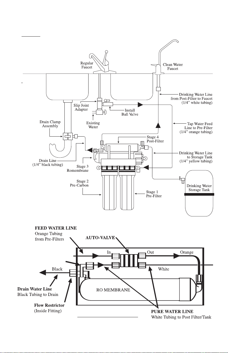
2.6 Installation of clean water faucet (Fig. 6)
The faucet should be positioned
with aesthetics, function, and con-
venience in mind. An ample flat
area is required for the faucet base
so that it can be drawn down tight.
The space under the sink below
where the faucet will be mounted
must be clear of any obstructions.
Some conditions may eliminate
the need to drill a hole in the sink
such as a faucet previously
installed in the sink, a hole cov-
ered by a chrome hole cover, or an
unused spray handle. If any of
these situations are present, you
may mount the faucet in one of
these holes.
The sink drilling process is not
complicated, but requires a certain
amount of caution and fore-
thought. Porcelain sinks can be
chipped if care is not exercised
when drilling the hole for the
faucet.
[NOTE: This procedure is for the non air gap faucet provided.]
2.7 Porcelain/Enamel over Steel or Cast Iron Sinks
Using a small diameter carbide tipped drill, drill a pilot hole completely through the
porcelain and the material underneath. Remove any metal chips that fall into the sink to
prevent rust stains. Place the spring-loaded porcelain cutter bit in to the drill chuck. Make
sure the pilot guide is insertedtightly. Insert the pilot guide onto the pilot hole. Push down
gently on the drill motor to apply light pressure to the porcelain surface. Start the drill
motor, turning as slowly as possible. After the initial cut has started, motor speed may be
gradually increased. The cut may require three to four minutes to complete. Going faster
could result in excessive chipping. Be sure a complete ring has been cut through the porce-
lain to the metal underneath.
Place the finish hole saw into the drill chuck. Make sure the pilot guide is inserted
tightly. Insert the pilot guide into the pilot hole. Begin cut using a slow speed and light
pressure until the porcelain has been penetrated to the material underneath. Remove the
saw from the hole and clean all debris from the porcelain surface. Reinsert saw into the
hole and cut through the remaining material.
Step 1.
Pilot Drill
Step 3.
Finish Hole
Saw
Step 2.
Spring Loaded
Porcelain Saw
(Relton Cutter)

-7-
2.8 Install Faucet (Fig. 7)
Disassemble the hardware from the threaded stud except for the top base plate and
sealing gasket. Install the faucet in the sink hole. From below the sink assemble the
mounting hardware. Use a deep socket to tighten the nut.
2.9 Tubing Connections (Fig. 8)
a.
The standard tubing connections on the Pure Water Machine are of “JACO”
design and manufacture. Use the tubing sections provided and the tubing inserts.
Follow the instructions in Figure 7 to make the connections. Use a 5/8” open-
end wrench to tighten the JACO nuts on the tube. Hand tightening is not suffi-
cient and may lead to leaks. MAKE SURE THAT THERE ARE NO THREADS
SHOWING UNDER THE NUT. If you cut the tubing, make sure it is square
cut so the tubing insert fits squarely against the end.
Figure 7

Figure 8
Assembly Instructions:
1. Slide compression nut over tube
2. Push tubing insert into end of tube
3. Insert end of tubing into Jaco fitting body
4. Tighten compression nut so that no threads are showing
b. Feed Water Line
Connect the orange colored 1/4” inlet tubing to the ball valve installed in step
2.4 above. To reduce the Water-Hammer effect on this fitting, make a large
loop in the tubing before the connection on the sediment filter. To connect,
remove compression nut and ferrule and slide on to tube. Insert tube over the
ball valve tube as shown in Fig. 3. Slide nut over threads and tighten.
c. Drain Line
Find the black colored 1/4” tubing. Connect the tube to the drain saddle
clamp from step 2.5. Push tube into fitting about 1/2 inch. Tighten plastic
nut.
d. Faucet Line
Find the white colored 1/4” tubing and install a tube insert into the end of
the tube. Slide on the ferrule and compression nut. Connect the tube to the
faucet. Push the tube into the fitting until it stops. Tighten the metal ferrule
nut.
e. Tank Line
Install the plastic ball valve on the storage tank. Find the yellow colored
1/4” tubing and install a tube insert into the end of the tube. Connect the
tube to the plastic ball valve on the tank. Push tube into fitting until it stops.
Tighten plastic nut. Turn the valve to the on position. The tank comes pre-
charged from the factory at 5-7 psi. Double check the pressure with a tire
gage (the air fitting is on the opposite end of the tank from the ball valve).
If it is less than 5 psi add 2 psi with a compressor or bicycle pump. Note:
Putting more pressure than 7 psi does not help to increase water flow
through the faucet.
-8-

-9-
2.10 Air-Gap Faucet Installation (Figure 9)
Air-Gap Faucets are sometimes required by municipal code. The faucet is designed
to take the waste water from the membrane to the top of the sink and then let it flow by
gravityto the drain saddle. The objective is to prevent possible backup of drain water from
the sink to the membrane in the event of a sink clog. A drain saddle with 3/8” instead of
1/4” is used. An extra section of 3/8” tubing (blue) is used from the faucet to the drain.
Sink Preparation
Drill the appropriate size hole in the kitchen sink to accommodate the air-gap faucet.
Drain Connection
Follow instructions of section 2.5 except drill a 3/8” hole in the drain pipe.
Tubing Connections
Find the black colored 1/4” drain line from the membrane. Remove from membrane
housing. Connect this tube to the 1/4” barbed fitting on the air-gap faucet.
Find the 3/8” blue tubing in the parts kit. Connect this tube to the 3/8” barbed fitting
on the air-gap faucet. Install the faucet assembly (with tubes attached) into the sink
hole. Secure the faucet per instructions in section 2.8. Re-attach the 1/4” black tubing
to the drain side of the RO membrane housing. Be sure to tighten the fitting nut
securely. Attach the 3/8” tube to the drain connector. Tighten the fitting nut securely.
Attach the pure water line to the faucet per the instructions in section 2.9-D.
Note: To reduce drain noise gently curve the black tubing from the air-gap faucet to
the drain connection.
Figure 9

3.0 System Start-Up
3.1 Start-Up
Start the system by opening the feed water ball valve. Make sure the ball valve on the
storage tank is in the closed position. Check for leaks for at least 10 minutes. If water leaks
from a fitting, retighten the fitting nut. Open the product water faucet and let the water flow
until all the air has been expelled from the system. This will take about 30 minutes. Close
the product water faucet. Make sure drain water has stopped flowing within one minute.
Open the tank ball valve and let the system run about 2-hours to get a complete tank-
ful. Then open the clean water faucet on the sink and empty the tank. This is to flush the
system and remove the preservative from the RO membrane, as well as flush carbon
"fines" from the post filter
If the waste water continues to run after the tank is full, it may mean there is air bind-
ing the autovalve. Empty the tank again by opening the faucet. This will help to clear more
air from the system. If the waste water running persists, remove the connection and the
stainless steel checkvalve at the outlet of the RO stage. Clean the check valve, reassemble
and start the system again.
3.2 Air Purge
The water moves slowly through the PureWaterMachine™. Small amounts of
air therefore tend to hang up in corners and accumulate over a period of time. This
can cause the autovalve to malfunction (not close properly), letting water run contin-
uosly to the drain. The instructions in 3.1 “Start-Up” should be rigidly followed.
4.0 Recommended Filter Changes
4.1 Filter Replacement, Pure Water Machine
This system contains a replacement treatment component, the reverse osmosis
membrane element, which is critical to effective reduction of TDS. Replacement part
numbers and changeout periods for the RO and other filter elements are shown
below. The product water should be tested periodically to verify that the system is
performing satisfactorily in addition to making the parts replacements specified.
To maintain the Gold Seal Certification, only these replacement parts should be used.
Recommended Changeout
Interval
RO Membrane Element 36-gpd, P/N MF-4009 once each 3 years
RO Membrane Element 50-gpd, P/N MM-4220 once each 3 years
First stage sediment filter, 5-micron, P/N SF-4001 once each year
Second stage activated carbon block, P/N CF-4000 once each year
(use two for 5-stage)
Post filter fourth stage, activated carbon, P/N IF-4002 once each year
-10-

The yearly replacements are available in a kit (FK-100, for 4-stage systems) (FK-
101, for 5-stage systems) which includes the sediment, carbon, and post filter. In addi-
tion, 2 new “O” rings to replace the ones in the canister and a filter removal wrench
are included!
These filter replacement elements and kits are available from your DEALER. If not
available there, you may order these parts from Vertex, specifying the above part numbers.
Vertex Water Products - 5138 Brooks St., Unit A, Montclair, Ca., 91763
Phone 909-626-2100
4.2 Standard Filter Elements
When you buy or install your PureWaterMachine™, we recommend that you buy
the first year replacement kit (fk-100), described above. This includes Stage 1,
2, and 4 filter elements and 2 new “O” rings.
This kit comes in a plastic satchel which can be attached to the installed
PureWaterMachine™ under your sink. There is a space to write in the date of replace-
ment, which is one year from date of installation. In this way you will have your
reminder date for replacement and the parts to do it on hand.
In the replacement kit are instructions for replacement and cleaning, and a handy
wrench to unscrew the Stage 1 and Stage 2 filter bodies.
The replacement kit described for model PT-4.0 may be ordered by specifying FK-
100. Replacement kit for the 5 stage model PT-4.0/5 is FK-101. To order the filter kit
with the RO replacement element, specify FK-100/36 or FK-101/36 (5 stage). Or FK-
100/50; FK-101/50 for 50gpd systems.
5.0 Filter Replacement Procedure
Turn off the feed water at the feed water ball valve. Empty at least 1.5 gallons from
the storage tank to take any back pressure off the system. Put a shallow pan under the RO
system to catch any water that may spill during the operation.
Unscrew the filter housing and carefully lift it to the sink to drain or empty the water
remaining in it. Remove the spent filter cartridge. Remove the old “O” rings in the hous-
ing. Sanitize the housings by adding 1 tablespoon of chlorine bleach to the empty hous-
ing and then filling with tap water. Let stand for 10 minutes. Empty the solution and
rinse with clear water and dry.
Install the new cartridges in the housings. Make sure the white polypropylene sedi-
ment element goes into the housing marked “sediment” and the carbon filter goes into the
housing marked “carbon”. Prepare the new “O” rings by covering with a thin layer of
Vaseline or cooking oil. Install the new “O” rings into the grooves of the housing. Screw
the housing to the cap on the bracket. When the “sediment” and “carbon” labels on the
housing are centered at the front, the housings should be secure (See Figure 10).
-11-

If there is a small leak when the water is turned on, a slight turn of the housing
(about 1/4”) should stop it. DO NOT OVER TIGHTEN. If the leak persists, unscrew the
housing and re-seat the “O” ring into the groove
For the in-line post filter, loosen both compression fittings and remove tubing as
well as complete fitting. Remove in-line filter and discard. Install new filter. Reinstall the
compression fittings making sure to use teflon tape on the threaded portion of the fitting
that goes into the filter. Reinstall the tubing at each end and tighten the compression nuts.
Re-start the system by opening the feed water ball valve. Follow the procedure in 3.1.
5.1 Filter Housing Replacement
The filter canisters, sediment and carbon, including the caps must be replaced
every five years. Order Vertex part number FH-1000 to order replacement part.
-12-
Figure 10

-13-
6.0 Installation Troubleshooting
7.0 Two-Year Limited Warranty
Vertex Water Products sells its products through independent water dealers who re-sell
the product to the end user.
Vertex warrants the Pure Water Machine to be free from defects in materials and work-
manship for a period of TWOYEARS from date of purchase. This warranty does not cover
damage resulting from accident, mis-use, neglect, improper installation, or subjection to
water pressure in excess of 100 lbs. per square inch. The warranty shall extend only to the
original purchaser of the product from a Vertex dealer for use by the purchaser. Any modi-
fications of the product shall render the warranty invalid and Vertex will have no further
responsibility. All warranty claims must be made to theVertex dealer from which the prod-
uct was purchased.
Vertex shall in no event be liable for any incidental or consequential damages of any
kind; the sole obligation of Vertex being limited to repair or replacement of defective parts
of product. Proof of purchase, date of purchase, and name of dealer are required.
Any implied warranties herein are limited in duration to a period of two years from
the date of original purchase or the shortest period allowed by law.
•TDS reading of output is
greater than 10% of input •RO membrane O-rings
leaking. •Remove RO, replace 2 O-
rings
Problem
• No or low water production.
• Leak at filter housing.
• Leak at threaded connection.
• Bad-tasting water.
Possible Cause
• Feed water shut off.
• Tank valve closed or
partially closed.
• Low feed pressure.
Feed pressure must by at
least 40 psi.
• Defective or misaligned
O-ring.
• Not properly tightened.
• Post-filter cartridge not
flushed completely.
Solution
• Turn on feed water.
• Open tank valve.
• Increase inlet water pressure
or install booster pump if
feed water pressure is less
than 40 psi.
• Shut off feed valve and tank
valve. Turn on faucet.
Change or realign O-ring.
• Tighten compression fitting.
•Flush one or two tanks of
pure water through system.
• Water runs to drain all the
time. • Auto-valve not closing
properly. See Fig. 1
• Check valve not
functioning properly
• Purge the system again.
Lock the clean water valve
open and turn the inlet
water on for thirty minutes
•RO Production good at first
but falls off in months or
weeks.
• High TDS and/or Iron and
Manganese. • Consult your dealer or
Factory and provide water
analysis.

8.0 Performance Data Sheet
-14-
Vertex Pure Water Machine™ Reverse Osmosis Water Filter System
This is a water filter system optimized to produce good drinking water for home use.
Models are PT-4.0, PT-4.0/P, PT-4.0/5 and PT-4.0/5/P
WQA GOLD SEAL APPROVAL (Water Quality Association)
This system has been tested and certified by the Water Quality Association according to NSF/ANSI 58 for
reduction of the substances listed below. The concentration of the indicated substances in water entering
the system was reduced to a concentration less than or equal to the permissible limit for water leaving the
system, as specified by NSF/ANSI 58. Test results; Average Clean Water Production Rate = 16.6 gpd
at an efficiency rate percentage of 10.1% efficiency. Efficiency rating is the percentage of influent
water to the system that is available to the user as reverse osmosis treated water under operating condi-
tions that approximate typical daily usage. Test parameters: 25ºC, 50psig and pH of 7.5. Performance
under actual conditions may vary.
Contaminant Reduction Summary
Specifications
36 gallon per day reverse osmosis membrane
16.6 gallon per day clean water production at 50 psig inlet and at 77°F(25°C)
Storage tank: 4.0 gallon total volume; 2.2 gallon water volume
Dimensions: 14in. long by 7in. wide by 18in. high: Tank: 11in. dia by 15 1/2in. high
Weight: 26 pounds
Conditions of Use
Do not use with water this is microbiologically unsafe, or of unknown quality, without adequate disinfection before or after
the system.
Pressure: Minimum-40psig: Maximum-100psig
Temperature: 40 to 100°F
pH Range = 3.0 to 10, max iron content - 0.3ppm
Turbidity of inlet water-less than 1.0 NTU, maximum TDS-1500ppm
This system contains replaceable treatment components critical to effective reduction of TDS. Replacement parts and numbers are
shown below. The product water should be tested periodically to verify that the system is performing satisfactorily in addition to making
the parts replacement specified. Recommended Changeout Interval
RO Membrane Element 36gpd, P/N MF-4009 once each 3 years
First stage sediment filter, 5-micron, P/N SF-4001 once each year
Second stage activated carbon block, P/N CF-4000 once each year
Post filter fourth stage, activated carbon, P/N IF-4002 once each year
See OWNER INSTALLATION manual for complete installation/operation and maintenance requirements, including manufacturer’s limited warranty.
5138 Brooks Street - Unit A. Montclair, California 91763 • Tel: (909) 626-2100
Influent Challenge
Concentration
mg/L
Max permissable
product water
concentration mg/L
Minimum
Percent (%)
Reduction
Average
Percent (%)
Reduction
Substance
Arsenic (+5) 0.30 ± 10% 0.010 98.7 99.6
Barium 10.0 ± 10% 2.0 97.7 98.8
Cadmium 0.03 ± 10% 0.005 97.3 98.8
Chromium (+6) 0.3 ± 10% 0.1 97.6 99.1
Chromium (+3) 0.3 ± 10% 0.1 99.6 99.7
Copper 3.0 ± 10% 1.3 98.3 99.0
Fluoride 8.0 ± 10% 1.5 96.3 97.7
Lead 0.15 ± 10% 0.010 99.3 99.3
Nitrate/Nitrite 30 ± 10% 10 65.6 75.8
Radium (226/228) 25 pCi/L 5 pCi/L 80.0 80.0
Selenium 0.10 ± 10% 0.05 97.8 98.1
TDS 750 ± 10% 187 88.0 92.2
Turbidity 11 ± 1 NTU 0.5 NTU 96.7 98.9
This system is acceptable for treatment of influent concentrations of 27ppm or less Nitrate and 3ppm of Nitrite in combination and
is certified for nitrate/nitrite reduction for water pressure of 40psig or more.
This system has been tested for the treatment of water containing pentavalent arsenic (also know as As(V), As(+5), or arsenate) at
concentrations of [0.050 mg/L or 0.30 mg/L] or less. This system reduces pentavalent arsenic, but may not remove other forms of
arsenic. This system is to be used on water supplies containing a detectable free chlorine residual or on water supplies that have
been demonstrated to contain only pentavalent arsenic. Treatment with chloramines (combined chlorine) is not sufficient to ensure
complete conversion of trivalent arsenic to pentavalent arsenic. Please see the Arsenic Facts section of the Performance Data Sheet
for further information
Conforms to NSF/ANSI 58 for pentavalent arsenic reduction. See 8.1 arsenic facts section for an explanation of reduction performance.

8.1 Performance Data Sheet
-15-
Vertex Pure Water Machine™ Reverse Osmosis Water Filter System
This is a water filter system optimized to produce good drinking water for home use.
Models are PT-4.0/50, PT4.0/P/50, PT-4.0/5/50 and PT-4.0/5/P/50
WQA GOLD SEAL APPROVAL (Water Quality Association)
This system has been tested and certified by the Water Quality Association according to NSF/ANSI 58 for
reduction of the substances listed below. The concentration of the indicated substances in water entering
the system was reduced to a concentration less than or equal to the permissible limit for water leaving the
system, as specified by NSF/ANSI 58. Test results; Average Clean Water Production Rate = 32 gpd
at an efficiency rate percentage of 14.6% efficiency. Efficiency rating is the percentage of influent
water to the system that is available to the user as reverse osmosis treated water under operating condi-
tions that approximate typical daily usage. Test parameters: 25ºC, 50psig and pH of 7.5. Performance
under actual conditions may vary.
Contaminant Reduction Summary
Specifications
50 gallon per day reverse osmosis membrane
32 gallon per day clean water production at 50 psig inlet and at 77°F(25°C)
Storage tank: 4.0 gallon total volume; 2.2 gallon water volume
Dimensions: 14in. long by 7in. wide by 18in. high: Tank: 11in. dia by 15 1/2in. high Weight: 26 pounds
Conditions of Use
Do not use with water this is microbiologically unsafe, or of unknown quality, without adequate disinfection before or after
the system.
Pressure: Minimum-40psig: Maximum-100psig
Temperature: 40 to 100°F
pH Range = 3.0 to 10, max iron content - 0.3ppm
Turbidity of inlet water-less than 1.0 NTU, maximum TDS-1500ppm
This system contains replaceable treatment components critical to effective reduction of TDS. Replacement parts and numbers are
shown below. The product water should be tested periodically to verify that the system is performing satisfactorily in addition to making
the parts replacement specified. Recommended Changeout Interval
RO Membrane Element 50gpd, P/N MM-4220 once each 3 years
First stage sediment filter, 5-micron, P/N SF-4001 once each year
Second stage activated carbon block, P/N CF-4000 once each year
Post filter fourth stage, activated carbon, P/N IF-4002 once each year
See OWNER INSTALLATION manual for complete installation/operation and maintenance requirements, including manufacturer’s limited warranty.
5138 Brooks Street - Unit A. Montclair, California 91763 • Tel: (909) 626-2100
Influent Challenge
Concentration
mg/L
Max permissable
product water
concentration mg/L
Minimum
Percent (%)
Reduction
Average
Percent (%)
Reduction
Substance
Arsenic (+5) 0.30 ± 10% 0.010 98.7 99.6
Barium 10.0 ± 10% 2.0 97.7 98.8
Cadmium 0.03 ± 10% 0.005 97.3 98.8
Chromium (+6) 0.3 ± 10% 0.1 97.6 99.1
Chromium (+3) 0.3 ± 10% 0.1 99.6 99.7
Copper 3.0 ± 10% 1.3 98.3 99.0
Fluoride 8.0 ± 10% 1.5 96.3 97.7
Lead 0.15 ± 10% 0.010 99.3 99.3
Radium (226/228) 25 pCi/L 5 pCi/L 80.0 80.0
Selenium 0.10 ± 10% 0.05 97.8 98.1
TDS 750 ± 10% 187 88.0 92.2
Turbidity 11 ± 1 NTU 0.5 NTU 96.7 98.9
This system has been tested for the treatment of water containing pentavalent arsenic (also know as As(V), As(+5), or arsenate) at
concentrations of [0.050 mg/L or 0.30 mg/L] or less. This system reduces pentavalent arsenic, but may not remove other forms of
arsenic. This system is to be used on water supplies containing a detectable free chlorine residual or on water supplies that have
been demonstrated to contain only pentavalent arsenic. Treatment with chloramines (combined chlorine) is not sufficient to ensure
complete conversion of trivalent arsenic to pentavalent arsenic. Please see the Arsenic Facts section of the Performance Data Sheet
for further information
Conforms to NSF/ANSI 58 for pentavalent arsenic reduction. See 8.1 arsenic facts section for an explanation of reduction performance.

-16-
8.2 Arsenic Facts
Arsenic (abbreviatedAs) is found naturally in some well water. Arsenic in water
has no color, taste, or odor. It must be measured by a laboratory test. Public water util-
ities must have their water tested for arsenic. You can get the results from your water
utility. If you have your own well, you can have the water tested. The local health
department or state environmental health agency can provide a list of certified labs.
The cost is typically $15 to $30. Information about arsenic in water can be found on
the internet at the U.S. Environmental ProtectionAgencywebsite:www.epa.gov/safe-
water/arsenic.html.
There are two forms of arsenic: pentavalent arsenic (also calledAs(V),As(+5), and
arsenate) and trivalent arsenic (also called AS(III), As(+3), and arsenite). In well water,
arsenic may be pentavalent, trivalent, or a combination of both. Special sampling pro-
cedures are needed for a lab to determine what type and how much of each type of
arsenic is in the water. Check with the labs in your area to see if they can provide this
type of service.
Reverse osmosis (RO) water treatment systems do not remove trivalent arsenic
from water very well. RO systems are very effective at removing pentavalent arsenic.
A free chlorine residual will rapidly convert trivalent arsenic to pentavalent arsenic.
Other water treatment chemicals such as ozone and potassium permanganate will also
change trivalent arsenic to pentavalent arsenic. Acombined chlorine residual (also
called chloramine) may not convert all the trivalent arsenic. If you get your water from
a public water utility, contact the utility to find out if free chlorine or combined chlo-
rine is used in the water system.
The PT-4.0, PT-4.0/P, PT-4.0/5 and PT-4.0/5/P systems are designed to remove
pentavalent arsenic. They will not convert trivalent arsenic to pentavalent arsenic. The
system was tested in a lab. Under testing conditions, the systems reduced 0.30 mg/L
(ppm) pentavalent arsenic to 0.010 mg/L (ppm) (the USEPA standard for drinking
water) or less. The performance of the system may be different at your installation.
Have the water tested for arsenic to check whether the system is working properly.
The RO component (MF-4009) of the PT-4.0 system must be replaced every 12
months or when the test above rises above 10ppm to ensure the system will contin-
ue to remove pentavalent arsenic. The component identification and locations where
you can purchase the component are listed in the installation/operation manual.
9.0 Other Models
9.1 PT-4.0/P and PT-4.0/5/P Pure Water Machine with booster pump
The booster pump is used when the city water pressure is below 40 psi. The
booster pump allows the RO system to run at peak efficiency by providing a pressure
of about 80 psi to the RO membrane. (See Fig. 11)
Other manuals for PureWaterMachine PT-4.0
1
This manual suits for next models
7
Table of contents
Other Vertex Water Products Water Filtration System manuals