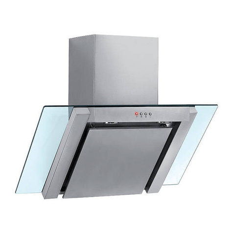
BT46; BT49
INSTRUCTIONS FOR THE INSTALLATION, MAINTENANCE AND USE OF THE HOOD MOD. BT46; BT49
GENERAL
Before installing and/or using the hood, read all the instructions carefully.
Before installing the hood, make sure that the voltage (V) and the frequency (Hz) indicated on the identification plate and all the data inside the appliance are exactly the
same as the voltage and frequency to be found in the place of installation.
IDENTIFICATION PLATE AND TECHNICAL DATA PLATE:
The identification plate and technical data plate are inside the appliance.
INSTALLATION
All the accessories needed for installing the hood are inside the unit.
The hood is convertible and may therefore be installed as an EXTRACTION or PURIFYING hood.
If the hood is used in the EXTRACTION version, connect the opening (diameter 125mm.) (Fig. 1) to an extraction pipe connected directly to the outside, with a minimum
section of 150cm². The bottom of the hood must be at least 70cm above the hob.
IN NO CASE MUST THE HOOD BE CONNECTED TO DISCHARGE FLUES FOR OTHER NON-ELECTRIC APPLIANCES (hot water boilers, heaters, stoves, etc.).
The unit must not be placed above stoves with a radiant top plate.
ELECTRICAL CONNECTION
The hood is intended for fixed and permanent installation. For the line voltage and frequency, see the data plate inside the appliance. The power cable (type H05VV-F
2x0.75mm
2
) connected to the terminals marked L (line) and N (neutral) of the hood and fixed with the cable clamp. Connect the supply lead, if it has a plug, to the power
socket, to allow turning it on or off with the appliance installed, or alternatively to a socket controlled by an omnipolar switch with a contact opening of at least 3 mm.
ONLY FOR U.K.:WARNING:THIS APPLIANCE MUST NOT BE EARTHED. This appliance must be connected by competent person, using fixed wiring via a DOUBLE POLE
SWITCHED FUSED SPUR OUTLET.
We recommend that the appliance is connected by a qualified electrician, who is a member of the N.I.C.E.I.C. and who will comply with the I.E.E. and local regulations. The
wires in the mains lead are coloured in accordance with the following code:
Blue = Neutral, Brown = Live.
As the colours of the wires in the mains lead for the appliance, may not correspond with the coloured markings identifying the terminals in your spur box, proceed as
follows:1) The wire which is coloured blue must be connected to the terrninal marked N (Neutral), or coloured Black.2) The wire which is coloured brown must be connected
to the terminal marked L (Live), or coloured Red (Fig. 6).
The manufacturer declines all responsibility in the event of failure to observe all the accident-prevention regulations in force which are necessary for normal use and regular
operation of the electric system.
TYPE OF OPERATION
Suction operation
Fit the union N to the upper part of the hood using the two screws supplied in a packet inside the packing (fig. 1).
Using a 125mm diameter pipe, connect the union N on the upper part of the hood (fig. 1) to the discharge outlet for cooking vapours with a cross-section of at least 150 cm
2
.
If there is no discharge outlet and the hood is to be fitted to an outside wall of the building, make a hole in the wall that is large enough to fit a wind and rain-proof shutter with
a cross section of at least 150cm
2
and connect this to the outlet union of the unit by means of a pipe.
Air purifier operation
The cooker hood can be converted to work as an air purifier in the event that there is no provision for an external air discharge duct.
In this case air is recycled through the vent R (fig. 1). When using the unit as an air purifier, it is necessary to install two active carbon filters to absorb cooking vapours. The
carbon filters supply is optional. These active carbon filters must be replaced regularly, at least once every three months, to allow normal operation.
FITTING THE ACTIVE CARBON FILTERS
The carbon filters supply is optional.
Press the handle of the metal grease filter towards the rear part of the unit, until it is released from the front housing (fig. 2-A) and remove it by pressing downwards (fig. 2-B).
Fit the active carbon filter O (fig.3a) to the right face of the suction unit, making sure that the holes fit over the dedicated pegs on the suction unit and rotate it in an anti-
clockwise direction until it clamps into place (fig.3a).
Use the same procedure to fit the left filter, rotating it in an anti-clockwise direction.
INSTRUCTIONS FOR ASSEMBLY
The hood is intended for fitting on the wall. Position the hood 70cm above the hob. Remove the metal anti-grease filters (Fig. 2). Position the hood against the wall and mark
on the wall the position of the support holes D and the anchoring holes E (Fig. 4).
Using a drill bit with a diameter of 6 mm, make holes in the wall on the reference marks made previously. Insert the expansion fixings in the holes and then screw the support
screws half-way in. Hook the hood onto the screws and fasten it onto the wall, tightening the support and anchoring screws. Connect the discharge pipe to the coupling N
(Fig. 1). Replace the metal anti-grease filters.
FITTING THE PIPE
Take the two casings A and B: rest the bottom of casing A on the top of the hood. Lift the mobile part B until it reaches the ceiling, checking that it is perpendicular to the
hood. Mark the side measurement of the mobile casing B and then lower it. Take the fixing bracket G (FIG. 4), centre it with respect to the mark made previously, keeping it
in contact with the ceiling, and then mark the anchoring holes H. Using a drill bit with a diameter of 6mm, make two holes on the reference marks made previously. Insert the
expansion fixings provided, put bracket G in position and secure it with the screws provided. Lift casing B up to the ceiling and secure it to the bracket G, inserting the screws
provided in the holes M (FIG. 4).
CONTROL PANEL
The control panel (Fig. 5a) is situated on the front or at the bottom of the hood and comprises:
- a four-position switch for motor control (0 off: 1st - 2nd - 3rd speed) (fig.5a-A).
- a switch for the light (fig. 5a-B).
If the control panel is composed of a push-button panel situated at the front of the hood( fig. 5b), it comprises:
3 buttons for motor control (1st - 2nd - 3rd speed);
1 button for the light;
1 button for switching off the motor.
If the commands panel is made up of electronic commands (fig.5c), consult the attached instructions sheet.
MAINTENANCE
Before performing any operation, always ensure that the omnipolar switch is turned to 0 (OFF).
a) Cleaning
Clean the external parts with non-corrosive liquid detergents, avoiding the use of abrasive powders or of brushes.
b) Changing the light bulb
Before changing the light bulb, ensure that the appliance is not live (the omnipolar switch should be in position 0 - OFF). Remove the metal anti-grease filters (Fig. 2).
Change the incandescent bulb using only olive-shaped spares with an E14 coupling, 40Wmax. If using an electronic bulb, use only spare parts with an E14 coupling,
11Wmax. If using a halogen light, before replacing the light, remove the glass support ring with the aid of a screwdriver. Change the halogen light using only spare parts with
a G40 coupling, 20Wmax. Replace the protective glass and secure it with the ring. If using a 12V dichroic halogen light, use only spare parts with a GU5.3 coupling, 20W
max. If using a 230V halogen light, use only spare parts with a E14 coupling, 50Wmax. Replace the metal anti-grease filters.
c) Changing the carbon filter.
See fitting the carbon filter.
d) Cleaning the metal anti-grease filter.
The saturation of greasy residue in the metal filter may cause increased inflammability. In order to prevent possible fires, the metal filter must be washed regularly depending
on use and at least every three months in a dishwasher or in hot water with normal washing-up detergent. After having carefully rinsed and dried the metal anti-grease filter,
put it back in place.
IMPORTANT
Cleaning must always be carried out according to the manufacturer's instructions, especially as regards the deposits on dirty surfaces which may be a possible fire hazard.
Always take care that the flames or elements are covered so as not to cause overheating of the filter in the hood.
Never leave pans unattended when frying; the oil in the pan may overheat and catch fire. The risk of self-combustion is higher when the oil has been used several times.
It is absolutely forbidden to cook with an open flame under the hood (for example, flambé). The ducted air must not be conveyed into a flue used for discharging the fumes
produced by non-electric appliances; suitable ventilation must also be provided when the hood is being used in environments where other non-electric appliances are
working at the same time. If the non-recycling version of the hood is used, check the conditions of the flue if it has remained unused for a long time.
Remember to pay the greatest attention to the local regulations in force and the requirements of the competent authorities concerning air discharge if the appliance is
operating as an extraction hood. All the advice given here must be scrupulously abided by so as to avoid the risk of fire.
THE MANUFACTURER DECLINES ALL RESPONSIBILITY IN THE EVENT OF FAILURE TO OBSERVE THE INSTRUCTIONS GIVEN HERE FOR INSTALLATION,
MAINTENANCE AND SUITABLE USE OF THE HOOD.


