Baxall CDR Series User manual

CDR Series Cameras
Installation Instructions

CDR Series Installation Instructions
2
This manual is also available in French, German, Italian and Dutch. Please contact Baxall
Ltd, Tel: +44 0) 161 406 6611 or visit www.baxall.com
For details on changing the menu system language, see page 5.
Le manuel est également disponible en français, allemand, italien et néerlandais.
Veuillez contacter Baxall Ltd, Tél: +44 0) 161 406 6611 ou consulter le site Web
www.baxall.com
Pour plus de détails sur le changement de langue, reportez-vous à la page 5.
Das Handbuch ist ebenfalls in Französisch, Deutsch, Italienisch und Holländisch erhältlich.
Bitte wenden Sie sich an Baxall Ltd, Tel.: +44 0) 161 406 6611 oder besuchen Sie
www.baxall.com
Weitere Details zum Ändern der Menüsystemsprache finden Sie auf Seite 5.
Deze handleiding is tevens verkrijgbaar in het Frans, Duits, Italiaans en Nederlands. Neem
voor meer informatie contact op met Baxall Ltd, telefoon +44 0) 161 406 6611 of ga naar
www.baxall.com
Zie pagina 5 voor gegevens over wijziging van de menutaal.
Il presente manuale è disponibile anche in italiano, francese, tedesco e olandese. Contattare
Baxall Ltd, Tel: +44 0) 161 406 6611, oppure visitare il sito web allindirizzo www.baxall.com
Per informazioni sulla modifica della lingua dei menu, vedere a pagina 5.

Installation Instructions CDR Series
3
CONTENTS
Introduction .............................................................................................................. 6
Product Safety ......................................................................................................... 7
Cautions ................................................................................................................... 8
Connectors and Controls ......................................................................................... 8
Power Supply Connection ....................................................................................... 9
Video Connections ................................................................................................... 9
Comms I/ Connections .......................................................................................... 9
Profile Switch Connection ...................................................................................... 10
Lens Connection .................................................................................................... 10
Lens Selection ........................................................................................................ 11
Focus Adjustment ................................................................................................... 11
System Connections .............................................................................................. 12
RS485 Menu Control ............................................................................................. 13
The Menu System .................................................................................................. 16
Entering the Menu System ..................................................................................... 16
Selecting a Language ............................................................................................ 17
Navigating the Menu System ................................................................................. 17
Menu Selection Screen .......................................................................................... 19
Basic Settings Menu
White Balance ........................................................................................................ 21
Gamma .................................................................................................................. 22
AGC (Automatic Gain Control) .............................................................................. 22
Shutter (EI) ............................................................................................................. 23
BLC (Backlight Compensation) .............................................................................. 24
Lens Menu ............................................................................................................. 26
Pk White Menu ...................................................................................................... 27
Camera ID .............................................................................................................. 28
Advanced Settings Menu
Auto Black .............................................................................................................. 31
Video Adjustment ................................................................................................... 32
Info ......................................................................................................................... 33
Restore Factory ..................................................................................................... 33

CDR Series Installation Instructions
4
CONTENTS
Global Settings Menu
Settings .................................................................................................................. 35
Sync Menu ............................................................................................................. 36
Lens Type .............................................................................................................. 38
Comms ................................................................................................................... 38
RS485 Setup .......................................................................................................... 39
Set Passwords Menu
Basic and Advanced Passwords ............................................................................ 41
Password Recovery ............................................................................................... 42
Specifications ......................................................................................................... 43

Installation Instructions CDR Series
5
SÉLECTION DUNE LANGUE
La caméra bénéficie dune option de sélection de langue permettant dafficher le système
de menus en cinq langues différentes.
1. Local: poussez le joystick vers lintérieur
Distant: si vous utilisez un contrôleur de télémétrie, appuyez une fois sur la touche
Autopan. La touche Autopan est désactivée automatiquement lorsquune commande
est envoyée par la suite à laide du joystick du clavier.
2. Entrez le mot de passe suivant - 9 9 9 9. Le menu Langue saffiche.
3. Positionnez le curseur sur la langue requise et appuyez sur la touche de sélection. A
ce stade, un message saffiche pour confirmer la langue sélectionnée.
4. Positionnez le curseur sur SORTIE et appuyez sur la touche de sélection.
SPRACHAUSWAHL
Die Kamera verfügt über eine Sprachauswahlfunktion, die die Anzeige der Menüs in fünf
verschiedenen Sprachen ermöglicht.
1. Lokale Steuerung: Drücken Sie den Joystick nach innen, oder
Fernsteuerung: Wenn Sie eine Telemetriesteuerung verwenden, tippen Sie die
Autopan-Taste einmal an. Die Autopan-Taste schaltet automatisch ab, wenn der nächste
Befehl über die Tastatur bzw. den Joystick gesendet wird.
2. Sie das folgende Kennwort ein - 9 9 9 9. Das Sprachauswahlmenü wird angezeigt.
3. Positionieren Sie den Cursor auf der gewünschten Sprache und drücken Sie die
Wähltaste. Die gewählte Sprache wird dann mit einer Meldung bestätigt.
4. Positionieren Sie den Cursor auf BEENDEN, und drücken Sie die Wähltaste.
SELEZIONE DELLA LINGUA
La telecamera consente di visualizzare il sistema di menu in cinque lingue differenti.
1. Controllo locale: premere il joystick verso linterno.
Controllo remoto: se si utilizza un controller di telemetria, premere una volta il tasto
Autopan. Il tasto verrà disattivato automaticamente al successivo comando inviato
attraverso il joystick della tastiera.
2. Immettere la seguente password - 9 9 9 9. Verrà visualizzato il menu LINGUA.
3. Portare il cursore sulla lingua desiderata e premere il tasto SELECT. Verrà visualizzato
un messaggio che conferma la lingua selezionata.
4. Portare il cursore su ESCI e premere il tasto Select.
EEN TAAL SELECTEREN
De camera beschikt over een taalkeuzeoptie waarin u uit vijf verschillende talen kunt kiezen.
1. Ter plekke: druk de joystick naar binnen, of,
Op afstand: Als u gebruikmaakt van een telemetrieregelaar, dient u eenmaal op de
toets Autodraaien te drukken. De toets Autodraaien wordt automatisch uitgeschakeld
als er de volgende keer via de joystick op het toetsenbord een opdracht wordt verstuurd.
2. Voer het onderstaande wachtwoord in - 9 9 9 9. Het taalmenu verschijnt.
3. Beweeg de cursor naar de taal van uw keuze en druk op de toets Selecteren. Er
verschijnt een bericht dat aangeeft welke taal is gekozen.
4. Beweeg de cursor naar AFSLUITEN en druk op de toets Selecteren.
*These instructions can also be found in English on page 17.

CDR Series Installation Instructions
6
INTRODUCTION
These instructions cover Baxall CDR series cameras. Read all of these instructions. Use
them to install the camera and have them available for its lifetime. If you have any problems,
contact Baxall Limited. ll CDR series cameras are fitted with a Direct Drive (DD) lens
connector, have adjustable back focus and accept C and CS lenses.
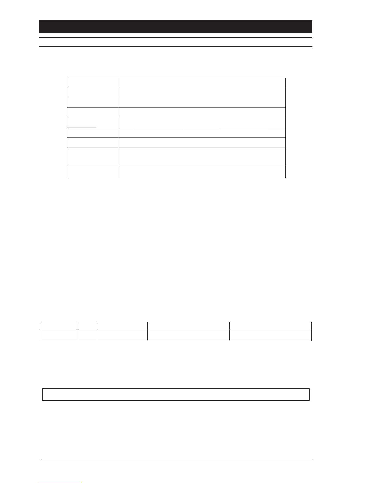
Option
Mono
Color
Resolution (TVL)
Sensitivity (lux @ f1.2)
CCD Sensor size
Sony HyperHAD™ CCD
Sony ExviewHAD™ CCD
580 580 480 48
0
0.1 0.90.04 0.4
1/3“ 1/3“1/2“ 1/2
“
Supply
11 - 40 VDC; 18 - 30 VAC
CDR2233A
CDR4233A
CDR3223A

Installation Instructions CDR Series
7
PRODUCT SAFETY
Installation and servicing is only to e carried out y suita ly qualified and
experienced personnel to local or national wiring standards.
Good engineering practice must e carried out at all times and all servicing and
repairs carried out indoors.
All CDR series cameras are to e powered with a class 2 power supply.
The CDR series camera is fitted with a 1 A time-lag fuse located on the rear
oard assem ly. Replacement must e with an identical type of fuse.
Under no circumstances must the power consumption of the rear Auto Iris
connector exceed 50 mA or the Direct Drive connector exceed 25 mA.
The CDR series range is designed for use in general purpose CCTV applications
and has no other purpose.
Only operate the camera etween the temperatures of -10OC and +50OC.
We strongly recommend that the camera passwords are changed y the installer
as soon as possi le to prevent unauthorised access to the menu system.

CDR Series Installation Instructions
8
CAUTIONS
In order to avoid damaging the camera note the following points.
1) The camera has threaded mounting points on the top and ottom of the case.
Only use a standard, photographic, mounting- olt with a 1/4-20 UNC thread.
2) Before fitting the lens make sure that its ack will not touch the CCD sensor or
associated components when screwed fully home.
3) Do not touch the image-surface of the sensor. If the sensor is accidentally
touched, only clean it using ethyl alcohol.
4) Do not expose the sensor to direct sunlight as this may impair the performance
of the camera.
5) The maximum weight of the camera is 0.55kg.
6) Only use the camera in a clean, dust-free environment.
7) For outdoor use, an appropriate protective housing conforming to IP65 or UL50
or etter must e used.
CONNECTORS AND CONTROLS
(9)(8)
(11)
Side View
Top View
(10
)
(6)
(
1)
(
2)
(
3)
(4)
(5)
(7)
1. External sync input (genlock) BNC
2. Video iris lens connector
3. Low voltage power supply terminals (12 VDC/24 VAC)
4. Composite video output BNC
5. S Video output connector
6. Power LED
7. Comms I/O
8. Joystick (under side flap)
9. DD Lens connector
10. Back focus adjustment screws
11. 1/4 20 UNC mounting bush (fitted
at top and bottom)

Installation Instructions CDR Series
9
POWER SUPPLY CONNECTION
These cameras are fitted with a power supply that operates between 11-40 V DC and 18-
30 VAC. Connections and polarity are indicated adjacent to the terminals on the rear panel.
The power supply must e a class 2 isolated type. The green POWER LED on the rear
panel indicates when power is connected.
Note
This product has an initial current demand on power up of 2 Amps.
VIDEO CONNECTIONS
Composite Video
To obtain a video output connect a video coaxial-cable terminated by a 75 Ohm BNC
connector to the BNC socket marked VIDEO OUT on the rear of the camera.
S-Video
An S-Video output is provided giving a Y/C separated video signal. The 4-pin mini-DIN
connector has the following specification: Y=1V pk-pk, 75 Ohm; C=0.3V, 75 Ohm
Genlock (external synchronisation)
For external synchronisation, connect a video coaxial cable, terminated with a 75 Ohm
BNC connector, to the socket marked GENLOCK on the rear of the camera. The GENLOCK
facility synchronises to either a 1V pk-pk video signal or a standard sync plus blanking
signal. A signal connected to the GENLOCK input automatically overrides all other
synchronisation settings.
Note
When using a master signal to synchronise multiple cameras, only one of the cameras
should have the genlock termination switched on, all the other cameras should have it
switched off. See Sync Menu on page 36.
COMMS I/O CONNECTIONS
1 Ground
2 Ground
3 Luminance
4 Chrominance
1
2
3
4
1
2
3
4
5
6789
1. RS485+
2. RS485
3. 20mA
4. 20mA
5. GND
6. Profile Switch
7. Spare
8. Spare
9. Spare

CDR Series Installation Instructions
10
PROFILE SWITCH CONNECTION
The CDR series cameras have a profile switching feature which allows the camera to be
switched between the settings saved to the Group 4 profile and any other group.
This toggle switch operation is performed by grounding pin 6 of the Comms I/O connector.
When the connection to ground is broken, the camera will return to the group that was
selected before profile switching was enabled.
See Menu Selection Screen on page 19 for more details on saving and restoring group
settings.
LENS CONNECTION
Fixed and Manual Iris Lenses for indoor use only) require no wiring connections.
Auto-Iris Lenses
Connections for auto-iris lenses are located on the rear of the camera. Connect auto-iris
lenses to the 3 terminal connector block according to the table below.
Direct Drive
Connect DD lenses to the female 4 pin socket on the side of the camera. If the lens does
not have a DD plug fitted then wire the lens to a suitable plug in accordance with the
diagram below.
1 = Damp
-
2 = Damp
+
3 = Drive
+
4 = Drive
-
1
3
2
4
DD Lens Connector
Note
When using DD lenses, the ferrite core supplied with the camera must be fitted to the lens
cable as shown below:
Under no circumstances must the power consumption of the rear Auto Iris connector
exceed 50 mA or the Direct Drive connector exceed 25 mA.
Connector Description
Red Lens positive supply
Black Lens ground
White Video drive signal

Installation Instructions CDR Series
11
LENS SELECTION
Suitable lens types are C or CS mount in fixed-iris, manual-iris, auto-iris or direct-drive
versions. Sizes are shown below. Cameras are factory set for CS mount lenses. If using a
C mount lens, rotate either of the back focus screws approximately 30 turns anticlockwise
before fitting the lens.
Lens size
1/3"
1/2"
2/3"
1"
C
D
R
2
2
3
3
A
C
D
R
3
2
2
3
A
C
D
R
5
2
2
3
A
FOCUS ADJUSTMENT
Turn the back focus adjuster screw clockwise or anticlockwise to obtain focus. When the
focus is sharp, turn the adjustment screw 2 or 3 turns anticlockwise. The picture will lose
sharpness. Turn the screw clockwise until focus is once again obtained. If the point of best
focus is passed, repeat the procedure. The last turn of the back focus adjustment screw
must always be in a clockwise direction. Do not over turn or force the back focus
mechanism.
Fixed Lenses
Set the lens focus to infinity and view an image greater than 2 metres away. Focus the
image using the back-focus screw. Set the lens focus as required.
Manual Iris Lenses
Open the iris fully and set the lens focus to infinity. View an image greater than 2 metres
away. Focus the image using the back-focus screw. Set the lens focus and iris as required.
uto-Iris and Direct Drive Lenses
Fully open the iris by covering the lens with a suitable neutral density (ND) filter. Set the
lens focus to infinity. View an image greater than 2 metres away. Focus the image using the
back-focus screw. Remove the ND filter and set the lens focus as required.
Zoom Lenses
Set the lens focus to infinity and fully open the iris by covering the lens with a suitable
neutral density (ND) filter. Zoom out to the widest field of vision and view a distant object.
djust the back focus screw until the object is in focus. Next, zoom fully in and adjust the
focus of the lens until the object is again focused. Repeat these steps until the full zoom
range may be viewed with the minimum loss of focus.

CDR Series Installation Instructions
12
This system comprises a telemetry
controller, receiver and pan/tilt head. The
camera is connected to the monitor via a
telemetry controller e.g. ZTX3). The receiver
is connected to the camera via a 20mA
twisted pair connector. The receiver controls
the pan/tilt head conventionally using
telemetry commands issued by the telemetry
controller. Camera setup can be made via
the built-in joystick or remotely using the
telemetry controller.
Camera
P
/T Head
Monitor
Connection with controller,
receiver and pan/tilt head
Receiver
video
telemetry
20mA T.P.
Telemetry Controller
The camera is connected to the monitor via
a telemetry controller e.g. ZTX3). Camera
setup can be made via the built-in joystick
or remotely using the telemetry controller.
The camera is connected directly to the
monitor. Camera setup must be made via
the built-in joystick.
Camera
Simple direct connection
video
Camera Monitor
Connection via telemetry controller
Telemetry Controller
video
telemetry
SYSTEM CONNECTIONS
CDR series cameras receive coaxial telemetry via the Video Out BNC connector. These
telemetry signals are passed to a receiver when required via a 20mA twisted pair connection.
In normal operation, the camera is completely transparent to telemetry commands and
simply forwards them to the receiver. However, when the cameras menu system is being
accessed, telemetry commands are no longer passed to the receiver and are instead used
to issue program instructions to the camera.
Note
When using coaxial telemetry, the PROTOCOL option in the Comms menu must be set to
COAX. This operation can only be carried out locally via the camera joystick. For more
details, see page 38.
The camera can be connected in a variety of options as shown below:

Installation Instructions CDR Series
13
SYSTEM CONNECTIONS
Notes
When using DC continuous rotation Pan/Tilt heads, two slip rings will be required for
the 20mA twisted pair connection.
Use Belden 8723 or similar for the 20mA twisted pair cable. The screen must be
earthed and the cable length should not exceed 20m.
The recommended coaxial cable is RG59, copper cored. Maximum length is 500m.
RS485 MENU CONTROL
The camera can be connected to a PC-based controller via a BAXCOM or equivalent
RS485/RS232 converter. The controller can then be used to make menu selections.
The connections should be made through pins 1 and 2 of the Comms I/O Connector - see
Comms I/O Connections on page 9 for pin-out.
Notes
The RS485 connections are only used for controlling the on-screen menus. It cannot
be utilized without setting the PROTOCOL option in the Comms menu must be set to
BAXALL. This operation can only be carried out locally via the camera joystick. For
more details, see page 38.
For details on BAXCOM, refer to the online manuals section of Baxalls website.
This product does not incorporate termination or biasing within the RS485 control.
RS485 Menu Control
BAXCOM or
RS232/RS485
Converter
Camera
PC-based
Controller
RS232
RS485
CDR Series Installation Instructions
14
Ta le 2 - Header Bit Format
Fie d Bit Meaning When C eared When Set
Command 7 Message Type Simple Command Format Special Command Format
Ta le 1 - Message Format
Type Va ue
Start Marker 0x02
Address RS485 Address
Command See Ta le 2, Ta le 3 and Ta le 4
Data Field 1 See Ta le 2, Ta le 3 and Ta le 4
Data Field 2 See Ta le 2, Ta le 3 and Ta le 4
Data Field 3 See Ta le 2, Ta le 3 and Ta le 4
Checksum Arithmetic value of all preceding values to make the
line up to zero
End Marker 0x03
RS485 MENU CONTROL
Command Format
The RS485 camera commands consist of a six-byte data stream for all functions comprising
of the information shown in Table 1 below:
Start Marker - This value marks the start of the data packet. It will always be 0x02 ASCII
STX) and will always be the first recognised byte for the message packet. Since all the
messages packets are of fixed length, there is no requirement for a length byte.
Address - This byte contains the destination node for the command packet. A camera will
only accept commands intended for it. A camera will become active on receipt of its address,
and will remain active until receipt of a complete command.
Command - The Command byte contains a bit that determines whether the values in the
succeeding fields refer to simple control functions or special commands. When sending
simple control commands, the Commands and Data 1 fields are combined as two Command
fields to provide the complete message.
Table 3 lists the usage of the bits within the basic command format, whereas Table 4 shows
the commands for other control functions.
Checksum - This is the arithmetic sum from the following equation. It makes the entire line
equate to zero for validation purposes.
Camera Address + Command + Data Fie d 1 + Data Fie d 2 + Data Fie d 3 = Checksum
End Marker - This value marks the end of the message packet and will always occur in this
location in the message stream. The Value will always be 0x03 ASCII ETX).

Installation Instructions CDR Series
15
RS485 MENU CONTROL
General Control Commands
Table 3 shows the general control commands used in the basic command format.
Special Control Commands
Table 4 shows the special control commands that can be used.
Ta le 4 - Special Commands
Specia Command Command Fie d Data 1 Fie d Data 2 Fie d Data 3 Fie d
Day/Night Toggle 0x85 0x00 0x00 0x00
Activate Menu 0x87 0x4d (ASCII M) 0x00 0x00
Menu Enter Key 0x87 0x0d 0x00 0x00
Menu Cursor Left
Menu Cursor Right As detailed in Ta le 3
Menu Cursor Up
Menu Cursor Down
Ta le 3 - Basic Command Format
Fie d Bit Meaning Active When
Command 7 Simple Commands Clear
6 Unused Always Clear
5 Unused Always Clear
4 Unused Always Clear
3 Down Up Clear
2 Up Down Clear
1 Right Left Clear
0 Left Right Clear
Data Field 1 7-0 Unused Always Clear
Data Field 2 7-0 Unused Always Clear
Data Field 3 7-0 Unused Always Clear

CDR Series Installation Instructions
16
THE MENU SYSTEM
CDR series cameras utilise a menu system to facilitate setup and adjustment. The menu
system is password protected by means of a four digit number to prevent unauthorised
tampering and has two levels Basic and Advanced. It is important that the installer sets up
both a basic and an advanced password as until this has been done, access to the menu
system will be unrestricted. For more details on setting up passwords, see page 41.
Once the password scheme has been implemented, it provides access to the Basic level
or both the Basic and Advanced levels. The top level menu hierarchy is shown below.
PASSWORD
ADVANCED
SETTINGS
BASIC
SETTINGS
SAV
E
& EXIT
GLOBAL
SETTINGS
SET
PASSWORDS
RESTORE
SETTINGS
LANGUAGE
SELECTION
A special password is used to access the Language menu, where the language in which
the menu system is displayed can be selected. See Selecting a Language on page 17.
ENTERING THE MENU SYSTEM
Entering the password
To enter the menu system, a password providing access to the Basic Settings menu or the
Advanced Settings menu must be input by the user. Note that entering a password to
access the Advanced Settings menu will automatically provide access to the Basic Settings
menu. The manner in which the password is entered depends on whether the camera is
being controlled remotely or locally using the built-in joystick.
1. Local: Press the joystick inwards, or,
Remote: If you are using a telemetry controller, press the Autopan key once. The
Autopan key will switch off automatically when a command is next sent via the keyboard
joystick.
2. The screen shown below will appear:
PASSWORD ENTRY
* * * *
USE ARROW KEYS
PRESS SELECT WHEN DONE

Installation Instructions CDR Series
17
ENTERING THE MENU SYSTEM
Note that the first digit of the password is selected. To enter the password, the up/down
arrow keys or joystick are used to select the required number for each of the four digits in
the password. An up/down movement of the arrow keys or joystick will cause the selected
digit to either increment or decrement. When the digit is correct, use the left/right arrow
keys or joystick to move to the next digit of the password. When all four numbers have
been correctly set, press the select key and the screen shown below will be displayed. The
system permits three attempts at entering the password before exiting menu mode.
SELECTING A LANGUAGE
The camera features a language selection option which allows you to view the menu system
in five different languages.
1. Following the directions under Entering the Menu System on page 16, enter the
following password:
9 9 9 9
2. The Language menu is displayed.
3. Move the cursor to the required language and press the select key.
At this point, a message is displayed confirming which language has been selected.
4. Move the cursor to EXIT and press the select key.
NAVIGATING THE MENU SYSTEM
The menu system is navigated either directly from the cameras built-in joystick or remotely
via a telemetry controller. The camera responds to five commands namely, Scroll up,
Scroll down, Previous, Next and Select. These correspond to the built-in joystick as shown
below:
Joystick
These same commands may be issued via a remote telemetry controller according to the
table on the next page.
LANGUAGE
ENGLISH
FRANCAIS
DEUTSCH
ITALIANO
NEDERLANDS
EXIT

CDR Series Installation Instructions
18
Product Scroll Up Scroll Down Previous Next Select
ZTX3 Up key Down key Left key Right key any Zoom key
ZTX4 Up key Down key Left key Right key any Zoom key
ZTX5 Up key Down key Left key Right key any Zoom key
ZTX6Up key/joystick Down key/joystick Left key/joystick Right key/joystick any Zoom key
ZMX IT Up key Down key Left key Right key any Zoom key
ZMX Storm Up key Down key Left key Right key any Zoom key
ZMX Plus Up key Down key Left key Right key any Zoom key
Vista Ultra MPX Up key Down key Left key Right key any Zoom key
Vista GEM 3 MPX Up key Down key Left key Right key any Zoom key
Vista Columbus Up key Down key Left key Right key any Zoom key
Using keyboard ZKX2 or similar. Telemetry must be enabled see the keyboard manual
for details).
Telemetry must be enabled for correct operation see the product manual for details).
NAVIGATING THE MENU SYSTEM
A typical menu screen is shown below. The cursor shows the currently selected menu
item and is represented by a box which is moved up or down with the up/down joystick or
arrow keys. The left/right joystick or arrow keys are then used to change the selected
parameter for that menu item. A menu item with an arrow ð), indicates that a sub-menu
exists. Pressing the select key, either the built-in joystick or any of the zoom keys for a
remote telemetry controller), will reveal the submenu. Highlighting EXIT and pressing select
will return to the previous menu level.
Currently selected
menu item
Currently selected
parameter
Indicates submenu
Change selected paramet
er
M
ove up or down
BASIC SETTINGS
WHITE BALANCE USER
GAMMA 0.45
AGC OFF
SHUTTER (EI) EI ON
BLC OFF
LENS MENU
PK WHITE MENU
CAMERA ID
EXIT
Saving changes
Any changes made whilst within the menu system must be saved before the menu system
is exited. This is achieved from the Menu Selection Screen by highlighting the SAVE &
EXIT option. You are then asked to choose a group to save the settings. If you do not wish
to save your changes, select the EXIT option.

Installation Instructions CDR Series
19
MENU SELECTION SCREEN
This is the first menu displayed to the user when the menu system is entered.
BASIC SETTINGS
Selecting this item opens the Basic Settings menu.
ADVANCED SETTINGS
Selecting this item opens the Advanced Settings menu. Note that this item may be disabled
if your password does not allow Advanced user privileges.
GLOBAL SETTINGS
Selecting this item opens the Global Settings menu.
SET PASSWORDS
Selecting this item opens the Set Passwords menu from which you can set the passwords
that are used to access the Basic and Advanced menus.
RESTORE SETTINGS
Changes made in the menu system may be saved to one of four groups by selecting the
SAVE & EXIT menu option. The RESTORE SETTINGS option is used to restore the settings
from one of these previously saved groups. When chosen, you are asked which Group you
want to restore GRP 1, GRP 2, etc.).
The GRP 4 profile is reserved for use with the profile switch feature see page 10). This
group can be accessed for adjustments by using the RESTORE SETTINGS option, however
upon exiting the menu system, the camera will revert to operation in the previously selected
group.
It should be noted that whenever camera power is lost, the settings saved to GRP 1 will be
initially displayed. If you want to return the camera to the settings stored in GRP 2, 3 or 4,
you will have to restore them first using this RESTORE SETTINGS option.
SAVE & EXIT
Selecting this option allows you to save any settings you have made within the menu
system. When chosen, you are asked which Group you want to save the settings to GRP
1, GRP 2, etc.). You can restore saved settings using the RESTORE SETTINGS option.
EXIT
This option allows you to exit the menu system without saving any changes.
MENU SELECTION
BASIC SETTINGS
ADVANCED SETTINGS
GLOBAL SETTINGS
SET PASSWORDS
RESTORE SETTINGS
SAVE & EXIT
EXIT

CDR Series Installation Instructions
20
BASIC SETTINGS MENU
This section covers the Basic Settings menu system
BASIC SETTINGS
WHITE BALANCE ðUSER
GAMMA 0.45
AGC OFF
SHUTTER (EI) EI ON
BLC OFF
LENS MENU
PK WHITE MENU
CAMERA ID
EXIT
Other manuals for CDR Series
1
Table of contents
Other Baxall Security Camera manuals


