manuals.online logo
Brands
  1. Home
  2. •
  3. Brands
  4. •
  5. Baxi
  6. •
  7. Boiler
  8. •
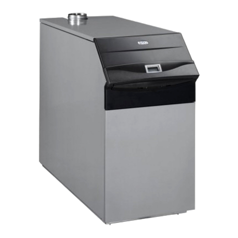
  9. Baxi Slim HP User manual

Baxi Slim HP User manual

1
Slim HPSlim HP
Slim HPSlim HP
Slim HP
Réf. : BAXI - 1373 - I - EN - 0 - 09 / 04
Installer instruction Set
Die cast high yield boiler
Ionisation and electronic ignition check
Fume safety thermostat
83 / 99 / 116 kW
2
Contents
1 General
2 General specifications
3 Installing the boiler
4 Installing the boiler
5 Maintenance
6 Refitting the heating unit (in case disassembly on site)
5 CC 170 control module
3
1 General
1.1 Description of the boiler
Theboilershaveaheatingbodyincastiron,anatmospheric
gasburnerwithdualratingtotal premixandelectronicignition
usingan intermittent pilot burner
Therange proposes 4powers, from 66 to 116kW.
These boilers are supplied with a control panel fitted with
either:
Theseboilersaredeliveredwithacontrolmodule
Theseboilersaredeliveredassembled
1.2 Directives and Standards
Theseboilersare CE certified incompliance with European
directives:
- EN656
- Gasdevices 90/396/CEE
- Yields 92/42
- Electromagneticcompatibility 89/336,
accordingto standards EN500 81-1, EN 50082-1
- Theboilers are type B11(B11BS proposed in option)
- Lowvoltage" 73/23
Designed to be used in a heating circuit with hot water at
maximumtemperature of 90 °Cand a pressureof 5
bar.
The installation and maintenance of the device must be
ensured by a qualified professional, in complance with
currentlyenforcedregulations and rulesofthe art.
1
3
GAS 2
4
5
N03891.DSF
BAXI waiveranyliabilityforany damagesresulting
from work not complying with this manual or
performed by non qualified persons.
1.3 Operating principle
Controlcycle
Uponcommissionning,the1st flapofthemaingasvalve(1)
opensandanignitor(2)ensurestheautomaticignitionofthe
ignitor burner (3) (intermittent pilot burner) with a flame
monitoredbyanionisingprobe,whichremainslitconstantly
duringthecommissionningofthemainburner(4).Thesetis
controlled by a contoller unit authorising the opening of the
mainvalve(1)andauxiliaryvalve(5)(for7and8elements).
Duringregulation,thesafetydevicesareself-checkedbefore
ignitionofthemainburner,byshortstoppageandrestarting
oftheignitionburner.
Operation:
- themainvalvehasareducedrating(1st rating),factoryset
to 60% nominal rating (2nd rating).
- theboiler’sthermostathastwostages(60%and2nd rating
100%)
- whentheboiler’stemperaturereachesthesetpoint ofthe
2nd rating,themainvalveswitchestoreducedrating.Ifthe
temperature reaches the setpoint of the 1st rating, the
thermostatstopstheburner’soperation.
- Thetemperaturedifferencebetweenthe1ststagesetpoint
and the 2nd setpoint is 10 °C.
The boilers are fitted to operate with natural gas
group G 20 - 20 mbar. For any gas change see
chapter 4.4.
BAXI certify compliance of all boilers mentioned in
this manual in reference to the appliances of the
correspondingtypes,havingtherightsofuseofthe
EC Marking according to the European Directives
for "Gas appliances" and "Boiler yields".
4
2 Generalcharacteristics
2.1 Characteristicsofthegas
N05439-EN.XLS
CE Nr
B11BS
kW 52.9 72 90 108 126
60% kW 31.7 43 54 64.8 75.6
kW 48.7 66.2 82.8 99.4 115.9
60% kW 29.2 39.7 49.7 59.6 69.5
45678
G20 5.7 7.6 9.5 11.4 13.3
G25 6.6 8.9 11.1 13.3 15.5
60%
100%
60%
100%
°C 135 128 134 148 125
% 55.9675
kg/h 154 191.4235.4243.2358.7
Flow rate
15°C 1013 mbar 4.2 5.6 7 8.4 9.8
60%
100%
Ø 0.3
Injector mark 215 Y
G31 Design rate (Qn)
Pressure at
injectors mbar 14.5
35
Fumes temperature
CO2
Fumes flow rate atdesign rate
Propane
gas 37
or 150
mbar
Øpilotburner injector
G25 Pressure at
injectors mbar 6
16.5
Injector mark 350 W
6
16.5
Injector mark 320W
7
Number ofburner injectors
Natural
gas
20,25 or
300 mbar
Øpilotburner injector Ø 0.5
Flow rate m3/h
15°C 1013 mbar Design rate (Qn)
G20 Pressure at
injectors mbar
3456
Design useful power
Low rate useful power
Number of elements
Number of burners
Type coffume duct B11
Design heatflow rate
Low rate heatrate
1312BS5053
Category II 2Esi 3P
5
2.2 Maindimensions
R Tapered outside threading
Rp Cylindrical inside threading
Service pressure: 5 bar
Power supply 230 V 50 Hz
Max operating temperature : 90 °C
N05496-EN.TBL
874
N05440-1.DSF
A
1004
D
143
243
485
807
60
Ø F
880
C
B
1190
45 51
263
874
Bleed tap
Ø 1/2
Inlet of
gas
Backflow
Outlet
Number elements 4 5 6 7 8
Sizes in mm
A 456 537 612 699
B 1080 1100 1160
C 965 975 1000
D 1003 1013
Ø F (outside) 182 202 252
Ø blackflow Rp 1" 1/4 Rp 1" 1/2
Ø outlet - inlet of gas R 1" 1/*4 R 1" 1/2
UP to Ut 15 in mbar 12 22 31 41 53
Liters 25 30 35 40 44
Weight 240 285 330 375 415
6
3.2 Hydraulicconnection
Connectiontotheheatingcircuitisperformedatthebackof
theheater.Connectingthefacilitytothewatermainsmustbe
performedaccordingtocurrentlyenforcedrulesoftheartand
regulations, and using a CB disconnector to fill the heating
circuit. For networks with a hardness exceeding TH 20, we
recommend installing a treatment system.
The boilers feature a modern design, their low momentum
enablesthemtoadapttoregulationdemandatanytime.With
a low water content, they require a clean circulation
water, imposing the following precautions before
connecting the boiler
- Newinstallation:Performawashing, then a rinsing, under
pressure.
- Old installation:Ask a specialist to perform a “descaling -
declogging”procedure,followedwithrinsing.
RECOMMENDATIONS:
Never fill a hot boiler with cold water. Sudden cooling
canresultinbreakagesduetothermalconstraintsinthe
cast iron block.
Connect the boiler by inserting on the backflow a
dynamic drip, adapted to the flow rate, with periodical
bleed setpoint.
IRRIGATIONOFTHEBOILER
Thefacilitymust be calculatedtoensureawaterflow inside
the boiler reaching a ∆T included between 10 and 20 K.
In case of a sudden interruption of the water flow,
the safety thermostat triggers total stoppage of
the boiler, and requires rearming.
The facility’s design must ensure sufficiently gradual
regulation to comply with the response times of the
thermostats.
F
01454
In this same room, storage of flammable products is
strictly forbidden.
Any partition sensitive to heat must be protected
using appropriate insulation.
3 Installing the boiler
3.1 Fitting the boiler
The boilers are designed to be installed without a base, on
the floor of the boiler room, provided it is flat, sturdy, dry
andincomustible.
Otherwise,refertothe base drawing below.
Never seal the boiler’s feet (free expansion).
Comply with the panel dimensions as the minimum space
aroundthe heater forconnecting the water and gas circuits
andformaintenance.
Heatingoutlet
Heating backflow
Gas inlet
Bleed tap
Number elements 5 6 7 8
F mm 364 445 526 607
Irons
optional
sealing
Rear
Front
300 700
N05442-1.DSF
200 100
N05441-1.DSF
N05443-1.DSF
7
01455-01
D
R
01304-01
R
D
01459-01
R
D
3.3 Hydraulic connection diagrams
IMPORTANT: The hydraulic connection diagram of each
installation must be determined together with the
correspondingregulation.
D Outlet facility
R Backflowfacility
Stopvalve
Valve rated at 4 bar max
Recommandedrecyclingpump
Muddrainvalve
Checkvalve
Expansiontank + pressure gauge - bleed
Boiler
Boiler
Outlet
Backflow
Outlet
Backflow
Outelet
Boiler
Backflow
Boiler
Outlet
Backflow
Boiler
Outlet
Backflow
Settingvalve
Decantationdripdynamic
3-channelvalve
Primarypump
SHWloadpump
SHWexchanger
Condenser
3.4 Gasconnection
Thegasconnectionisensuredontherearleftoftheheater.
3.5 Connection to chimney
- the draft hood includes a vertical female outlet duct to
which is connected the fume duct with the dimensions
indicated(seechapter«generalcharacteristics»).
- the calculation of the fume duct must comply with the
currentlyenforcedregulations.
- place the boiler in the boiler room, ensuring the burnt gas
path to the chimney is as short as possible. The vertical
section of the duct above the draft hood must be as long
aspossible before fitting anelbow.Theextraction
measured(see diagram below), mustnot be below 0.8
mm CE nor exceed 3 mm CE (the boiler must be
operating).
- the burnt gases duct must be secured carefully and
must not be supported by the boiler. We recommend
installingaremovableduct.
N05441-1.DSF
03004-01
The position for measuring
the extraction is equal to
the Ø of the chimeney
1 meter
minimum
recommanded
8
Connect the phase to the strip’s L terminal.
Theline must withstandanintensityof6.3A under230V50
Hz+Ground(checkthatpowerofthepump(s)iscompatible).
Implementtheelectricconnectionasshownintheelectrical
diagramoftheinstructionset.Fitagroundwire50mmlonger
than the neutral and Phase wire to ensure tear-out safety.
The burner switch fitted on the regulation module does not
dispense with the need to fit the regulatory wall switch.
Inthecaseofinsufficientionisingcurrentduetononcompliant
neutral or ground, we recommend adding a circuit isolation
transformer with a power at least equal to 600 VA.
Control panel supply connection terminal strip
Cable paths
Avoid any contact between the sypply cable and the
drafthood.
Passage of the
supply cable
N05446.JPG
Installation diagram recommended
Table:Calculationofthefumeductsforconnectingtwo
identical boilers
3.6 Room ventilation
Theboilermustbeinstalledinaroomproperlyventilatedand
separatedfromthelivingquarters.Theorificesmustalways
bemaintainedingoodconditionofoperation,theymustallow
forminimumventilation.
3.7 Electricconnection
Thefacilitymustcomplywithcurrentlyenforcednationaland
localregulations.Notably,theelectricconnectionoftheboiler
requiresasectioningdeviceoneachpolewithaminimum3
mm distance between each contact.
Thepowersupplyterminalstripisaccessibleafterremoving
thetop(see§5.1A-B).Itislocatedinthetopleftangleofthe
regulationbracket(oppositetheboiler).
Nr
of
elements
Power in
kW
1 boiler
Power in
kW
2 boiler
Dimensions in mm
Ø
connection Ø
collector duct Ø
fumes
5 66.2 132 180 300 300
6 82.8 166 200 300 300
7 99.4 200 200 300 300
8 115.9 532 250 300 300
Nr of elements Power in kW Ventilation cross-section (cm²)
low high
5 66.2 290 * boiler room
surface
(m²) x 10
6 82.8 360
799.4435
8115.9510
* minimum high ventilation cross-section = 150 cm²
Theground socket plannedon the connectingtermi-
nalstripmustbeconnectedaspercurrentlyenforced
provisions.
1m
N05444-1.DSF
connection Ø
collector Ø
fume duct Ø
N05445-00-1.TIF
Main power
supply
230 Vac 50 Hz
(phase imperatively
in L)
Connection of a
room thermostat
if any Heatingpump
supply
9
Thermostat and
thermometer bulbs
02078-01
00229-5
Boiler glove finger
with regulation probe
When fitting the capillaries, ensure they are inserted fully
in the glove finger.
1 - Overheating safety thermostat
2 - Heating outlet thermometer
3 - Regulation thermostat
4 - Tube Ø 6
Main valve
dual rating
(9-channel connector)
Ignition transformer -
Gas pressure switch
(6-channel connector)
Connecting
additional valve
(conenctor
3 channels)
Ignitionplug
Plug
ionisation
Glove
finger
glove
finger
Main valve
dual rating
(9-channel connector)
Ignition transformer -
Gas pressure switch
(6-channel connector)
Ignition
plug
Plug
ionisation
Glove
finger
glove
finger
4 Commissionningtheboiler
4.1 Connectionwithcomponents
Electricaly connect the control module and the various
components:
- Ignitiontransformerandgaspressureswitch(connector,
6channels),
- dualratingsmainvalve(9-channelconnectors)
- additionalvalve(3-channelconnector)
- connectingtheignitioncable(leftelectrode)andionisation
cable (right electrode) on the intermittent pilot burner
assembly.
- fittingthethermostatbulbs,thermometer(andregulation
probeinoption) in the glove fingerasshown in the
diagram.
Connecting 1 valve
Connecting 2 valves
N05448-1-.DSF
N05449-1.DSF
Thermostat and
thermometer bulbs
10
Descriptionand setting of thepressure:
- model6 elements are fittedwith a single gasvalve.
- modelswith 7 and8 elements arefitted with two valves
fittedin parallel.
- themain valveincludesadualstage regulatorusedtoset
the pressure at the injectors for nominal rating (screw A)
andminimum rating (screw B).
- the2nd valve(complementaryvalve)isasinglestage
valvewitha regulatorwhichmustbelocked.
Model 6 éléments
Models with 7 and 8 elements
03883-00
A
B
C
Thegasramp- burner set is factorysetdor design pressure
andreduced pressure (see gascharacteristic page 4).
Ifamodificationoftheinjectorpressure is required, proceed
asfollows:
- loosen the pressure screws at the injectors located on
the gas ramp and check the pressure with a pressure
gaugeattheappropriatepressure.
Settings and checks
- firstset the design pressure, then the minimum pressure.
- any adjustment of the nominal pressure impacts the
minimumpressure setting.
- neverserthedesignpressureabove the range indicated.
Before commissionning, check the compliance of
the burner equipment with the supply gas.
IMPORTANT: The settings must be made only by
skilledstaff
Wait for the pressure to stabilise before adjusting.
We recomment activating the dual stage regulator
several times to ensure proper setting.
The hood must be removed before performing the
settings.Inordertodothis,insertasmallscrewdriver
in one of the notches, and remove the cap slowly.
ADesign pressure setting screw
BMinimum pressure setting screw
CCap
Setting the adjustment screw for maximum pressure level
Setting the adjustment screw for minimum pressure level
11
4.3 Commissionning the boiler
Refertotheuserinstructionsetoftheboiler
4.4 Adaptation to another gas
The gas changeover operations must be performed
by a skilled professional.
The boilers are supplied for operation using G 20
natural gas:
G 20 (300 mbar) - kitN° 1.7405.519(regulator)
In case of changeover to «Propane» gas, use one of
the following kits:
G 31 (50 mbar) - kitN°1.7405.541 (injector)
G 31 (150 mbar) - kitN°1.7405.541(injector)
+kit N° 1.7405.519 (regulator +
spring)
Theboilersaresuppliedfactorysetforusingnaturalgastype
G 20, with the kit matching the customer’s request.
For applications with Propane 50 or 150 mbar (see gas
characteristics in page 4), il you have to replace or else
changethefollowingelements:
- mainburnerinjectorsmark215Y
- pilot burner injector Ø 0.3
Main valve:
(see gas settings page 10)
- screw A tightened to max
- screw B set to 22 mbar
For models with 7 and 8 elements, the 2nd valve
(complementary) is a single stage valve with a locked
regulator.
12
5.1 Removing the panels
1ALiftthestoptabsatthebackofthe
boiler
BSlidethetoppaneltotherearand
lift it
CRemovethe2fasteningscrewson
thefacade
DLiftthefacadeupwardsandpullit
towardsyou
A
1
N03923.DSF
B
D
C
•
N05450.JPG
N05451.JPG
N05452.JPG
5 Maintenance
Theguaranteeconditionsrequiretheoperation,preventiveandcorrectivemaintenanceoftheboilerperformedsatisfactorily.
Regularmaintenanceperformedbyprofessionalswillensuresafeoperationandlonglifeoftheboiler.
Therefore,amaintenancecontractmustbeunderwrittenwiththecompanyhavingperformedtheinstallationoracompanycertified
for taking on such a contract.
Forthesamereasons,theoperatingmanualoftheboilerwillbeprovidedbytheinstallertothepersonsinchargeofoperation,
withalltheinformationrequiredformanagingtheinstallation.
Thesweepingandmaintenanceoperationsmustbeperformedbyaskilledprofessional.BAXI waiversanyliability
for damage resulting from work performed by non qualified staff and lack of compliance with these instructions.
13
A
B
3
B
2AUntighten the M5 screws on the
controlbracketwithout removingthem,
lift and pull towards you.
If required, disconnect the connectors,
thesupplycable,andremovethebulbs
fromthesensorpocket(referto§4page
9)
3ARemovethe gasinletbracket
BUntighten the M 5 screws on the
leftandrightpanels,atthebackandfront
oftheboiler
CRemovethe2screwsofthedrilled
plate at the front of the right and left
panels
A
2
N05453.JPG
C
14
230 V - 50 Hz
4
D
E
03639.dsf
C
B
A
5.1 Removing the burner
5disconnectthe power supply.
Close the gas protection tap
Remove the top, front panel and 2
removablepanels(referto§5.1A-B-C-D
page12)
ADisconnect the control module
fromthevalves
Bunscrew the gas valve union nut
(bewaretheflatgasket)
Cremovethebottomsheet
Dunscrewtheburnerplatelongnuts
ETpull the burner assembly
horizontally
Checkthecondition of the burner’s sur-
face,cleantheburner,
Check the positioning and condition of
theelectrodes(seediagram).
Before refitting the burner, perform
the sweeping (see § 5.3 page 15)
Electrode
ground
Electrode
ignition
Ionisation
electrode
Top view
15
5.3 Sweeping
We recommend performing at least
once per year a sweeping of the
heating body.
Removethetoppanel(referto§5.1A-B
page12)
6ARemovethedrafthoodflap
BEngage the sweeping brush
betweenthe finsvertically,inthe axisof
the gas chimneys
Refit the draft hood flap and check the
sealing
Refitthetoppanel
After these operations (burner
disassembly and chimney sweeping :
- checkgascircuitsealingandproper
operation(ignition,pilotflame,control
devices)
- performageneralcheckoftheboiler
(fastening,sealing,properoperation
ofthe gas line and operation of the
thermostats).
A
B
6
16
5.4 Operatingincidents
Boiler does not start - checkthe powersupply isavailableand thatthe orangeindicator
is lit,
- check that the thermostats and regulations are in demand,
- checkthat the overheatingthermostat is not activated,
- pressthe rearmingbutton,restarttheboilerandperform thecomplementary
checks:
• checkcomplianceofthedraftinthechimneyaccordingtotherecommendations
(> 0.8 mmCE i.e. 8 Pa),
• checkcomplianceofthepressureon injectors according to manufacturer
data(seepage4),
If one of these 2 parameters is not compliant, overhaul before restarting
the facility.
- check that the control box is supplied by mains; change if faulty.
Noignitionspark - theignition transformer is not supplied with 230V,
- linkfaultbetweentheignitiontransformerandelectrode,
- short-circuitbetweentheignitionelectrodeandground,
- ignitiontransformeroutofservice.
Spark present but no flame on the - check that the gas supply is open,
intermittentpilotburner - checkthegas pressure onthevalveupstreamconnector,
- check that the pilot burner gas tube is bled,
- check the pilot burner injector,
- checkthe position of theignition electrode inrespectof the ignitionburrner head,
- to restart, press the rearming button.
Flamepresentontheignitionburner - checkthepolaritieswhenperformingtheelectricconnection.The but the phase
control box switches to safety after is connected to the L terminal and neutral to N,
50seconds - checktheionisationcurrent,thenominal value in natural gas of 3 to 4 micro amps,
- check the position of the ionisation electrode,
- bleed the gas tube,
- to restart, press the rearming button.
Noflameonthemainburner - checktheelectric wiring onthevalve,
- check the electric connection to the main terminal strip,
- checktheoperationofthegasvalve,replaceifrequired,
- check the control box, replace it if required.
17
- usingthe samemethod,securethe leftendelement(Fig.5).
- laythe end elementon the ground on the outlet side(left
in the example) at its final location, and check the
centering of the 1st branchingin the «A» flange (Fig. 5).
Theotherendelementispushedtemporarily(~20mm)to
helpfitting the intermediate elements (Fig. 4).
- gluetheglassfibresealingcordsusingtheneopreneglue
suppliedwiththeboiler,inthe front and rear grooves on
onesideofeachintermediateelement.Proceedidentically
fortherightendelement(upperprotrusion)(Fig.6).
- fit an intermediate element supported on the outlet side
endelement and collector. Proceed identically for all
intermediateelements(Fig.7).
Caution:Applyconstantpressureontheendelementinthe
directionofthearrow(fig.8)whileslightlylooseningthe«A»
fitting plate used to pull the last element, and tighten.
- fitthe3assemblyrods(T)andadjustthegapsizeB atthe
frontandthe back (Table and Fig.13).
- fittherearcollector(E) (Fig.9).The centeringpinwelded
on the collector is used to position it precisely, in respect
of its tightening plate (F).
- fit the tightening plate with only 2 nuts at each end.
6 REASSEMBLYOFTHEHEATER
(incase of on-site dismantlingtoreach the boiler
room to follow the following instructions)
6.1 Assembling the heating body
Itis asimpleoperation,provided youscrupulouslyobserve
thesequenceofoperationsspecifiedhere.Priorreadingwill
enableunderstandingtheoperatingmode.
- nospecial tooling isrequired, other thana wooden mallet
(donotuseahammer)andasquare,tohelppositiningthe
elements.
- the elements must be clean and the gasket surface void
of products likely to damage the EPDM gaskets.
- you must have a flat ground (see § 3.1).
ASSEMBLYWITHOUTGASKETS
The heating body is composed of three types of elements:
an end left element (L), intermediate elements (M), and a
right end element (R) (Fig. 1 and 7).
- screwthe studs (shortest threading) inthe tapered holes
of all die cast elements (Fig. 2).
- fittheoutletcollector(D)ontotherightendelementusing
one of the plates (A) (Fig. 3 and 4).
Fig. 9Fig. 8
A
Fig. 11Fig. 10
01468-01
01470
E
F
01470-1
FE01469-02
Fig. 3
Fig. 5
D
R
C
A
L
Fig. 2
Fig. 4
R
A
01464 01465-01
01462
01463-01
Fig. 7
MM
L
Fig. 6
AR
AV
01466
01467-01
D
LR
A
A
01461-01
Fig.
18
FITTINGTHEGASKETS
Pull the cast iron body backflow collector by 15 to 20 mm
usinga lever (chisel- screwdriver). Insertthe gaskets at an
angle,byplacing the base in theslotandthe top against the
collector (Fig. 10 and 11).
- fitthe washers andnuts, then approachthe collector tofit
the gaskets supported, but without tightening.
- BEWARE the resistance of the assemblyrods (T) then,
remove the «A» fitting plates on the Outlet collector, and
fit the tightening plate (G) (Fig. 13).
- proceedidentically asforthebackflow collectorwhenfitting
the gaskets (Fig. 10 and 11).
- the heating body is assembled, but not tightened, so you
can «play» with the body by successive side pushes in
orderto align gaps (Fig. 12).
Check the following for the last time:
a) size B at the assembly rods
b) the positioning of the collectors (centering pin on the
collector)
c) perpendicularitybetweentheBackflowcollectorandthe
elements(Fig. 12).
- ock uniformily the set of nuts on the collectors.
- install the bleed tap in the 1/2" branch of the Backflow
collector.
Fig. 13
B
T
01472-02
HG
H
Fig. 12 01471-01
6.2 Fittingthedrafthoodandfront
inside panel
Heating body sealing check.
Cap Outlet and backflow. Fill with
waterusingthe bleed tap while
bleedingtheair throughtheoutlet
orifice.
CAUTION:Checkpressurising
without exceeding 5 bar on the
pressure gauge. Leave
pressurisedfor 10 minutes.
7AFit the rear panel with its
insulatorbeforethedrafthood
BInserttheheatinsulators
between the water arms at the bottom
ofthefirebox
CApply a dot of silicone (cartridge
supplied)onthe front returnsofthe
elements
DScrew the studs onto the right
andleftelements
N03865.DSF
C
B
D
7
A
CAUTION: To prevent damaging the EPDM gaskets,
do not use mineral glue nor grease. Only the vaseline
supplied can be used in contact with the gasket.
Elements Size B
4
5324
6405
7486
8567
19
8APlacethesealinginsulatingstrips
ontotheboilerblock(onehorizontal,one
vertical,andonefoldedwithasquare)
BPlace the 2 insulating pads on
the right and left end elements
CFit the draft hood on the sealing
strips to ensure it is between the
embossings Dfor fitting elements
EFit the draft hood using the
tighteningplates and ensuresealing is
ok
FFit the front internal wall with its
insulator and secure it with 4 nuts and
washers
6.3 Fitting the burner assembly
9AThe ignition transformer is fitted
on the inside panel with 2 M5 self-
taperingscrews
BFit the burner assembly with 6
longnuts andwashers
CFitthegastubewithagasketand
nut on the gas ramp
DFit the gas tube on the inside
panel using the collar (2 screws and
nuts)
EFitthe water sleeveon the outlet
elbow
FFit the heat insulator around the
drafthood
9
8
C
D
E
B
F
N05455.DSF
A
•••
03203-00
•
A
C
D
E
F
N05456.DSF
B
20
7
CC 170 control
7.1 Description
Over heating safety
thermostat
Burner lock out reset
push button
General switch
On - OFF
Power ON lamp
Burner lock out lamp
Over heating lamp
Thermometer showing
the boiler’s temperature
Fuse
6,3 AT
Safety thermostat test push
button
CC 170
6.3 AT
Pressure gauge
Schématic diagram CC 170
Ignition 1st
stage 2nd
stage
VSC VSB
MST
TR1
STB ZSB
ZG
ZT
ION
DGAI
P-CH
F1
L
N
TR2
DG
V
UX
Y
213 6
4578 910 11 12
213 6
4578
N05457.JPG
N05459.AI
Legend for wiring diagrams
L Live
L1 Heating pump supply
N Neutral
F1 Fuse 6.3A
MST Power ‘on’ lamp
VSC HighLimit Trip Lamp
VSB BurnerLockoutLamp
ZG ON/OFF Switch, with light
ZT Limit Thermostat Test Button
P-CH Boilerpump
STB HighLimit Thermostat
TR1 Low fire control thermostat
TR2 High fire control thermostat
A Terminalblockforboilerpump connection
C Terminalblockforpower supply connection
DGAI Flamecontrol unit
ZSB BurnerReset
ION Ionization
P Presostat(notincluded)

Other Baxi Boiler manuals

Baxi Luna Platinum 1.12 User manual

Baxi

Baxi Luna Platinum 1.12 User manual

Baxi LUNA HT 1.850 User manual

Baxi

Baxi LUNA HT 1.850 User manual

Baxi Power HT Series User manual

Baxi

Baxi Power HT Series User manual

Baxi Bermuda 553 User guide

Baxi

Baxi Bermuda 553 User guide

Baxi 800 Combi 2 Manual

Baxi

Baxi 800 Combi 2 Manual

Baxi Duo-tec Combi HE a Range Instruction Manual

Baxi

Baxi Duo-tec Combi HE a Range Instruction Manual

Baxi 50 HE Plus Release note

Baxi

Baxi 50 HE Plus Release note

Baxi Heat 616 Manual

Baxi

Baxi Heat 616 Manual

Baxi Roca LIDIA GT EM Series User manual

Baxi

Baxi Roca LIDIA GT EM Series User manual

Baxi LINA 3 COMFORT HT User manual

Baxi

Baxi LINA 3 COMFORT HT User manual

Baxi LUNA HT 1.350 User manual

Baxi

Baxi LUNA HT 1.350 User manual

Baxi Solo Innova User manual

Baxi

Baxi Solo Innova User manual

Baxi PREMIER PLUS Series Guide

Baxi

Baxi PREMIER PLUS Series Guide

Baxi Bermuda 45/3 M User guide

Baxi

Baxi Bermuda 45/3 M User guide

Baxi LUNA DUO-TEC 1.70 User manual

Baxi

Baxi LUNA DUO-TEC 1.70 User manual

Baxi MainEco Heat 15 Manual

Baxi

Baxi MainEco Heat 15 Manual

Baxi NUVOLA PREMIX 23 User manual

Baxi

Baxi NUVOLA PREMIX 23 User manual

Baxi Duo-tec Combi 24 HE A Release note

Baxi

Baxi Duo-tec Combi 24 HE A Release note

Baxi nuvola3 comfort Guide

Baxi

Baxi nuvola3 comfort Guide

Baxi Luna Duo-Tec MP Plus 1.35 Guide

Baxi

Baxi Luna Duo-Tec MP Plus 1.35 Guide

Baxi PREMIER PLUS 800L Guide

Baxi

Baxi PREMIER PLUS 800L Guide

Baxi Ecoblue plus combi 24 User manual

Baxi

Baxi Ecoblue plus combi 24 User manual

Baxi 100 He Operation instructions

Baxi

Baxi 100 He Operation instructions

Baxi Maxflow Combi WM User guide

Baxi

Baxi Maxflow Combi WM User guide

Popular Boiler manuals by other brands

Viadrus NAOS K4 manual

Viadrus

Viadrus NAOS K4 manual

Weil-McLain SVF 1500-3000 Series User's information manual

Weil-McLain

Weil-McLain SVF 1500-3000 Series User's information manual

Immergas VICTRIX 24 TT 2 ERP Instruction and warning book

Immergas

Immergas VICTRIX 24 TT 2 ERP Instruction and warning book

Ferroli ENERGY TOP W 80 Instructions for use, installation and maintenance

Ferroli

Ferroli ENERGY TOP W 80 Instructions for use, installation and maintenance

Beretta JUNIOR GREEN C.S.I. Series installer and user manual

Beretta

Beretta JUNIOR GREEN C.S.I. Series installer and user manual

Lochinvar 1 Service manual

Lochinvar

Lochinvar 1 Service manual

Ariston UNO installation instructions

Ariston

Ariston UNO installation instructions

Ferroli ATLAS D 30 Ki 100 UNIT Instructions for use, installation and maintenance

Ferroli

Ferroli ATLAS D 30 Ki 100 UNIT Instructions for use, installation and maintenance

Triad Triumph series owner's manual

Triad

Triad Triumph series owner's manual

Ferroli Xignal Service instructions

Ferroli

Ferroli Xignal Service instructions

Enerzone CAH 33-44-50 Installation & maintenance

Enerzone

Enerzone CAH 33-44-50 Installation & maintenance

Biasi RINNOVA ADAPTIVE 30S User manual and installation instructions

Biasi

Biasi RINNOVA ADAPTIVE 30S User manual and installation instructions

Ariston Clas 24 FF user manual

Ariston

Ariston Clas 24 FF user manual

Laars NTV1700 user manual

Laars

Laars NTV1700 user manual

Hoval CompactGas 700 Assembly instructions

Hoval

Hoval CompactGas 700 Assembly instructions

Ferroli DIVACONDENS D PLUS F 24 Instructions for use, maintenance and installation

Ferroli

Ferroli DIVACONDENS D PLUS F 24 Instructions for use, maintenance and installation

Laars FT Series Installation and operation instructions

Laars

Laars FT Series Installation and operation instructions

COMBOMAX ULTRA Installation use and care manual

COMBOMAX

COMBOMAX ULTRA Installation use and care manual

manuals.online logo
manuals.online logoBrands
  • About & Mission
  • Contact us
  • Privacy Policy
  • Terms and Conditions

Copyright 2025 Manuals.Online. All Rights Reserved.