Baxter Verticut 115 C User manual

B
BA
AX
XT
TE
ER
R
VERTICUT MITERCUT SAW
Model No: 115 C
Serial No:
Operation Manual
W
WE
ES
ST
TW
WA
AY
Y
M
Ma
ac
ch
hi
in
ne
er
ry
y
L
Lt
td
d.
.
“Exclusive Canadian Import Agent”
2370 Cawthra Road, Mississauga, ON L5A 2X1
Tel: (905) 803-9999 Fax: (905) 803-9109
Toll Free 1-800-263-1199
Website: westwaymachinery.com
A
B>qXTER
l/ERTICUf
INC.
BANOSAW
MACHINES
VERTICUT
odel
115C
instruction
Manual
l^ll^mbers:
6429
TO
6433
inclusive
27
Kenhar
Drive,
North
York,
Ontario
Canada
M9L
1M9
(416)
741-7100
fax
(416)
741-7114
www.verticut.com

B>qXTER
ZwA
MERTICUr
Table
of
Contents
1.
Forward
2.
Notes
3.
Safety
Instructions
4.
Machine
Specifications
5.
Machine
Views
5.1.1
Front
View
5.1.2
Left
Side
View
6.
Installation
Instructions
7.
Operating
Instructions
7.1
Electric
Control
7.1.1
Electric
Control
Panel
View
7.1.2
Saw
Operation—Electrical
7.2
Material
Clamping
7.2.1
Work
Table
View
7.2.2
Miter
Block
7.2.3
C-Clamp
7.2.4
Material
Stop
7.3
Saw
Carriage
Movement
7.3.1
Carriage
Handles
/
Foot
Pedal
View
•
7.3.2
Carriage
Handle
7.3.3
Foot
Pedal
7.4
Saw
Operation
7.5
Cutting
Force
7.5.1
Adjust
Cutting
Force
View
7.5.2
Cutting
Pressure
Adjustment
7.6
Saw
Travel
Adjustment
7.6.1
Travel
Adjustment
Limit
Setting
View
7.6.2
Carriage
Travel
8.
Blade
Information
8.1
Blade
Size
8.2
Blade
Tensioning
8.3
Blade
Installation
8.4
Blade
Break-In
Instructions
9.
Cutting
Speed
9.1
Machine
Speeds
9.2
Adjusting
Blade
Speed
9.3
Blade
Speed
Chart
10.
Cutting
Trouble-Shooting
Guide
11.
Warranty
12.
Lubrication
13.
Blade
Alignment
13.1
Alignment—Guide
Housing
with
Blade
13.2
Alignment—Blade
with
Table
13.3
Alignment
_
Blade
with
Miter
Block
14.
Assembly
Drawings
14.1
Table,
Clamp
Material
Stop
Assembly
14.2
Blade
Guide
Assembly
14.3
Slide
Assembly
14.4
Drive
Assembly
14.5
Carriage
Roller
Assembly
14.6
Electric
Schematic—Single
Phase
115/1/60
■■
14.7
Electric
Schematic—Three
Phase
14.8
Electric
Schematic—Single
Phase
230/1/06
••
INC.
BANDSAW
MACHINES
27
Kenhar
Drive,
Toronto,
Ontario
Canada
M9L
1M9
tel
(416)741-7100
fax
(416)
741-7114
email
February
12,
2016
S#
6429
TO
6433
inclusive
Page
115C-2

B>1XTER
Z^A
l/ERTICUf
1.
Forward:
INC.
Verticut
model
115-C
has
been
designed
and
built
to
meet
the
cutting
needs
of
the
majority
of
shops.
Care
has
been
taken
to
ensure
the
quality
of
all
parts
and
components
so
that
the
machine
will
provide
you
with
years
of
use.
This
manual
will
provide
all
specifications,
dimensions
and
maintenance
procedures.
2.
Notes:
•
Before
operating
the
machine
you
must
read
the
manual
thoroughly
to
familiarize
yourself
with
the
machine.
•
Machine
must
be
electrically
connected
through
a
fused
electrical
disconnect,
fused
to
the
rating
on
the
name
plate
and
conforming
to
all
local
electric
codes.
The
work
must
be
done
by
a
qualified
electrician.
•
For
information,
general
inquiries
or
the
name
of
the
nearest
dealer
please
call
Baxter
Verticut
Inc.
27
Kenhar
Drive
Weston
(Toronto),
Ontario
Canada
M9L
1M9
tel
(416)741-7100
fax
(416)741-7114
email
•
This
manual
is
copyrighted
by
Baxter
Verticut
and
no
parts
of
it
may
be
reproduced
without
the
written
consent
of
Baxter
Verticut.
3.
Safety
Instructions:
This
machine
is
a
powerful
metal
cutting
saw
It
would
have
no
problem
to
cut
you.
You
as
the
operator
must
treat
the
machine
with
respect
to
avoid
any
injures.
BE
CAREFUL!
WORK
SAFELY!
1.
Do
not
operate
this
machine
until
you
have
read
the
manual
and
been
instructed
on
all
standard
shop
safety
precautions.
2.
Keep
away
from
all
moving
parts.
Including
but
not
limited
to
the
following;
saw
blade,
blade
wheels,
pulleys,
v-belts,
motor,
etc.
3.
Never
operate
the
machine
unless
all
guards
are
in
place.
4.
The
machine
is
designed
for
use
by
only
one
operator,
do
not
let
two
people
work
on
the
machine
at
the
same
time.
5.
Always
keep
the
machine
and
your
work
area
clean
and
remove
all
obstacles.
6.
Never
load,
unload
stock
or
remove
cut
parts
from
the
machine
while
the
blade
is
running.
7.
Support
long
or
heavy
stock
in
the
front
and
rear
of
the
machine.
8.
Always
clamp
the
stock
securely
before
operating
the
machine.
9.
When
changing
the
blade
always
wear
gloves
and
safety
glasses.
Do
not
throw
the
blade
into
the
air
to
uncoil.
If
you
do
not
know
how
to
uncoil
the
blade
get
instructions
from
your
blade
supplier.
10.
Do
not
wear
jewelry,
gloves,
loose
clothing
or
have
long
hair
unconfined
while
operating
this
machine.
11.
When
performing
maintenance
work
on
the
bandsaw
machine
always
disconnect
the
power
supply.
12.
Use
the
proper
speeds,
feeds
and
coolant
as
required.
More
information
on
this
is
the
subsequent
chapters.
27
Kenhar
Drive,
Toronto,
Ontario
Canada
M9L
1M9
tel
(416)741-7100
fax
(416)
741-7114
email
February
12,
2016
S#
6429
TO
6433
inclusive
Page
1150-3

BylXTER
WA
U^RTICUf
4.
Machine
Specifications:
Cutting
Capacity
Round
@90°
Round
@90°
8
1/2"
length
limit
13"
Round
@
45°
Square
Blade
Dimensions
Blade
Speed
Blade
Tension
Blade
Guides
Wheel
Diameter
Blade
Drive
Voltage
Table
Height
Work
Table
Material
Clamping
Vise
Miter
Cutting
Machine
Weight
Maximum
Work
Load
Overall
Dimensions
5.
Views
of
Machine:
INC.
BANDSAW
MACHINES
7
1/2"
10"
1/4"
to
3/4"
X
10'
75,
130,
215,
350ft/min
30,000
psi
Hardened
Rollers
15
1/4"
3/4
hp
115
volts,
1
phase
30"
1"
X
18"
X
30"
ground
c-clamp
4"
diameter
+/-
45°
1,000
lbs.
1,600
lbs.
34"W
X
48"
D
X
68"H
255
mm
330
mm
190
mm
330
X
255
mm
6
mm
to
19
mm
x
3050
mm
22,40,
66,
107
m/min
387
mm
0.5
kW
762
mm
25
mm
x
457
mm
x762
mm
460
kg
680
kg
860x
1220x
1730
mm
5.1.1
Front
View
B
ade
Tension
Hand
e
Saw
Head
Door
Knob
1
A
aoasT
I
Blade
Guard
".1
Miter
Block
&
C-Clamp
Material
Stop
Motor
Starter
Carnage
Handle
Saw
Base
Foot
Pedal
Figure
1—Front
View
27
Kenhar
Drive,
Toronto,
Ontario
Canada
M9L
1M9
tel
(416)741-7100
fax
(416)
741-7114
email
February
12,
2016
S#6429
TO
6433
inclusive
Page
115C-4
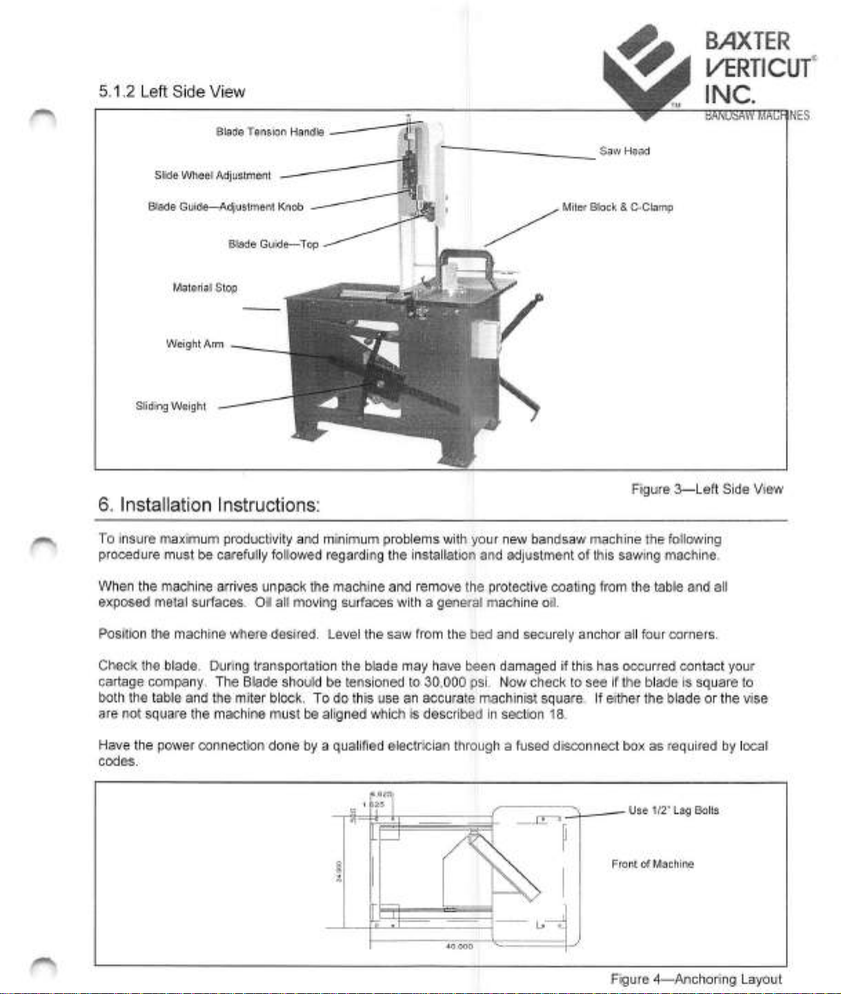
5.1.2
Left
Side
View
B>iXTER
U^RTICUr
INC.
Blade
Tension
Handle
Slide
Wheel
Adjustment
Blade
Guide—Adjustment
Knob
Blade
Guide—^Top
Saw
Head
Miter
Block
&
C-Clamp
Material
Stop
Weight
Arm
Sliding
Weight
6.
Installation
Instructions:
Figure
3—Left
Side
View
To
insure
maximum
productivity
and
minimum
problems
with
your
new
bandsaw
machine
the
following
procedure
must
be
carefully
followed
regarding
the
installation
and
adjustment
of
this
sawing
machine.
When
the
machine
arrives
unpack
the
machine
and
remove
the
protective
coating
from
the
table
and
all
exposed
metal
surfaces.
Oil
all
moving
surfaces
with
a
general
machine
oil.
Position
the
machine
where
desired.
Level
the
saw
from
the
bed
and
securely
anchor
all
four
corners.
Check
the
blade.
During
transportation
the
blade
may
have
been
damaged
if
this
has
occurred
contact
your
cartage
company.
The
Blade
should
be
tensioned
to
30,000
psi.
Now
check
to
see
if
the
blade
is
square
to
both
the
table
and
the
miter
block.
To
do
this
use
an
accurate
machinist
square.
If
either
the
blade
or
the
vise
are
not
square
the
machine
must
be
aligned
which
is
described
in
section
18.
Have
the
power
connection
done
by
a
qualified
electrician
through
a
fused
disconnect
box
as
required
by
local
codes.
Use
1/2
Lag
Bolts
Front
of
Machine
Figure
4—Anchoring
Layout
27
Kenhar
Drive,
Toronto,
Ontario
Canada
M9L
1M9
tel
(416)741-7100
fax
(416)
741-7114
email
February
12,
2016
S#
6429
TO
6433
inclusive
Page
1150-5
7.
Operating
Instructions:
7.1
Electric
Control
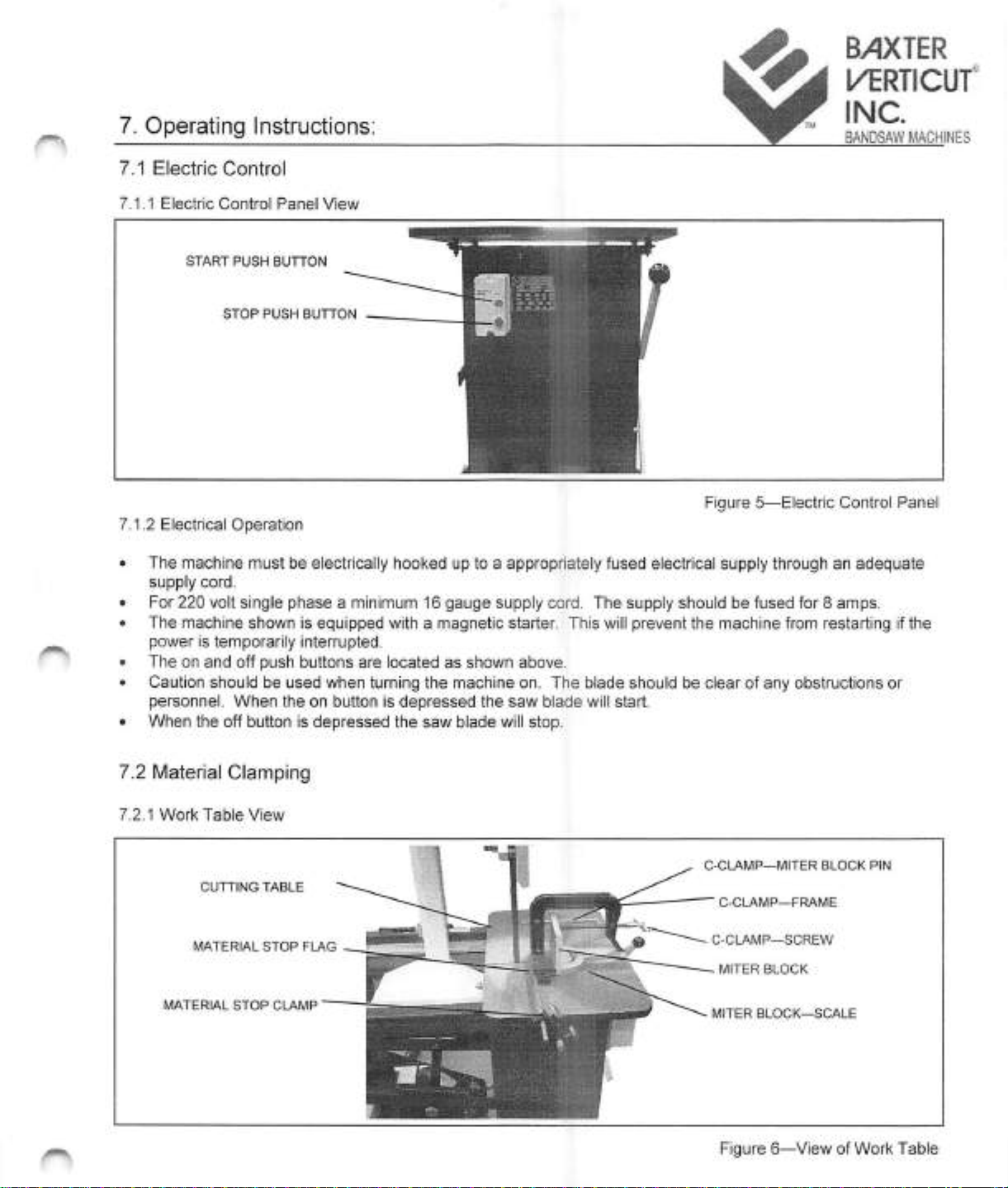
7.1.1
Electric
Control
Panel
View
START
PUSH
BUTTON
STOP
PUSH
BUTTON
BAXTER
l/^RTICUr
INC.
BANOSAW
MACHINES
Figure
5—Electric
Control
Panel
7.1.2
Electrical
Operation
•
The
machine
must
be
electrically
hooked
up
to
a
appropriately
fused
electrical
supply
through
an
adequate
supply
cord.
•
For
220
volt
single
phase
a
minimum
16
gauge
supply
cord.
The
supply
should
be
fused
for
8
amps.
•
The
machine
shown
is
equipped
with
a
magnetic
starter.
This
will
prevent
the
machine
from
restarting
if
the
power
is
temporarily
interrupted,
•
The
on
and
off
push
buttons
are
located
as
shown
above.
•
Caution
should
be
used
when
turning
the
machine
on.
The
blade
should
be
clear
of
any
obstructions
or
personnel.
When
the
on
button
is
depressed
the
saw
blade
will
start.
•
When
the
off
button
is
depressed
the
saw
blade
will
stop.
7.2
Material
Clamping
7.2.1
Work
Table
View
CUTTINGTABLE
MATERIAL
STOP
FLAG
MATERIAL
STOP
CLAMP
C-CLAMP—MITER
BLOCK
PIN
C-C
LAMP—FRAME
C-CLAMP—SCREW
MITER
BLOCK
MITER
BLOCK—SCALE
Figure
6—View
of
Work
Table
27
Kenhar
Drive,
Toronto,
Ontario
Canada
I\/I9L
1M9
tel
(416)741-7100
fax
(416)
741-7114
email
February
12.
2016
S#
6429
TO
6433
inclusive
Page
1150-6
B/IXTER
WA
l/ERTICUr
7.2.2
Miter
Block
INC.
BANDSAW
MACHINES
•
The
miter
block
is
used
to
brace
the
material
to
be
clamped.
•
The
miter
block
can
be
set
at
0°
or
between
±45°
for
miter
cutting.
•
The
scale
is
on
the
miter
block
and
the
zero
is
punched
onto
the
work
table.
•
The
miter
block
is
held
in
place
with
a
dowel
pin
and
a
bolt.
A
9/16"
wrench
is
required
to
loosen
the
bolt.
7.2.3
C-Clamp
•
The
c-clamp
is
used
to
hold
clamp
the
material
against
the
work
vise.
•
The
c-clamp
can
be
located
on
either
side
of
the
saw
blade
and
is
located
by
pushing
the
pin
through
the
miter
block.
•
The
c-clamp
can
clamp
material
up
to
4"
in
diameter.
7.2.4
Material
Stop
•
The
material
clamp
is
used
to
do
repetitive
cutting.
•
The
distance
is
set
by
clamping
the
material
flag
to
the
desired
distance.
•
The
material
clamp
assembly
is
held
in
a
block
under
table.
7.3
Saw
Carriage
Movement
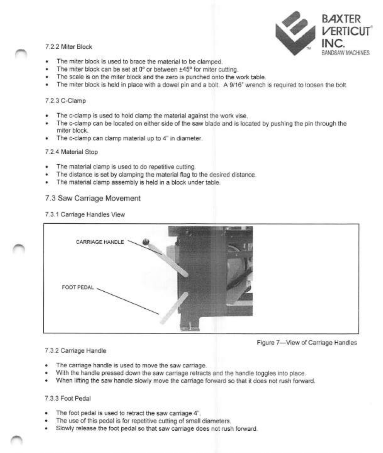
7.3.1
Carnage
Handles
View
CARRIAGE
HANDLE
Figure
7—View
of
Carriage
Handles
7.3.2
Carriage
Handle
•
The
carriage
handle
is
used
to
move
the
saw
carriage.
•
With
the
handle
pressed
down
the
saw
carriage
retracts
and
the
handle
toggles
into
place.
•
When
lifting
the
saw
handle
slowly
move
the
carriage
forward
so
that
it
does
not
rush
forward.
7.3.3
Foot
Pedal
•
The
foot
pedal
Is
used
to
retract
the
saw
carriage
A".
•
The
use
of
this
pedal
is
for
repetitive
cutting
of
small
diameters.
•
Slowly
release
the
foot
pedal
so
that
saw
carriage
does
not
rush
forward.
27
Kenhar
Drive,
Toronto,
Ontario
Canada
M9L
1M9
tel
(416)741-7100
fax
(416)
741-7114
email
February
12,
2016
S#
6429
TO
6433
inclusive
Page
115C-7

^
BAXTER
WA
l^RTICUr
7.4
Saw
Operation
INC.
^
8ANDSAW
MACHINES
•
Clamp
material
firmly
making
certain
that
the
material
is
level
and
square
with
the
machine.
•
To
assure
good
blade
life,
use
a
blade
that
has
at
least
three
teeth
in
contact
with
the
material
at
all
times.
•
Start
the
saw.
•
Advance
the
saw
blade
do
not
release
the
handle
until
the
cut
has
begun.
Lack
of
care
at
this
point
could
result
in
loss
of
blade
alignment.
•
The
counter
weight
on
the
left
side
of
the
machine
will
adjust
the
cutting
pressure
to
suit
the
thickness
of
material
and
the
blade
size.
•
When
the
saw
cut
is
finished
press
the
stop
button
to
turn
the
machine
off.
7.5
Cutting
Force
7.5.1
Adjusting
Cutting
Force
View
7.5.2
Cutting
Pressure
Adjustment
Figure
8—Hydraulic
Control
Panel
View
The
cutting
pressure
is
adjusted
by
positioning
the
weight
on
the
weight
cross
arm.
Position
the
weight
to
the
front
on
the
machine
for
a
greater
cutting
pressure,
while
towards
the
back
decreases
the
cutting
pressure.
Low
cutting
pressure
is
used
for
soft
materials
such
as
aluminum,
while
higher
pressure
are
used
for
tool,
and
machinery
steels
and
materials
which
work
harden.
7.6
Saw
Travel
Adjustment
7.6.1
Travel
Adjustment
Limit
Setting
View
SAW
CARRIAGE
AUTOMATIC
STOP
LIMIT
SWITCH
(optional)
CARRIAGE
STOP
DEPTH
OF
CUT
SCALE
Figure
9—Travel
Limit
Switches
View
27
Kenhar
Drive,
Toronto,
Ontario
Canada
IVI9L
11VI9
tel
(416)741-7100
fax
(416)
741-7114
email
info(gverticut.com
February
12,
2016
S#
6429
TO
6433
inclusive
Page
115C-8
B/IXTER
I/ERTICUf
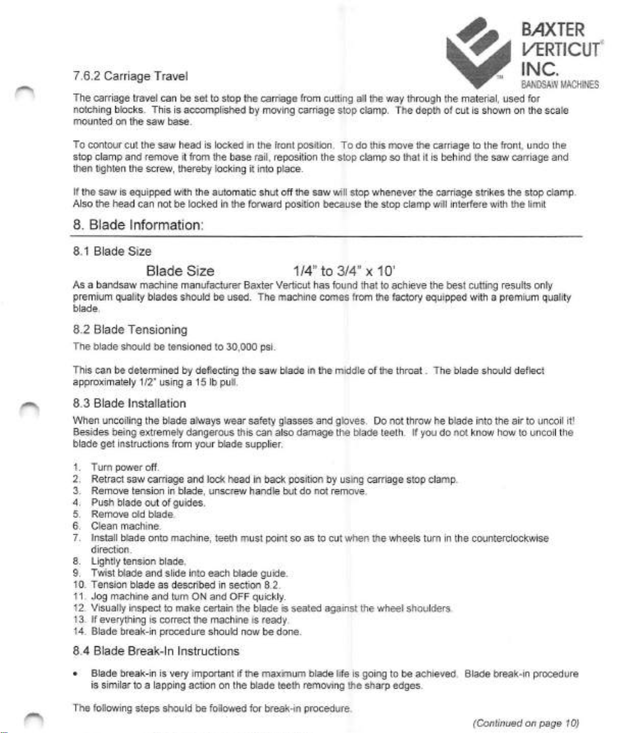
7.6.2
Carriage
Travel
INC.
^
BANOSAW
MACHINES
The
carriage
travel
can
be
set
to
stop
the
carriage
from
cutting
all
the
way
through
the
material,
used
for
notching
blocks.
This
is
accomplished
by
moving
carriage
stop
clamp.
The
depth
of
cut
is
shown
on
the
scale
mounted
on
the
saw
base.
To
contour
cut
the
saw
head
is
locked
In
the
front
position.
To
do
this
move
the
carriage
to
the
front,
undo
the
stop
clamp
and
remove
it
from
the
base
rail,
reposition
the
stop
clamp
so
that
It
Is
behind
the
saw
carriage
and
then
tighten
the
screw,
thereby
locking
it
Into
place.
If
the
saw
Is
equipped
with
the
automatic
shut
off
the
saw
will
stop
whenever
the
carriage
strikes
the
stop
clamp.
Also
the
head
can
not
be
locked
in
the
forward
position
because
the
stop
clamp
will
Interfere
with
the
limit
8.
Blade
Information:
8.1
Blade
Size
Blade
Size
1/4"
to
3/4"
x
10'
As
a
bandsaw
machine
manufacturer
Baxter
Vertlcut
has
found
that
to
achieve
the
best
cutting
results
only
premium
quality
blades
should
be
used.
The
machine
comes
from
the
factory
equipped
with
a
premium
quality
blade.
8.2
Blade
Tensioning
The
blade
should
be
tensioned
to
30,000
psi.
This
can
be
determined
by
deflecting
the
saw
blade
In
the
middle
of
the
throat.
The
blade
should
deflect
approximately
1/2"
using
a
15
lb
pull.
8.3
Blade
Installation
When
uncoiling
the
blade
always
wear
safety
glasses
and
gloves.
Do
not
throw
he
blade
into
the
air
to
uncoil
it!
Besides
being
extremely
dangerous
this
can
also
damage
the
blade
teeth.
If
you
do
not
know
how
to
uncoil
the
blade
get
instructions
from
your
blade
supplier.
1.
Turn
power
off.
2.
Retract
saw
carriage
and
lock
head
In
back
position
by
using
carriage
stop
clamp.
3.
Remove
tension
in
blade,
unscrew
handle
but
do
not
remove.
4.
Push
blade
out
of
guides.
5.
Remove
old
blade.
6.
Clean
machine.
7.
Install
blade
onto
machine,
teeth
must
point
so
as
to
cut
when
the
wheels
turn
in
the
counterclockwise
direction.
8.
Lightly
tension
blade.
9.
Twist
blade
and
slide
into
each
blade
guide.
10.
Tension
blade
as
described
in
section
8.2.
11.
Jog
machine
and
turn
ON
and
OFF
quickly.
12.
Visually
inspect
to
make
certain
the
blade
is
seated
against
the
wheel
shoulders.
13.
If
everything
Is
correct
the
machine
Is
ready.
14.
Blade
break-In
procedure
should
now
be
done.
8.4
Blade
Break-In
Instructions
•
Blade
break-in
is
very
important
if
the
maximum
blade
life
is
going
to
be
achieved.
Blade
break-In
procedure
is
similar
to
a
lapping
action
on
the
blade
teeth
removing
the
sharp
edges.
The
following
steps
should
be
followed
for
break-in
procedure.
(Continued
on
page
10)
27
Kenhar
Drive,
Toronto,
Ontario
Canada
M9L
1M9
tel
(416)741-7100
fax
(416)
741-7114
email
February
12,
2016
S#
6429
TO
6433
Inclusive
Page
115C-9

BAXTER
1/ERTiCUf
(Continued
from
page
9)
BAN
1.
Select the
proper
cutting
speed
for
the
material
to
be
cut.
2.
Cut
a
25%
of
the
normal
cutting
pressure
setting
for
10
minutes
3.
Increase
cutting
pressure
to
50%
of
normal
setting
and
cut
for
10
minutes
4.
Increase
cutting
pressure
to
75%
of
normal
setting
and
cut
for
10
minutes.
5.
Increase
cutting
pressure
to
100%
of
normal
and
proceed
to
cut.
Check
with
you
blade
supplier
for
specific
instructions.
The
blade
equipped
on
the
machine
from
the
factory
has
already
been
broken-in
for
your
convenience.
9.
Cutting
Speed:
9.1
Machine
Speeds
Machine
Speeds
mSS
75.
130,
215,
350
ft/min
^
GEARBOX
PULLEY
23,
40,
65,
107
m/min
V-BELT
3VX-335
OTOR
PULLEY
BELT
TENSION
SETTING
SCREW
9.2
Adjusting
Blade
Speed
Figure
10—Drive
Pulleys
1.
Turn
machine
off
and
lock
out.
2.
Move
carriage
forward.
3.
Lift
up
motor
and
move
belt
to
desired
speed.
Belt
must
be
on
pulley
steps
which
are
in
line
with
each
other.
4.
Lower
motor.
5.
Machine
is
ready.
9.3
Blade
Speed
Chart
(for
bimetal
blades)
MATERIAL
CARBON
STEEL—LOW
&
MEDIUM
130—215
CARBON
STEEL—HIGH
75—130
STRUCTURAL
STEEL
130—215
FREE
CUTTING
MATERIAL
215
DIE
STEEL
75
TOOL
STEEL
75
HOT
WORK
STEEL
75—130
STAINLESS
STEEL
75
CAST
IRON
130
ALUMINUM
350
SPEED
(FEET
PER
MINUTE)
27
Kenhar
Drive,
Toronto.
Ontario
Canada
M9L
1M9
tel
(416)741-7100
fax
(416)
741-7114
email
February
12,
2016
S#6429
TO
6433
inclusive
Page
115C-10

10.
Cutting
Trouble-Shooting
Guide:
B>1XTER
l/ERTiCUf
INC.
BANDSAW
MACHINES
PROBLEM
excessive
blade
breakage
not
cutting
square
blade
twisting
teeth
stripping
PROBABLE
CAUSE
teeth
too
coarse
misalignment
of
guides
excessive
tension
blade
speed
too
fast
excessive
feed
vise
not
square
material
not
square
excessive
pressure
improper
blade
tension
blade
dull
excessive
blade
pressure
blade
jamming
in
cut
SOLUTION
use
finer
pitch
adjust
blade
guides
adjust
blade
tension
lower
speed
reduce
feed
square
vise
clamp
material
correctly
reduce
feed
pressure
adjust
tension
change
blade
adjust
feed
pressure
decrease
feed
pressure
blade
not
in
alignment
with
guide
check
guide
for
wear
and
adjust
material
not
clamped
securely
in
vise
gullets
filling
13
teeth
not
in
contact
with
'
material
^
excessive
feed
clamp
material
firmly
use
coarser
pitch
use
finer
pitch
reduce
feed
early
tooth
wear
excessive
speed
blade
too
coarse
feed
too
low
j
decrease
speed
'
use
finer
pitch
increase
feed
blade
will
not
cut
blade
teeth
pointing
in
the
wrong
remove
blade,
turn
blade
inside
direction
out,
teeth
must
point
in
direction
of
travel
motor
fails
to
develop
full
power,
low
voltage
overload
power
line
overload
under
size
wire
air
circulation
to
motor
is
restricted
correct
supply
voltage
reduce
load
on
line
trips
increase
wire
size
and
or
diameter
clean
air
vents
in
motor
27
Kenhar
Drive,
Toronto.
Ontario
Canada
M9L
1M9
tel
(416)741-7100
fax
(416)
741-7114
email
February
12,
2016
S#
6429
TO
6433
inclusive
Page
1150-11
B>1XTER
L^RTICUf
INC.
11
Warrantv
BANDSAW
MACHINES
The
machine
is
warranted
to
be
free
from
failure
resulting
from
defective
material
and
workmanship
under
proper
use
and
service
for
a
period
of
one
year,
single
shift
use,
from
the
date
of
shipment
to
the
end
user.
Baxter
Verticut's
sole
obligation
under
this
warranty
is
limited
to
repair
or
replacement
without
charge
of
any
part
which
our
inspection
discloses
to
be
defective,
all
work
is
done
at
Baxter
Verticut's
factory.
A
return
goods
authorization
number
must
be
first
obtained
and
return
freight
must
be
prepaid.
The
warranty
does
not
cover
maintenance
and
wear
items,
including
but
not
limited
to;,
saw
blade,
belts,
filters,
oil,
etc.
Electric
motor,
pumps,
electric
components,
hydraulic
components,
hoses
and
any
other
items
used
in
the
construction
of
the
machine,
but
not
made
by
Baxter
Verticut
are
subject
to
the
warranty
of
the
original
equipment
makers
warranty.
Liability
and
or
obligation
by
Baxter
Verticut
for
damages,
whether
general,
special
or
for
negligence
and
expressly
including
any
incidental
and
consequential
damages
is
herby
disclaimed.
Baxter
Verticut's
sole
obligation
to
repair
or
replace
shall
be
the
limit
of
its
liability
under
this
warranty.
Baxter
Verticut
Inc.
is
not
responsible
for
any
consequential
damage
resulting
from
the
failure
of
our
machine,
regardless
of
the
cause.
This
is
the
only
warranty
which
applies.
12.
Lubrication:
ITEM
LUBRICANT
QUANTITY
FREQUENCY
Gearbox
Argon
EP1
1
Kilogram
Yearly
General
Oil
ESSO
Febis
K68
As
required
Dally
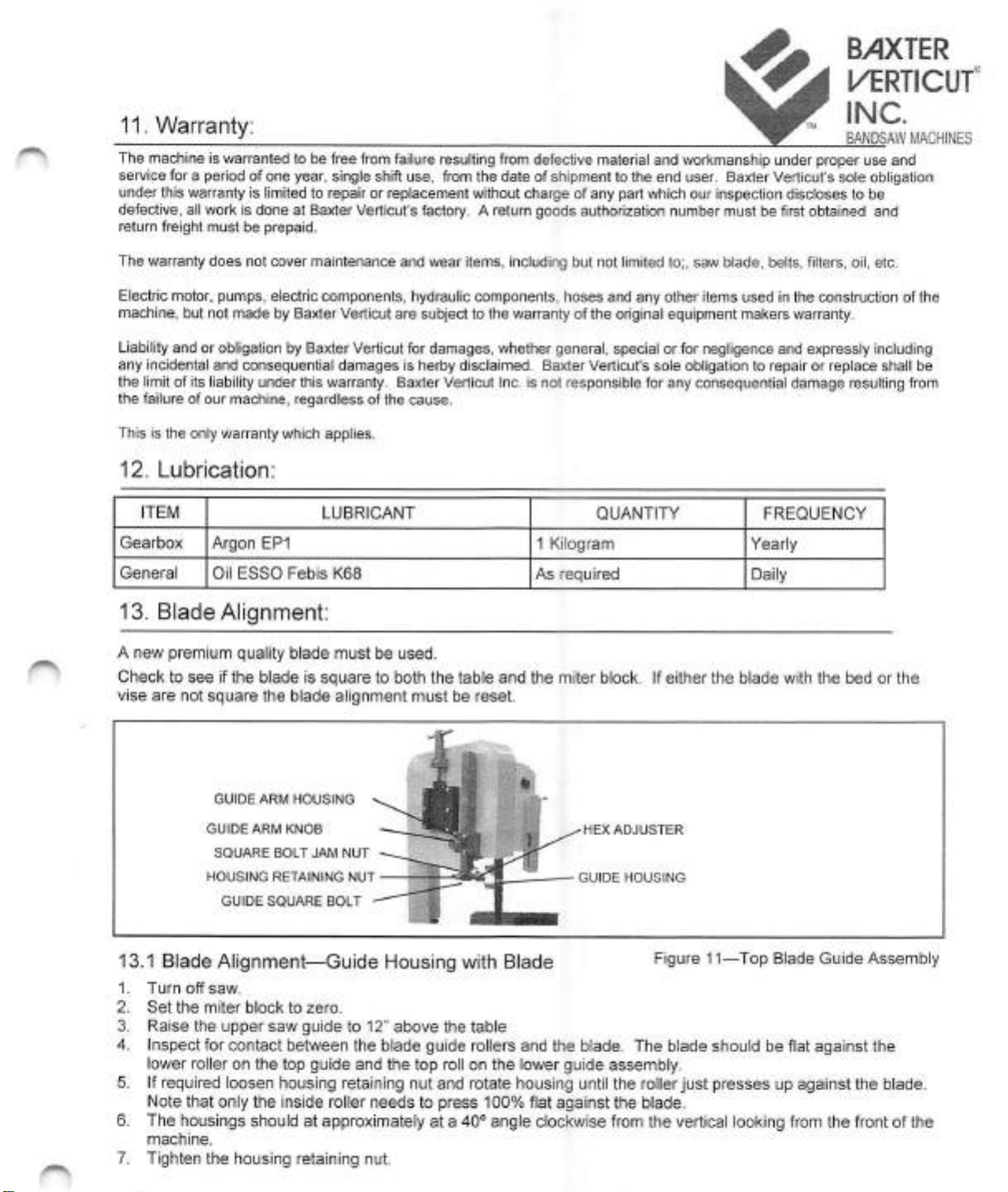
13.
Blade
Alignment:
A
new
premium
quality
blade
must
be
used.
Check
to
see
If
the
blade
Is
square
to
both
the
table
and
the
miter
block.
If
either
the
blade
with
the
bed
or
the
vise
are
not
square
the
blade
alignment
must
be
reset.
HEX
ADJUSTER
GUIDE
HOUSING
GUIDE
ARM
HOUSING
GUIDE
ARM
KNOB
SQUARE
BOLT
JAM
NUT
HOUSING
RETAINING
NUT
GUIDE
SQUARE
BOLT
13.1
Blade
Alignment—Guide
Housing
with
Blade
Figure
11—Top
Blade
Guide
Assembly
1.
Turn
off
saw.
2.
Set
the
miter
block
to
zero.
3.
Raise
the
upper
saw
guide
to
12"
above
the
table
4.
Inspect
for
contact
between
the
blade
guide
rollers
and
the
blade.
The
blade
should
be
flat
against
the
lower
roller
on
the
top
guide
and
the
top
roll
on
the
lower
guide
assembly.
5.
If
required
loosen
housing
retaining
nut
and
rotate
housing
until
the
roller
just
presses
up
against
the
blade.
Note
that
only
the
inside
roller
needs
to
press
100%
flat
against
the
blade.
6.
The
housings
should
at
approximately
at
a
40°
angle
clockwise
from
the
vertical
looking
from
the
front
of
the
machine.
7.
Tighten
the
housing
retaining
nut.
27
Kenhar
Drive,
Toronto,
Ontario
Canada
M9L
1M9
tel
(416)741-7100
fax
(416)
741-7114
email
February
12,
2016
S#
6429
TO
6433
Inclusive
Page
1150-12
B/IXTER
l/ERTICUf
13.2
Blade
Alignment—Blade
with
Table
INC.
BANDSAW
MACHINES
1.
Turn
off
saw.
2.
Set
the
miter
block
to
zero.
3.
Move
the
saw
carriage
to
the
forward
position.
4.
Raise
the
upper
saw
guide
to
12"
above
the
table
5.
Check
to
see
if
the
blade
Is
square
to
the
table.
6.
If
not
square
release
the
square
bolt
jam
nut
and
rotate
the
guide
square
bolt
until
the
blade
is
square
to
the
table.
7.
Tighten
jam
nut.
13.3
Blade
Alignment—Blade
with
Miter
Block
1.
Turn
off
saw.
2.
Set
the
miter
block
to
zero.
3.
Move
the
saw
carriage
to
the
forward
position.
4.
Raise
the
upper
saw
guide
to
12"
above
the
table
5.
Check
to
see
if
blade
is
square
to
the
miter
block.
6.
Readjust
miter
block
to
make
square.
7.
Hold
square
on
miter
block
and
against
blade.
Retract
carriage
and
see
if
movement
is
parallel
to
square.
8.
If
still
not
square
start
over
as
described
in
section
13.1
and
13.2.
9.
If
problems
still
exist
contact
the
factory
for
further
assistance.
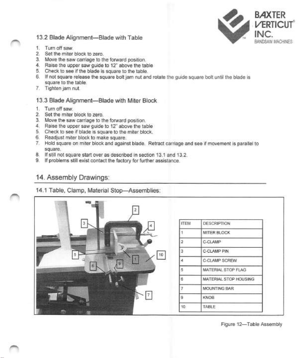
14.
Assembly
Drawings:
14.1
Table,
Clamp.
Material
Stop—^Assemblies;
DESCRPTON
MITER
BLOCK
C-CLAMP
C-CLAMP
PIN
C-CLAMP
SCREW
MATERIAL
STOP
FLAG
MATERIAL
STOP
HOUSING
MOUNTING
BAR
Figure
12—Table
Assembly
27
Kenhar
Drive,
Toronto,
Ontario
Canada
M9L
1M9
tel
(416)741-7100
fax
(416)
741-7114
email
February
12,
2016
S#6429
TO
6433
inclusive
Page
1150-13

14.2
Blade
Guide
Assembly
14.3
Slide
Assembly:
TM
BAXTER
L/ERTICUr
INC.
BANDSAW
MACHINES
QTY
DESCRIPTION
BLADE
GUIDE
ROLLER
BLADE
GUIDE
HOUSING
HEX
ADJUSTING
BOLT
SWING
BOLT
GUIDE
ARM
BAR
BEARING
1011562
ARM
HOUSING
HOUSING
BASE
GUIDE
ARM
KNOB
LOWER
TEE
BLOCK
SWING
ARM
JAM
NUT
HOUSING
LOCKING
NUT
WASHER
Figure
13—Blade
Guide
Assembly
DESCRIPTION
WHEEL—SLIDE
WASHER
BEARING
6011526
RETAINING
RING
BEAR
NG
SPACER
SLIDE
PLATE
SL
DERAILS
HANDLE
BODY
HANDLE
BLOCK
RUBBER
BAND
Figure
14—Slide
Assembly
27
Kenhar
Drive,
Toronto,
Ontario
Canada
M9L
1M9
tel
(416)741-7100
fax
(416)
741-7114
email
February
12,
2016
S#
6429
TO
6433
Inclusive
Page
1150-14
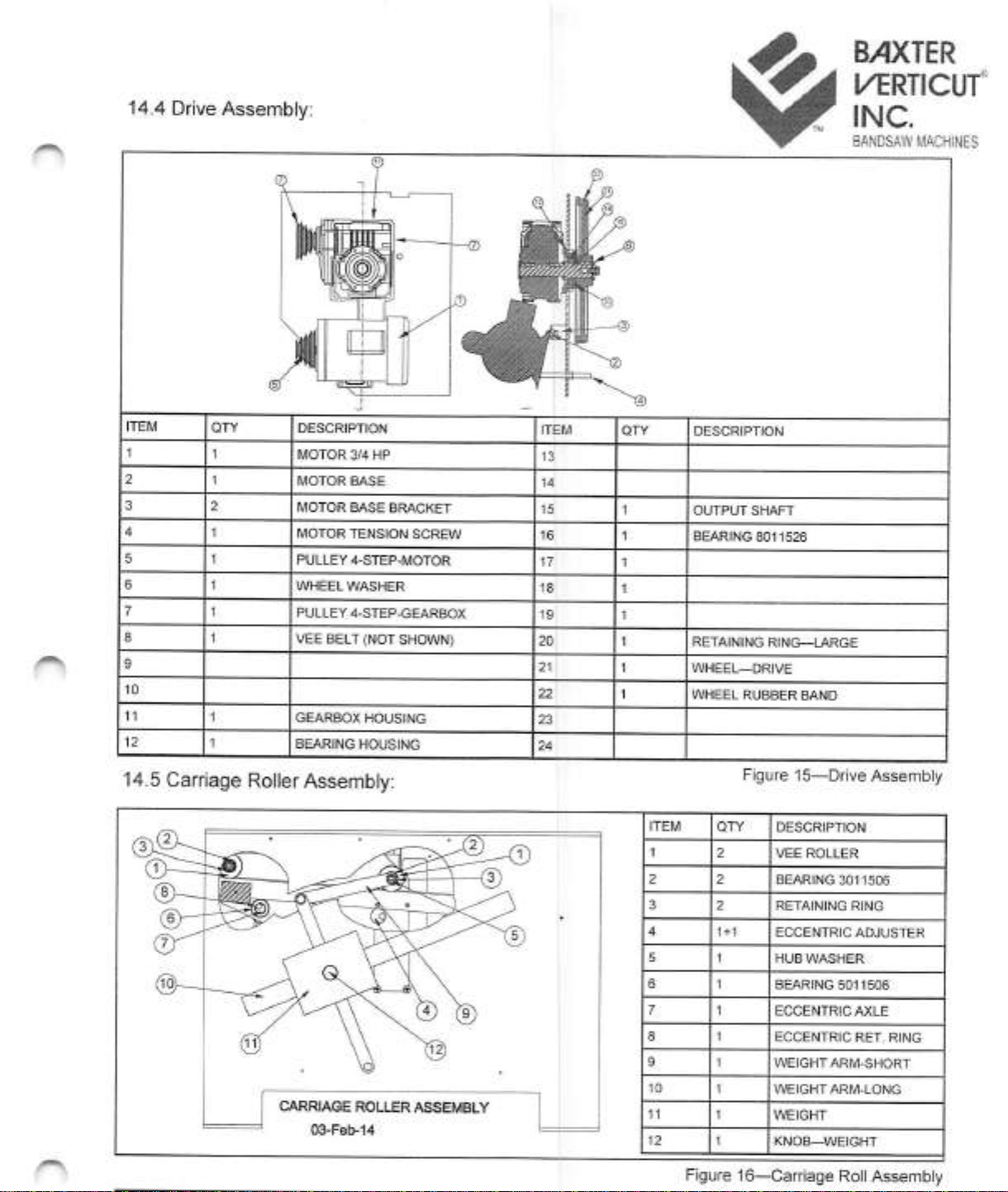
14.4
Drive
Assembly:
BAXTER
U^RTICUf
INC.
BANDSAW
MACHINES
DESCRIPTION
DESCRIPTON
MOTOR
3/4
HP
MOTOR
BASE
MOTOR
BASE
BRACKET
OUTPUT
SHAFT
MOTOR
TENSION
SCREW
BEARING
8011526
PULLEY
4-STEP-MOTOR
WHEEL
WASHER
PULLEY
4-STEP-GEARBOX
VEE
BELT
(NOT
SHOWN)
RETAINING
RING—LARGE
WHEEL—DRIVE
WHEEL
RUBBER
BAND
GEARBOX
HOUSING
BEARING
HOUSING
Figure
15—Drive
Assembly
14.5
Carriage
Roller
Assembly:
DESCRIPTION
VEE
ROLLER
BEARING
3011506
RETAINING
RING
ECCENTRIC
ADJUSTER
HUB
WASHER
BEARING
5011506
ECCENTRIC
AXLE
ECCENTRIC
RET,
RING
WEIGHT
ARM-SHORT
WEIGHT
ARM-LONG
CARRIAGE
ROLLER
ASSEMBLY
WEIGHT
03-Feb-14
KNOB—WEIGHT
Figure
16—Carriage
Roll
Assembly
27
Kenhar
Drive,
Toronto,
Ontario
Canada
M9L
1M9
tel
{416)741-7100
fax
(416)
741-7114
email
info(@verticut,com
February
12,
2016
S#
6429
TO
6433
inclusive
Page
115C-15

B>IXTER
ZwA
l/ERTICI
l/ERTICU
14.6
Electric
Schematic-Single
Phase-115/1/60
T
INC.
BANDSAW
MACHINES
OPTIONAL
MACHINE
SERIAL
NUMBEf
IPAGE
1
OF
1
1
FILE
DIR.:
C:\DC\MISC\ELEC^
6403
TO
6415
INCLUSIVE
1
DWG.NO.
115C-S#64D3TO
6415INCL-151105-12H
27
Kenhar
Drive,
Toronto.
Ontario
Canada
M9L
1I\/19
tel
(416)741-7100
fax
(416)
741-7114
email
February
12,
2016
S#
6429
TO
6433
inclusive
Page
1150-16
Table of contents
Popular Saw manuals by other brands


DeWalt
DeWalt DWS5100 manual

TYROLIT Hydrostress
TYROLIT Hydrostress FSD1274 Series operating instructions

Wen
Wen CT1274 instruction manual

Mafell
Mafell MS 55 / 36 V Original operating instructions

Bosch
Bosch 1671K - Litheon 36V 6 1/2? Circular Saw parts list

Feider Machines
Feider Machines FSOR20V-U instruction manual