Bayer HealthCare SeedGrowth CBT Series Operating manual

CBT UNITIZED
MAINTENANCE GUIDE

2GENERAL INFORMATION
This manual contains technical information regarding Bayer SeedGrowth™ Equipment.
Please read and understand these instructions completely before proceeding to install and
operate the equipment. Bayer CropScience reserves the right to change specications,
models, components, or materials at any time without notice. For additional equipment
information contact us at 1.800.634.6738. Please have this manual available when contacting
Bayer CropScience.
Always use caution and common sense
when working with any chemical. Read the
product label and SDS carefully and follow
their instructions exactly as described.
Optimal operating conditions for this
piece of equipment requires an ambient
temperature 32° F to +104° F (0° C to
+40° C), relative humidity less than 90%
(minimum condensation). Make necessary
provisions to protect this piece of equipment
against excessive dust, particles containing
iron, moisture and against corrosive and
explosive gases.
Our technical information is based on
extensive testing and is, to the best of our
current knowledge, true and accurate but
given without warranty as the conditions
of use and storage are beyond our control.
Variables, such as humidity, temperature,
change in seed size or variety and viscosity
of chemical products can all affect the
accuracy of the chemical application and
seed coverage. To ensure the desired application rate and optimum seed coverage, check
the calibration periodically throughout the day, and make adjustments as needed.
Bayer CropScience LP
1451 Dean Lakes Trail
Shakopee, Minnesota 55379
USA
Bayer SeedGrowthTM and the Bayer Cross are registered trademarks of Bayer.
BCSCBTUNITIZEDMAINTENANCEGUIDE09142015
Phone: +1 952 445 6868
Toll Free: +1 855 363 3152
E-mail: equipment@bayer.com
Web: www.seedgrowth.bayer.com
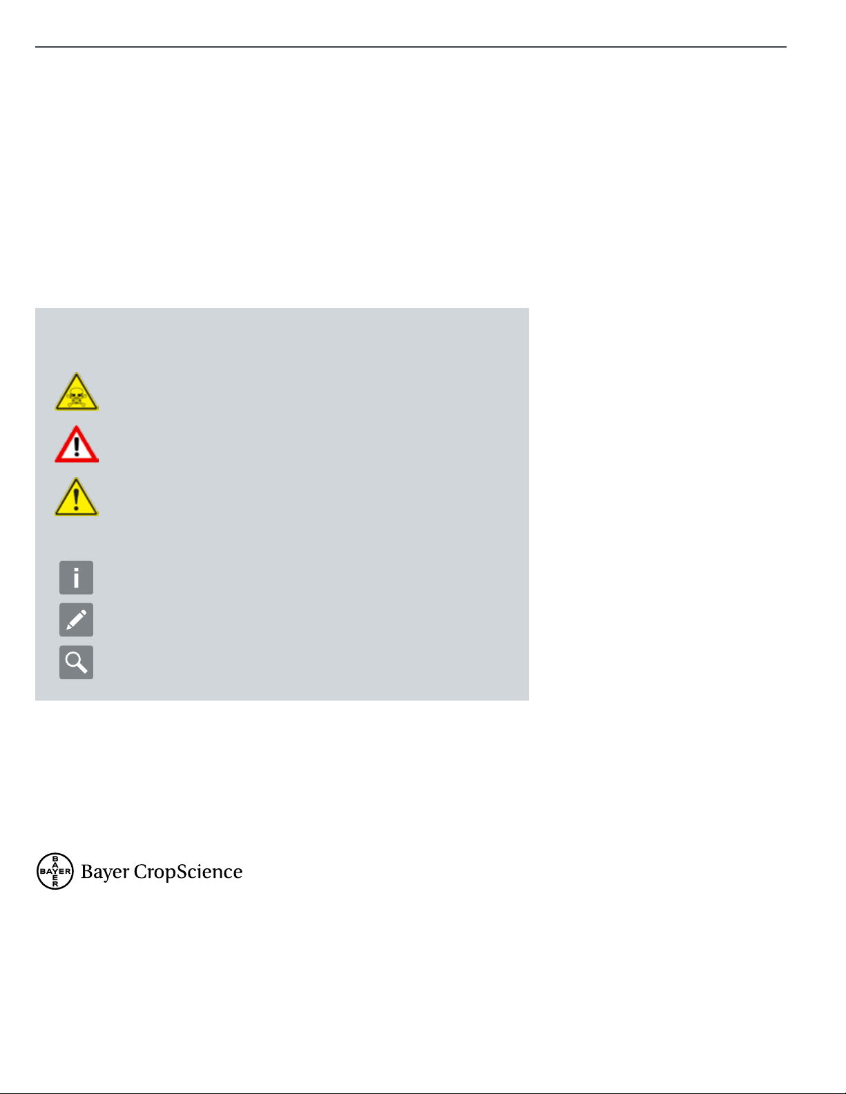
This manual uses signal words and symbols to help avoid personal injury. Danger,
Warning, and Caution are signal words used to identify the level of hazard.
Danger alerts that an extreme hazard will cause serious injury or death if
operators or installers do not follow the recommended precautions.
Warning alerts that a hazard may cause serious injury or death if
operators or installers do not follow the recommended precautions.
Caution alerts that a hazard may cause minor or moderate injury if
operators or installers do not follow the recommended precautions.
Tip: calls attention to special information.
Note: emphasizes general information worthy of attention.
Example: gives a problem or exercise that illustrates a method
or principle.

CONTENT
#1 SYSTEM DIAGRAM 04
#2 SURGE HOPPER 05
#3 WEIGH SCALE 06
#4 POWDER FEEDER 08
#5 DUST COLLECTOR 10
#6 MIXING BOWL 12
#7 CONTROL PANEL 16
#8 RECOMMENDED SPARE PARTS 17
#9 LP300 TANK 18
#10 EXPOSURE CONTROL 23
#11 STEWARDSHIP AT BAYER 24
#12 REFERENCE SYMBOLS 25
3
CONTENTS

4SYSTEM DIAGRAM
EXPLANATORY NOTES
PREVENTIVE MAINTENANCE
Suggestions made in this manual are recommended for the longevity of the machine. Failure to perform general maintenance
may hinder the overall performance of the machine and possibly void any warranty expressed or implied.
SYSTEM DIAGRAM
CBT200 UNITIZED VOLUMETRIC SYSTEM, REF.
HI/LO Sensors
Viewing Windows
Weigh Scale
Dust Evac Port
Mixing Bowl
Seed Discharge
Bowl Frame
Seed Inlet
Dust Evac Port
Surge Hopper
Mounted Control
Panel
Dust Evac Assy
Filter Bag
Closed Calibration
LP 300 Litre Tank

Step 2: Use a vacuum to clean build-up from inside the hose and
the dust evacuation port opening. When nished cleaning, replace
the hose on the dust evacuation port and tighten in place with a slot
screwdriver.
SURGE HOPPER
Dust Evacuation Port
Step 1: Use a slot screwdriver to loosen and remove the hose from
the dust evacuation port.
HI/LO Sensor Kit
Step 1: Check the signal cables for wear.
Disconnect signal cables from control panel.
Use a nut driver to remove/replace the HI/LO
sensor kit, if needed.
Step 2: Replace the HI/LO sensor kit and
tighten in place with a nut driver. Connect
signal cables to the control panel.
Warning!
Exercise extreme caution when working
with dust and chemicals! Refer to the Exposure
Control Guide at the end of the manual, page 21. Wear
proper personal protective equipment: goggles, a face
respirator, chemical resistant gloves and coveralls.
Required maintenance tools
• Screwdriver (slot)
• Nut driver
• 7/16”, ½” and 10mm socket heads
• Vacuum
• Putty knife
5
SURGE HOPPER

WEIGH SCALE
Step 2: Use a vacuum and putty knife to clean seed, dust and chaff
from inside the weigh hopper.
Quarter turn key
Scale & Frame Assembly
Step 1: Use the quarter turn key to remove the guard panels (4) from
the scale & frame sub-assembly.
Remove scale guards
Scale without guards
6WEIGH SCALE

7
WEIGH SCALE
Step 3: Replace scale guard panels. Use the quarter turn key to lock
each guard panel latch. The guard panel with the dust evacuation port
needs to face out towards the front of the bowl & frame (CBT200 only),
as shown below.
Dust evacuation port orientation, CBT200 only, ref.
PM CHECKLIST
CBT Treater PM Checklist
1: Clean seed weigh-hopper area of dust/chaff - Weekly
Required maintenance tools
• Screwdriver (slot)
• Nut driver
• 7/16”, ½” and 10mm socket heads
• Vacuum
• Putty knife

POWDER FEEDER
Step 1: At the end of each treating session or whenever the operator
needs to change powder product, run all of the powder out of
the powder hopper. Since powder absorbs ambient air moisture
and solidies if left over time, cleaning helps prevent “caking up”.
Release the powder tube assembly clamps to remove it from the
powder feeder and the mixing bowl cover. Clean thoroughly.
Step 2: Use 1/2” wrench to remove the four nuts that hold the auger
tube and gasket onto the backside of the powder base. Slide the
auger tube and gasket from the powder body. Clean thoroughly.
Step 3: Always use a vacuum (not compressed air) to safely clean
the machine.
Connected to
Bowl Cover
Connected to
Auger Tube
See assembled
images Step 6
on page 9.
8POWDER FEEDER

9
POWDER FEEDER
Step 4: Thoroughly clean the auger assembly
and the powder body interior of dry product.
Step 5: Open the hopper lid and clean the
interior of dry product.
Step 6: When ready to use, replace the auger tube and gasket. Tighten
hardware securely. Connect the powder tube assembly to the auger
tube and the mixing bowl cover.
Note: for complete gear motor service instructions, refer to
manufacturer’s manual shipped with the powder feeder.
PM CHECKLIST
Powder Feeder PM Checklist
1: Clean powder feeder - Weekly
CBT25, 50 & 100
CBT200 only
CBT25, 50 & 100
CBT200 only

DUST COLLECTOR
Dust Collector Hoses
Step1: Use a slot screwdriver to remove and replace hoses.
Note: for complete dust collector service instructions,
refer to manufacturer’s manuals shipped with the CBT.
Filter Bag
Step 1: Disconnect the Filter Bag and dispose
of contents according to local regulations.
DO NOT DISCARD CONTENTS IN THE
TRASH! Replace the Bag with a new one
when needed. Connect the Filter Bag onto
the Dust Collector.
10 DUST COLLECTOR

11
DUST COLLECTOR
PM CHECKLIST
Dust Collector PM Checklist
1: Clean the dust collector - Weekly

MIXING BOWL
Bowl Access Panels
Step 1: Use a 10mm socket head to remove four (4) 6mm bolts, washers & lock washers. Remove both (R-L) bowl access panel doors from the
lower body wrap. Use a vacuum to clean seed and dust from underneath the mixing bowl. Check door gaskets for wear, replace if needed. Replace
both access panel doors on the lower body wrap.
Step 2: Always use a vacuum
(not compressed air) to
safely clean the machine.
12 MIXING BOWL

13
MIXING BOWL
Filter Regulator
Step 1: Check the water level and drain quarterly.
Note: For complete drive shaft or bowl replacement instructions,
email us at equipment@bayer.com for those specic manuals.
For complete bowl & blower motor service instructions, refer to
manufacturer’s manuals shipped with the CBT.
Step 2: Check the V-belt for wear and replace if needed. Check the
bowl gear motor for leaks and oil level.
Bowl Motor V-Belt
Step 1: Use the quarter turn key (inset photo) to unlock and remove all
panel doors from the bowl support frame.
Step 3: Loosen the tensioner and slip the V-belt off the sheaves.
Replace the V-belt on both sheaves. Tighten the tensioner.
New style - check oil level Check V-belt

14 MIXING BOWL
Bowl Cover
Step 1: Loosen and remove (4) wing nuts on
chemical inlet plate. Remove plate from cover.
Step 2: Loosen and remove the seed inlet
collar from the bottom of the transition.Step 5: Hook each scale clamp into the bowl
cover. Lift both clamps up to lift up the bowl
cover.
Step 6: Carefully move the swing arm and
bowl cover away from the mixing bowl.
Step 3: Disconnect each hold down clamp
on the bowl cover.
Step 4: Push each tab in to lower both scale
clamps.
Remove lid cleanout panel BRemove lid cleanout panel A Remove chemical inlet plate
For CBT25,
50 & 100 see
pictures above.
Remove wing
nuts. Remove
3-piece Plates.
CBT200 bowl cover only

15
MIXING BOWL
PM CHECKLIST
CBT Bowl & Frame PM Checklist
1: Check/drain lter/regulator - Quarterly
2: Clean area under bowl - Weekly
3: Inspect atomizer belt - Weekly
4: Inspect bowl gearbox for oil leaks - Weekly
5: Inspect bowl gearbox oil level - Quarterly
6: Replace bowl gearbox oil - 25,000 hrs
7: Clean bowl / wrap gap - Weekly
8: Clean inside of bowl /wrap / lid - per Shift
9: Inspect air lter for under bowl blower - Monthly
Blower Filter
Use the quarter turn key to unlock and remove the left panel door from
the bowl support frame. Loosen and remove the wing nut holding
the lter housing. Check the lter element and replace if needed
(P000544). Replace the lter housing and tighten the wing nut in
place.
Atomizer
Use 7/16 socket head to remove the ¼ bolt, washer and lock washer
that connects the atomizer to the drive shaft. Remove the atomizer
and clean residual chemical. Wipe down the bowl and inside the
bowl cover. Replace the atomizer on the drive shaft and securely
tighten in place.
Move the bowl cover / Swing arm over the mixing bowl and latch each
hold down clamp securely. Replace the chemical inlet plate on the
mixing bowl cover. Tighten the four (4) wing nuts on the chemical inlet
plate.

Control Panel
Periodically remove, inspect and clean out
air lters. Grasp the top of the lter frame and
pull away from the panel, as shown below.
Remove the lter and clean with a vacuum
cleaner or replace the lter. Repeat for the air
lter on the other top side of the Controller.
Main Control Panel
At the end of the treating season, ensure the Power Lever is in the
OFF position, as shown.
CONTROL PANEL
16 CONTROL PANEL

17
RECOMMENDED SPARE PARTS
RECOMMENDED
SPARE PARTS
CBT25
PARTS KIT: CBT SCALE HOPPER - 79971451
PARTS KIT: CBT25 & 50 DRIVE/ BOWL - 79999186
CBT50
PARTS KIT: CBT SCALE HOPPER - 79971451
PARTS KIT: CBT25 & 50 DRIVE/ BOWL - 79999186
CBT100
PARTS KIT: CBT SCALE HOPPER - 79971451
PARTS KIT: CBT100 DRIVE & BOWL - 80011253
CBT200
PARTS KIT: CBT SCALE HOPPER - 79971451
PARTS KIT: CBT200 DRIVE & BOWL - 80029829
LP300 TANK
PARTS KIT: LP300 TANK ASSY - 80217056

LP300 TANK
Agitation Coupler Inspection
Step 1: Use a 7/16” socket head to remove
two 1/4-20 bolts, washer and nuts from the
Gear Reducer Mount Guard. Remove the
Reducer Mount Guard (front panel) and check
the 3-piece Drive Shaft Coupler for wear.
Warning! The Gear Reducer has been tested and
adjusted at the factory. Dismantling or replacement
of components must be done by Bayer CropScience
or an authorized representative, in order to
maintain the warranty expressed or implied.
!
Remove
Calibration Cylinder
Step 1: Remove wing nuts (3)
from the stud on the Top End Cap.
Remove the Top End Cap.
Step 2: Remove the Graduated
Cylinder from the Lower End Cap and
completely clean any chemical residue.
Step 3: Check the Gasket in the Lower
and Upper End Caps for cracks or wear
and replace if needed. Replace the
Graduated Cylinder in the Lower End cap.
Step 4: Replace the Top End Cap on the
Graduated Cylinder. Thread and tighten
each wing nut (3) evenly on each stud.
Remove
Replace
18 LP300 TANK

19
LP300 TANK
Note: For complete Pump Service instructions, refer to
manufacturer’s manual shipped with the LP300 Tank.
PM CHECKLIST
LP300 Tank PM Checklist
1: Inspect plumbing for leakage - Weekly
2: Clean Graduated Cylinder - Quarterly
3: Rinse inside of Tank & Plumbing - End of Season
Pump Tubing
Step 1: Check all tubing and plumbing
connections weekly for leaks, cracks
or wear. Replace if needed.

20 LP300 TANK
Change IP Pump Element
Step 1: Use the Pump Handle to open the Pump Head. Remove the
old Pump Element from the Pump Head Rollers. Push in the orange
press lock tting to remove the Pump Element from both the right and
left side of the Pump Head (refer to Steps 2, 3 & 4).
Step 2: Lay the new Pump Element on the Pump Rollers. Align the
Pump Element behind the Pump Head Clips, as shown.
Step 3: Insert the new Pump Element press lock tting into the Tank
Elbow on the right hand side of the Pump Head, as shown.
Step 4: Connect the other press lock tting into the Pump Discharge
Plumbing Assembly on the left hand side of the Pump Head, as shown.
Step 5: Align the Pump Element on the Pump Head grooves (both
sides) to ensure proper t, as shown (may require two people).
Step 6: Use the Pump Handle to close the Pump Head, as shown.
This manual suits for next models
4
Table of contents
Other Bayer HealthCare Industrial Equipment manuals