Bayer HealthCare Clinitek 500 User manual

Urine Chemistry Analyzer
Operating
Manual
63032-Cover 11/8/06 9:10 AM Page 1

50241854 ii Revised 10/06
©1998, 2003 Bayer HealthCare LLC
All Rights Reserved
Printed in Ireland
SECOND EDITION
Unless otherwise noted,
all trademarks are the property
of Bayer HealthCare LLC.
Bayer Diagnostics Europe Limited
Chapel Lane, Swords, Co. Dublin, Ireland
Bayer HealthCare LLC
Subsidiary of Bayer Corporation
Tarrytown, NY 10591-5097 USA
Manufactured in the UK for Bayer
63032-Cover 11/8/06 9:10 AM Page 2

TABLE OF CONTENTS
Revised 5/01 iii
Section Page
1 INTRODUCTION
General Description and Intended Use ......................................................1.1
Components and Mechanical Operation .....................................................1.1
Optical System.............................................................................1.3
Calibration .................................................................................1.3
Specifications..............................................................................1.4
Tables of Results...........................................................................1.5
2 INSTALLATION
General Information ........................................................................2.1
Environmental Factors .....................................................................2.1
Unpacking .................................................................................2.1
Instrument Setup ..........................................................................2.2
Interfacing to a Printer .....................................................................2.5
Interfacing to a Computer ..................................................................2.6
Interfacing to a Bar Code Reader............................................................2.6
Initial Instrument Check ....................................................................2.6
3 SELECTING YOUR OPTIONS
General Information ........................................................................3.1
Setup Routine .............................................................................3.3
A. Setup Menu #1 (Date; Time; Computer port; Printer)...................................3.4
B. Password Screen.....................................................................3.5
C. Setup Menu #2 (Language; Result units; Plus system; Test) ............................3.6
D. Setup Menu #3 (Date, Time format; Date, Time separator)..............................3.7
E. Setup Menu #4 (Tests to report; Mark positives;
Positive levels; Normal levels — SG/pH, Creatinine) .................................3.7
F. Setup Menu #5 (Color; Choices for color, clarity; Use defaults) .........................3.9
G. Setup Menu #6 (Positive levels — Color, Clarity; Flags for reports) .....................3.11
H. Setup Menu #7 (Edit flagged results; Enter sample ID; Tech ID).........................3.12
I. Setup Menu #8 (Computer port options; Bar code reader; Password) ...................3.12
J. Setup Menu #9 (Reset to defaults; Perform hardware tests) ............................3.15
When Setup is Complete ...................................................................3.16
Software Flow Chart........................................................................3.17
4 INSTRUMENT OPERATION
General Information ........................................................................4.1
Getting Ready to Run ......................................................................4.1
Testing Controls ...........................................................................4.3
Testing Routine Specimens.................................................................4.4
A. Basic Operation ......................................................................4.4
B. If IDs are Used in a Loadlist...........................................................4.6
C. If IDs are Used Without a Loadlist.....................................................4.7
D. Printing/Transmitting Results .........................................................4.8
40069/Table of Contents 11/8/06 10:04 AM Page iii

iv Revised 5/03
Section Page
4 INSTRUMENT OPERATION
Continued
End-of-Run Reports........................................................................4.8
Editing Results in the Confirmatory Report................................................4.8
Recalling Results ..........................................................................4.9
Operating Notes............................................................................4.10
5 CARE OF THE INSTRUMENT
General Cleaning ...........................................................................5.1
Daily Cleaning .............................................................................5.1
Disinfection................................................................................5.3
Changing the Paper ........................................................................5.4
6 SUPPLIES & OPTIONAL EQUIPMENT .........................................................6.1
7 MINOR REPAIR
General Information ........................................................................7.1
Printer Replacement .......................................................................7.1
Calibrating the Touch Screen ...............................................................7.3
8 TROUBLESHOOTING AND SERVICE
General Information ........................................................................8.1
When to Call for Assistance ..............................................................8.1
Where to Call for Assistance .............................................................8.1
Troubleshooting Chart......................................................................8.4
Preservice Checklist........................................................................8.10
9 SUPPLIES & REPLACEMENT PARTS
Supplies/Optional Equipment ...............................................................9.1
Replacement Parts .........................................................................9.1
Appendix
CPI COMPUTER AND PRINTER INTERFACE
General Information......................................................................CPI.1
Cable and Pin Specifications — Serial Port .............................................CPI.1
Cable and Pin Specifications — Parallel Port............................................CPI.1
IND INDEX .....................................................................................IND.1
TABLE OF CONTENTS
40069/Table of Contents 11/8/06 10:04 AM Page iv

The instrument is a reflectance spectrophotometer that
analyzes the color and intensity of the light reflected from
the reagent area and reports the results in clinically mean-
ingful units (see Tables 1-1 through 1-6). No calculations
are required by the user. Calibration is performed auto-
matically each time a Reagent Strip is analyzed.
Components and Mechanical
Operation
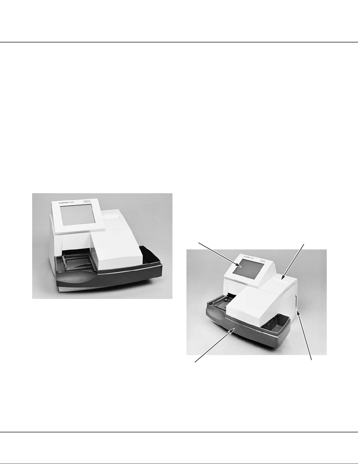
Figures 1-2 and 1-3 show the major components of the
CLINITEK®500 instrument. The program card is inserted
into the card receptacle ‹!£. The strips are transported
across the read area ‹@£, where incubation and reading of
the tests occur. All test results are printed by the internal
thermal printer ‹#£ (unless this option has been selected
as “OFF” by the operator). All communications between
the operator and the instrument are made through the
interactive touch display ‹$£. Response keys and dialogue
are displayed on the screen; responses are made by touch-
ing the appropriate key symbol on the screen.
Figure 1-2
Section 1
INTRODUCTION
General Description and
Intended Use
The CLINITEK®500 Urine Chemistry Analyzer (Figure
1-1) is a semiautomated, benchtop instrument designed
to “read” traditional Bayer Reagent Strips for Urinalysis
(e.g., MULTISTIX®10 SG) and Bayer MULTISTIX PRO®
family of Reagent Strips. The instrument system includes
a program card that contains the programming necessary
for the CLINITEK 500 instrument to read these Reagent
Strips. Strips can be laid on the instrument at any time (if
specimen IDs are not used); a sensor detects the strip’s
presence, which activates the strip movement and read-
ing cycle. Communication between the instrument and
the user is through the use of a touch screen and inter-
active software.
Figure 1-1
Depending on the product being used, Bayer Reagent
Strips contain reagent areas for testing glucose, bilirubin,
ketone (acetoacetic acid), specific gravity, occult blood,
pH, protein, urobilinogen, nitrite, and leukocytes. In addi-
tion to these tests, MULTISTIX PRO Reagent Strips also
contain protein–low and creatinine reagent areas. A sin-
gle protein result is reported from the two protein tests;
this reading is compared to the creatinine result to pro-
vide a protein-to-creatinine ratio. The instrument can also
determine and report the color of the urine, and the clar-
ity can be entered for each specimen.
Revised 5/01 1.1
‹$£
‹!£
‹#£
‹@£
63032-Section 1 11/8/06 9:15 AM Page 1

1.2 Revised 9/98
The fixed platform ‹%£ consists of three sections: the
strip loading station , the incubation/read station ,
Figure 1-3
Two readheads, located inside the read area, scan the
length of each Reagent Strip at a specific time in the incu-
bation cycle. The first readhead reads the reagent areas
requiring shorter incubation times; the second reads those
requiring longer incubation times. The pins continue to
move the strip along the platform until it drops into the
waste bin.
5b
5a
INTRODUCTION
Figure 1-4 shows the rear view of the CLINITEK 500
instrument. The line cord is connected into the line cord
receptacle ‹*£. The instrument is turned
on
by pressing
the power switch ‹(£ to the ON (“—”) position. The inter-
face connectors ‹)£ are the points at which a computer,
printer, and/or handheld bar code reader may be inter-
faced with the instrument. An extra port is available for
future use. The instrument is cooled by a fan ‹_£.
Figure 1-4
All programming for the instrument is contained in a
replaceable program card ‹+£, shown in Figure 1-5. The
card is programmed with such information as error
messages, operating sequence, and the wavelengths
and algorithms used to convert reflectance into clinically
meaningful results. It also contains the customized Setup
information selected by the user. The card is easily replace-
able for future software updates.
and the waste bin . A Reagent Strip is placed onto the
instrument at the strip loading station. Detection of a strip
by the strip sensor ‹^£ causes the instrument to begin
cycling. The strip is moved toward the incubation/read
station by the push bar ‹&£. The strip is then moved through
the incubation/read station by a series of pins; the pins
move the strip at a rate of about 1⁄2inch every 7 seconds.
5c
{
5c
‹^£
5a
‹&£ ‹%£
5b
‹(£‹*£‹)£
‹_£
63032-Section 1 11/8/06 9:15 AM Page 2

Revised 9/99 1.3
Figure 1-5
The instrument stores the operating parameters, plus
up to 500 patient results and 200 control results, in a
battery-backed RAM memory. This memory is saved
regardless of whether the power is
on
or
off.
The operat-
ing parameters (including those selected by the user) are
also stored on the program card and can be copied to
other CLINITEK 500 instruments.
Optical System
The instrument contains two readheads, each of which
contains an incandescent lamp and photodiode pack.
When a strip is moved into position under the readhead,
the calibration cycle is performed (see “Calibration” next),
then the readhead scans the entire length of the strip, mea-
suring the light reflectance of each reagent pad. A portion
of the light striking the pad is reflected back to the pho-
todiode pack. The light reflected at specific wavelengths
from the test pad is dependent upon the degree of color
change in the pad and is directly related to the concen-
tration of the particular constituent in the urine.
The photodiode pack contains four filters, one each at
400–510 nm (blue), 510–586 nm (green), 586–660 nm
(red), and 825–855 nm (IR). The light intensity detected
by the photodiode pack is converted into electrical im-
pulses, which are processed by the instrument’s micro-
processor and converted into clinically meaningful results.
The results can be printed by the internal printer; they can
also be sent to a computer and/or a form or 80-column
printer.
Calibration
Calibration is performed at each readhead immediately
before each Reagent Strip is read. The fixed platform
contains two white calibration bars that are positioned
directly under each readhead. As a strip comes into posi-
tion under a readhead, the instrument is calibrated for that
scanning cycle by reading the calibration bar. The Reagent
Strip is then scanned and the data stored in memory.
‹+£
63032-Section 1 11/8/06 9:15 AM Page 3

1.4 Revised 5/03
Specifications
Power Required:
100–240 VAC 10%, 50–60 Hz
Maximum Power Input:
72 VA
Fuse Rating: (not user-replaceable)
2A, 250 V, 2AG, SB(T)
*Line Leakage Current:
<0.5 milliamperes in normal condition
<3.5 milliamperes in single fault condition
Heat Output:
Approximately 246 BTU/hour
Dimensions:
Depth — 32.4 cm (12.8 in.)
Width — 37.7 cm (14.8 in.)
Height — 28.2 cm (11.1 in.)
Weight:
7.4 kg (16.3 lb.)
Ambient Operating Temperature Range:
18°C to 30°C (64°F to 86°F)
Ambient Operating Humidity Range:
20% to 80% relative humidity
Optimum Operating Conditions:
22°C to 26°C (72°F to 79°F);
35% to 55% relative humidity
NOTE: Because of the nature of the urobilinogen and
leukocyte reagents found on Bayer Reagent Strips,
these two results may be decreased at temperatures
below 22°C (72°F) and increased at temperatures
above 26°C (79°F).
Safety Standards:
The CLINITEK®500 Urine Chemistry Analyzer (Model
6470) is listed by the Underwriters’ Laboratories ( )
and the Canadian Standards Association ( ) as cer-
tified and complies with the safety standards specified
in UL 3101 and CSA-C22.2, No. 1010.1. The instru-
ment meets the provisions of the IVD Directive 98/79/EC
(Oct./1998) ( ), which includes the EMC Directive
89/336 Amendment 92/31/EEC and the Low Voltage
Safety Directive 73/23/EEC.
The safety standards specify that the instrument must
operate safely in the following conditions:
• indoor use only
• installation category II (IEC 1010)
• pollution degree 2 (IEC 1010)
• maximum altitude 2000 meters (6560 feet)
Warning:
The instrument is for professional,
in vitro
diagnostic
use ( ) and must be used in the manner specified
in the Operating Manual in order to provide the safety
and performance standards specified.
Symbols on Back of Analyzer:
Centronics Port
(Parallel) for Printer
Serial Port (RJ45)
for Bar Code Reader
Not a telephone jack
Serial Port (RJ45)—
not currently active
Serial Port (EIA-232D)
for host computer
Serial Number
ASTM Software Interface:
Conforms to ASTM E 1381-91, “Specification for Low-
Level Protocol to Transfer Messages between clinical
laboratory instrument and computer systems” and
ASTM E 1394-91, “Specification for Transferring
Information Between Clinical Instruments and Computer
Systems.”
INTRODUCTION
*Testing protocol and allowable limits as specified by the safety
standards for laboratory equipment outlined in UL 3101-1, CSA 22.2
No. 1010.1, and IEC 1010-1.
63032-Section 1 11/8/06 9:15 AM Page 4

Revised 5/01 1.5
Table 1-1
Traditional Bayer Reagent Strips
ENGLISH — CONV.
Units — Conventional
*Color may be preceded with “LT.” or “DK.” when determined by the instrument. If determined visually, Shaded areas = default abnormal results
*default descriptions can be changed by the user; “OTHER” can also be reported.
†Reported results are default descriptions that can be changed by the user.
TABLES OF RESULTS
(determined visually)
Reported Results
Test Abbreviation Units
Normal System Plus System
NEGATIVE 500 NEGATIVE 2
Glucose GLU mg/dL 100 >=1000 TRACE 3
250 1
Bilirubin BIL NEGATIVE MODERATE NEGATIVE 2
SMALL LARGE 13
NEGATIVE 40 NEGATIVE 2
Ketone KET mg/dL TRACE >=80 TRACE 3
15 1
<=1.005 1.020
Specific Gravity SG 1.010 1.025 No Difference
1.015 >=1.030
NEGATIVE SMALL NEGATIVE 1
Occult Blood BLO TRACE-LYSED MODERATE TRACE-LYSED 2
TRACE-INTACT LARGE TRACE-INTACT 3
5.0 6.5 8.0
pH pH 5.5 7.0 8.5 No Difference
6.0 7.5 >=9.0
NEGATIVE 100 NEGATIVE 2
Protein PRO mg/dL TRACE >=300 TRACE 3
30 1
0.2 4.0
Urobilinogen URO E.U./dL 1.0 >=8.0 No Difference
2.0
Nitrite NIT NEGATIVE POSITIVE No Difference
NEGATIVE MODERATE NEGATIVE 2
Leukocytes LEU TRACE LARGE TRACE 3
SMALL 1
YELLOW GREEN
Color*COL ORANGE BLUE No Difference
RED BROWN
CLEAR TURBID
Clarity†CLA SL CLOUDY OTHER No Difference
CLOUDY
Traditional Bayer Reagent Strips
63032-Section 1 11/8/06 9:15 AM Page 5

1.6 Revised 5/01
INTRODUCTION
Reported Results
Test Abbreviation Units
Normal System Plus System
NEGATIVE 3NEGATIVE 2
Glucose GLU 14TRACE 3
21
Bilirubin BIL NEGATIVE 2No Difference
13
NEGATIVE 3NEGATIVE 2
Ketone KET 14TRACE 3
21
<=1.005 1.020
Specific Gravity SG 1.010 1.025 No Difference
1.015 >=1.030
NEGATIVE 1
Occult Blood BLD 2No Difference
3
5.0 6.5 8.0
pH pH 5.5 7.0 8.5 No Difference
6.0 7.5 >=9.0
NEGATIVE 2NEGATIVE 2
Protein PRO 3TRACE 3
11
3.2 66
Urobilinogen UBG umol/L 16 >=131 No Difference
33
Nitrite NIT NEGATIVE POSITIVE No Difference
NEGATIVE 3NEGATIVE 2
Leukocytes LEU 14TRACE 3
21
YELLOW GREEN
Color*COL ORANGE BLUE No Difference
RED BROWN
CLEAR TURBID
Clarity†CLA SL CLOUDY OTHER No Difference
CLOUDY
Table 1-2
Traditional Bayer Reagent Strips
ENGLISH — NORDIC
Units — Nordic Plus System
*Color may be preceded with “LT.” or “DK.” when determined by the instrument. If determined visually, Shaded areas = default abnormal results
*default descriptions can be changed by the user; “OTHER” can also be reported.
†Reported results are default descriptions that can be changed by the user.
(determined visually)
Reported Results
Test Abbreviation Units
Normal System Plus System
NEGATIVE 3NEGATIVE 2
Glucose GLU 14TRACE 3
21
Bilirubin BIL NEGATIVE 2No Difference
13
NEGATIVE 3NEGATIVE 2
Ketone KET 14TRACE 3
21
<=1.005 1.020
Specific Gravity SG 1.010 1.025 No Difference
1.015 >=1.030
NEGATIVE 1
Occult Blood BLD 2No Difference
INTACT 3
5.0 6.5 8.0
pH pH 5.5 7.0 8.5 No Difference
6.0 7.5 >=9.0
NEGATIVE 2NEGATIVE 2
Protein PRO 3TRACE 3
11
3.2 66
Urobilinogen UBG umol/L 16 >=131 No Difference
33
Nitrite NIT NEGATIVE POSITIVE No Difference
NEGATIVE 3NEGATIVE 2
Leukocytes LEU 14TRACE 3
21
YELLOW GREEN
Color*COL ORANGE BLUE No Difference
RED BROWN
CLEAR TURBID
Clarity†CLA SL CLOUDY OTHER No Difference
CLOUDY
Table 1-2
Traditional Bayer Reagent Strips
ENGLISH — NORDIC
Units — Nordic Plus System
*Color may be preceded with “LT.” or “DK.” when determined by the instrument. If determined visually, Shaded areas = default abnormal results
*default descriptions can be changed by the user; “OTHER” can also be reported.
†Reported results are default descriptions that can be changed by the user.
Traditional Bayer Reagent Strips
63032-Section 1 11/8/06 9:15 AM Page 6

Revised 5/01 1.7
(determined visually)
Table 1-3
Traditional Bayer Reagent Strips
ENGLISH — S.I.
Units — International (S.I.)
*Color may be preceded with “LT.” or “DK.” when determined by the instrument. If determined visually, Shaded areas = default abnormal results
*default descriptions can be changed by the user; “OTHER” can also be reported.
†Reported results are default descriptions that can be changed by the user.
Reported Results
Test Abbreviation Units
Normal System Plus System
NEGATIVE 28 NEGATIVE 2
Glucose GLU mmol/L 5.5 >=55 TRACE 3
14 1
Bilirubin BIL NEGATIVE MODERATE NEGATIVE 2
SMALL LARGE 13
NEGATIVE 3.9 NEGATIVE 2
Ketone KET mmol/L TRACE >=7.8 TRACE 3
1.5 1
<=1.005 1.020
Specific Gravity SG 1.010 1.025 No Difference
1.015 >=1.030
NEGATIVE Ca 25 NEGATIVE 1
Occult Blood BLD Ery/uL TRACE-LYSED Ca 80 TRACE-LYSED 2
TRACE-INTACT Ca 200 TRACE-INTACT 3
5.0 6.5 8.0
pH pH 5.5 7.0 8.5 No Difference
6.0 7.5 >=9.0
NEGATIVE 1.0 NEGATIVE 2
Protein PRO g/L TRACE >=3.0 TRACE 3
0.3 1
3.2 66
Urobilinogen UBG umol/L 16 >=131 No Difference
33
Nitrite NIT NEGATIVE POSITIVE No Difference
NEGATIVE Ca 125 NEGATIVE 2
Leukocytes LEU Leu/uL Ca 15 Ca 500 TRACE 3
Ca 70 1
YELLOW GREEN
Color*COL ORANGE BLUE No Difference
RED BROWN
CLEAR TURBID
Clarity†CLA SL CLOUDY OTHER No Difference
CLOUDY
Traditional Bayer Reagent Strips
63032-Section 1 11/8/06 9:15 AM Page 7

1.8 Revised 5/01
Printed/Displayed Results
Test Abbreviation Units Normal System +/– System
NEGATIVE 500 NEGATIVE 2
Glucose GLU mg/dL 100 >=1000 TRACE 3
250 1
Bilirubin BIL NEGATIVE MODERATE NEGATIVE 2
SMALL LARGE 13
NEGATIVE 40 NEGATIVE 2
Ketone KET mg/dL TRACE >=80 TRACE 3
15 1
<=1.005 1.020
Specific Gravity SG 1.010 1.025 No Difference
1.015 >=1.030
NEGATIVE SMALL NEGATIVE 1
Occult Blood BLO TRACE-LYSED MODERATE TRACE-LYSED 2
TRACE-INTACT LARGE TRACE-INTACT 3
5.0 6.5 8.0
pH pH 5.5 7.0 8.5 No Difference
6.0 7.5 >=9.0
0.2 4.0
Urobilinogen URO E.U./dL 1.0 >=8.0 No Difference
2.0
Nitrite NIT NEGATIVE POSITIVE No Difference
NEGATIVE MODERATE NEGATIVE 2
Leukocytes LEU TRACE LARGE TRACE 3
SMALL 1
NEGATIVE 100 NEGATIVE 2
Protein PRO mg/dL 15 300 LOW 3
30 1
10 200
Creatinine CRE mg/dL 50 300 No Difference
100
NORMAL DILUTE†
Protein-to- NORMAL
Creatinine P:C mg/g 150 ABNORMAL No Difference
Ratio 300 ABNORMAL
>500 ABNORMAL
YELLOW GREEN
Color* COL ORANGE BLUE No Difference
RED BROWN
CLEAR TURBID
Clarity** CLA SL CLOUDY OTHER No Difference
CLOUDY
Table 1-4
MULTISTIX PRO Reagent Strips
ENGLISH — CONV.
Units — Conventional
† Specimen is too dilute to accurately determine ratio result. Repeat test on new specimen. Shaded areas = default abnormal results
*Color may be preceded with “LT.” or “DK.” when determined by the instrument. If determined visually,
default descriptions can be changed by the user; “OTHER” can also be reported.
**Reported results are default descriptions that can be changed by the user.
(determined visually)
MULTISTIX PRO Reagent Strips
INTRODUCTION
63032-Section 1 11/8/06 9:15 AM Page 8

Revised 10/06 1.9
MULTISTIX PRO Reagent Strips
Printed/Displayed Results
Test Abbreviation Units Normal System +/– System
NEGATIVE 3NEGATIVE 2
Glucose GLU 14TRACE 3
21
Bilirubin BIL NEGATIVE 2
13No Difference
NEGATIVE 3NEGATIVE 2
Ketone KET 14TRACE 3
21
<=1.005 1.020
Specific Gravity SG 1.010 1.025 No Difference
1.015 >=1.030
NEGATIVE 1
Occult Blood BLD 2No Difference
INTACT 3
5.0 6.5 8.0
pH pH 5.5 7.0 8.5 No Difference
6.0 7.5 >=9.0
3.2 66
Urobilinogen UBG umol/L 16 >=131 No Difference
33
Nitrite NIT NEGATIVE POSITIVE No Difference
NEGATIVE 3NEGATIVE 2
Leukocytes LEU 14TRACE 3
21
NEGATIVE 2
Protein PRO LOW 3No Difference
1
0.9 17.7
Creatinine CRE mmol/L 4.4 26.5 No Difference
8.8
NORMAL DILUTE†
Protein-to- NORMAL
Creatinine P:C mg/mmol 17.0 ABNORMAL No Difference
Ratio 33.9 ABNORMAL
>56.6 ABNORMAL
YELLOW GREEN
Color* COL ORANGE BLUE No Difference
RED BROWN
CLEAR TURBID
Clarity** CLA SL CLOUDY OTHER No Difference
CLOUDY
Table 1-5
MULTISTIX PRO Reagent Strips
ENGLISH — NORDIC
Units — Nordic Plus System
†Specimen is too dilute to accurately determine ratio result. Repeat test on new specimen. Shaded areas = default abnormal results
**Color may be preceded with “LT.” or “DK.” when determined by the instrument. If determined visually,
default descriptions can be changed by the user; “OTHER” can also be reported.
**Reported results are default descriptions that can be changed by the user.
(determined visually)
63032-Section 1 11/8/06 9:15 AM Page 9

1.10 Revised 5/01
INTRODUCTION
Printed/Displayed Results
Test Abbreviation Units Normal System +/– System
NEGATIVE 28 NEGATIVE 2
Glucose GLU mmol/L 5.5 >=55 TRACE 3
14 1
Bilirubin BIL NEGATIVE MODERATE NEGATIVE 2
SMALL LARGE 13
NEGATIVE 3.9 NEGATIVE 2
Ketone KET mmol/L TRACE >=7.8 TRACE 3
1.5 1
<=1.005 1.020
Specific Gravity SG 1.010 1.025 No Difference
1.015 >=1.030
NEGATIVE Ca 25 NEGATIVE 1
Occult Blood BLD Ery/uL TRACE-LYSED Ca 80 TRACE-LYSED 2
TRACE-INTACT Ca 200 TRACE-INTACT 3
5.0 6.5 8.0
pH pH 5.5 7.0 8.5 No Difference
6.0 7.5 >=9.0
3.2 66
Urobilinogen UBG umol/L 16 >=131 No Difference
33
Nitrite NIT NEGATIVE POSITIVE No Difference
NEGATIVE Ca 125 NEGATIVE 2
Leukocytes LEU Leu/uL Ca 15 Ca 500 TRACE 3
Ca 70 1
NEGATIVE 1.0 NEGATIVE 2
Protein PRO g/L 0.15 3.0 LOW 3
0.3 1
0.9 17.7
Creatinine CRE mmol/L 4.4 26.5 No Difference
8.8
NORMAL DILUTE†
Protein-to- NORMAL
Creatinine P:C mg/mmol 17.0 ABNORMAL No Difference
Ratio 33.9 ABNORMAL
>56.6 ABNORMAL
YELLOW GREEN
Color* COL ORANGE BLUE No Difference
RED BROWN
CLEAR TURBID
Clarity** CLA SL CLOUDY OTHER No Difference
CLOUDY
Table 1-6
MULTISTIX PRO Reagent Strips
ENGLISH — S.I.
Units — International (S.I.)
†Specimen is too dilute to accurately determine ratio result. Repeat test on new specimen. Shaded areas = default abnormal results
**Color may be preceded with “LT.” or “DK.” when determined by the instrument. If determined visually,
default descriptions can be changed by the user; “OTHER” can also be reported.
**Reported results are default descriptions that can be changed by the user.
(determined visually)
MULTISTIX PRO Reagent Strips
63032-Section 1 11/8/06 9:15 AM Page 10

Section 2
INSTALLATION
General Information
This section provides detailed installation instructions
for the CLINITEK®500 Urine Chemistry Analyzer. The
installation steps must be followed correctly to ensure
proper installation, operation, and service. Read this
Operating Manual carefully before attempting to operate the
CLINITEK 500 instrument. Follow all instructions carefully.
The CLINITEK 500 is a precision instrument and must
be handled accordingly. Rough handling or dropping of
the instrument will disturb internal calibrated optics and
electronics and/or cause other damage. Always handle
the instrument with care.
Environmental Factors
As with all sensitive electronic instruments, prolonged
exposure to excessive humidity and temperature should
be avoided. Temperature should be held relatively con-
stant to obtain the highest degree of operating stability.
The ambient temperature range for operating the instru-
ment is 18°C to 30°C (64°F to 86°F); the
optimum
temperature range is 22°C to 26°C (72°F to 79°F). At
temperatures under 22°C, urobilinogen and leukocyte
results may be decreased, and at temperatures above
26°C, increased. The ambient operating humidity range
is 20% to 80% relative humidity.
Place the instrument where it will not be subjected to
extreme temperature variations. Avoid proximity to open
windows, direct sunlight, ovens, hot plates, open burn-
ers, radiators, and dry ice baths. Do not place it on the
same bench as a source of vibration, such as a centrifuge.
The CLINITEK 500 instrument should not be used in an
explosive atmosphere. The bench space should be large
enough to allow free air circulation around the instrument
(3 inches/7.6 cm on all sides).
Unpacking
1. You should have received two cartons: one carton
contains the CLINITEK®500 instrument and a box of
accessory parts; the other (the “Installation Pack”)
contains the power cord and operating manual that
are appropriate for your country. Carefully remove the
contents of each carton. Inspect the shipping cartons,
accessory box, and instrument for visible signs of
damage. If damage to the instrument exists, immedi-
ately file a complaint with the carrier.
2. The following items, shown in Figure 2-1, are packed
with the instrument:
2. ‹!£ Fixed platform, holddown plate, and waste bin liner
2. ‹@£ Moving table (2)
2. ‹#£ Printer paper
2. ‹$£ Push bar (2)
2. ‹%£ Program card
2. ‹^£ Holddown plate (extra)
Figure 2-1
2.
Revised 9/99 2.1
‹&£ ‹*£
‹@£‹#£‹%£‹^£ ‹$£
‹!£
63032-Section 2 11/8/06 2:37 PM Page 1

2.2 Revised 9/99
2. The remaining items shown in Figure 2-1 are packed
in the Installation Pack and shipped in a separate con-
tainer from the instrument:
2. ‹&£ Operating manual: Binder and manual pages
(Manual pages may be supplied separately by your Bayer rep-
resentative. Depending on the language of the operating
manual you have received, there may also be a Warranty
Registration Card and/or a Customer Information Card.)
2. ‹*£ Power cord
2. Make sure all these items have been included with
your instrument, and keep them for future use.
3. After the instrument has been unpacked, place it on a
firm, level work surface in the designated work area.
The instrument should
appear
level, both side to side
and front to back. The back and sides of the instru-
ment should be at least 3 inches from an adjacent wall
or instrument.
3. NOTE: Retain the CLINITEK 500 shipping carton and
packing for at least several weeks. If the instrument
ever needs to be shipped, the shipping carton will
afford the best protection against damage.
4. Locate the piece of foam packing that is under the read
area cover. Gently pull down and forward on the foam
to remove it (Figure 2-2).
4. IMPORTANT: Be sure to remove the foam before
continuing!
Figure 2-2
5. If you have not already done so, insert the pages of
your Operating Manual into the binder.
Instrument Setup
1. Ensure that the instrument power switch is in the OFF
(“●●”) position. Then plug the instrument line cord
into the instrument and into an appropriate ground-
ed AC electrical outlet.
2. Locate the bar-coded serial number, which is found
inside the instrument near the front left corner (Figure
2-3). Write the installation date and serial number in
the spaces provided in the “Preservice Checklist” in
Section 8 and on the Manufacturer’s Warranty Page
that is found at the end of this manual (contact your
Bayer representative for your warranty information if
this page is not included in your manual).
Figure 2-3
3. If a Warranty Registration Card is found at the front
of your manual, write the installation date and instru-
ment serial number on this card. After the instrument
has been successfully installed, completely fill out the
Warranty Registration Card and mail.
INSTALLATION
63032-Section 2 11/8/06 2:37 PM Page 2

Revised 9/99 2.3
4. Install the moving table as follows:
4. a. Hold the table with the small rectangular tab fac-
ing to the back.
4. b. Align the two grooves on the bottom of the table
with the edges of the platform on which the table
rests (Figure 2-4).
Figure 2-4
2. c. Gently push the table in as far as it will go. It must
be pushed past a detent in order to be correctly in
position.
5. Next, install the fixed platform. (The holddown should
already be securely installed onto the platform. If it is
not installed, or is loose, refer to Section 5, “Daily
Cleaning,” Step 11-a, for directions on installing the
holddown.) Align the two grooves on the bottom of
the platform with the arms extending from the instru-
ment, as shown in Figure 2-5. (The ledges on the left
and right sides of the holddown align just outside the
read area cover, and the top edge of the platform aligns
just under the cover.) Gently push the platform in as
far as it will go. (It must be pushed past a slight detent
to be correctly positioned.)
5.
CAUTION: If the platform does not push in at least
halfway with only very gentle pressure, do not force
it! Ensure that the moving table is correctly positioned
and attempt to reinstall the platform.
5. NOTE: With the initial installation, you may need to
use firm pressure to push the platform the final
1⁄2inch (1.3 cm). If the platform is not fully seated, or
if it is slightly crooked, the strips may jam as they are
pushed along the platform.
Figure 2-5
6. Hold the push bar by its indented end and, with this
end slightly upward, insert the peg on the other end
of the bar into the hole in the pusher mechanism
(Figure 2-6). Lower the push bar into place.
63032-Section 2 11/8/06 2:37 PM Page 3

Figure 2-6
7. Hold the program card with the label facing forward
and the arrows pointing in and up. Insert the card into
the card receptacle (Figure 2-7) and press it in firmly
until the button above the receptacle is pushed out.
When properly inserted, the edge of the card will be
flush with the side of the instrument.
Figure 2-7
2.4 Revised 9/99
INSTALLATION
8. Install a roll of printer paper and re-install the printer
cover as follows:
a. Notice the large tab on the back side of the instru-
ment that secures the cover in place (Figure 2-8).
Press in firmly on the bottom edge of the tab and
lift the cover off.
Figure 2-8
8. b. Obtain a new roll of paper; unroll several inches and
trim the end into a long “V”. Hold the roll just above
the printer, with the paper unrolling from under-
neath. Feed the end of the paper under the roller,
then rotate the paper advance wheel in a clockwise
direction (toward the back) until several inches of
paper are exposed above the printer (Figure 2-9).
63032-Section 2 11/8/06 2:37 PM Page 4

Figure 2-9
8. c. Set the paper into position behind the printer. Then,
place the front tabs of the cover into their slots and
feed the end of the paper through the opening in
the cover. Snap the cover into place.
9. If not already installed, place a liner into the waste bin
(Figure 2-10).
Figure 2-10
Revised 5/01 2.5
Interfacing to a Printer
The CLINITEK 500 can be interfaced to most 80-
column, continuous feed printers or to the CLINITEK®
Form Printer via the printer (parallel) port that is found
on the rear of the instrument.
1. Some printers may include an interface cable that is
appropriate for use; if not, you will need to obtain the
cable separately. Refer to Appendix CPI, “COMPUT-
ER AND PRINTER INTERFACE,” for the pin specifica-
tions for the male connector. The other end of the
cable will be dependent upon the particular printer.
Appropriate cables are available at most retail com-
puter stores.
2. Connect the appropriate end of the interface cable to
the printer port on the CLINITEK 500 (labeled “ ”)
(see ‹!£ Figure 2-11 for location); connect the other
end to the printer.
Figure 2-11
‹!£ ‹#£ ‹@£
63032-Section 2 11/8/06 2:37 PM Page 5

2.6 Revised 5/03
INSTALLATION
3. Carefully read the operating manual that accompanies
the printer and become familiar with its operation
before using.
Interfacing to a Computer
The CLINITEK 500 can also be interfaced to a host
computer or LIS (Laboratory Information System) via the
serial port and a Null modem cable. The cable require-
ments for interfacing to a computer are found in Appendix
CPI, “COMPUTER AND PRINTER INTERFACE.” Connect
the appropriate end of the interface cable to the port on
the CLINITEK 500 labeled “ ” ( ‹@£ in Figure 2-11);
connect the other end to the appropriate port on the
computer, following the instructions given with the
computer.
Interfacing to a Bar Code Reader
A Handheld Bar Code Reader (Product No. 6469) is
available for use with the CLINITEK 500 Analyzer. It is
connected through the RJ45 interface port (labeled “ ”)
(‹#£ in Figure 2-11). Refer to Appendix BCR that is includ-
ed with the Handheld Reader for complete information.
Initial Instrument Check
After the CLINITEK 500 has been properly installed,
perform the following initial instrument check. The actions
that should occur during instrument operation are
described in this check. If problems occur during this
procedure or if an error message is displayed, refer to
Section 8, TROUBLESHOOTING AND SERVICE.
1. Press the power switch to the ON (“—”) position. The
push bar will move and the display will be illuminat-
ed, first showing the instrument name and a series of
dots while the system initializes. It then changes to
the title screen, which shows the software version
numbers, along with the instrument name and copy-
right information. The system then does several inter-
nal checks and procedures. Each check and its status
is displayed while the testing is being performed. Verify
that the fan is
on
by holding your hand near the fan
cover located at the upper left corner on the rear of
the instrument.
1. NOTE: If an error occurs, a message will be displayed
that instructs you either to turn the power
off,
then
back
on
after several seconds, or to contact customer
service (see Section 8, TROUBLESHOOTING AND
SERVICE).
2. The display changes to the Ready/Run screen, which
is the starting point for testing and selecting the
options that will customize the instrument to meet
your laboratory’s needs. The screen also shows the
name of the Bayer Reagent Strip for Urinalysis that is
programmed for use on the instrument (for example,
“MULTISTIX 10 SG”).
2. The Ready/Run screen will be displayed as, for
example:
Use MULTISTIX 10 SG.
Place strip.
ID:
SEQ #: 00001
Color-(not reported)
Clarity-(not reported)
Menu Tech ID:
09-05-98 10:32 AM
63032-Section 2 11/8/06 2:37 PM Page 6
Other manuals for Clinitek 500
1
Table of contents
Other Bayer HealthCare Measuring Instrument manuals
Popular Measuring Instrument manuals by other brands

Omega
Omega Vortex FV100 Series user guide

Apera
Apera 2401-C user manual

IFM Electronic
IFM Electronic ecomot200 FR-2 operating instructions

Kobold
Kobold ZUB-MANS-KON1/2 operating instructions

Emerson
Emerson Daniel 3812 Maintenance and troubleshooting manual

EINHELL
EINHELL TC-LL 2 Original operating instructions