BAYKON BX11 User manual
BX11
Smart Process Indicator
User Manual


BX11 Smart Process Indicator, User Manual, Rev. 1.8, May 2017
Pa e
1
of
48
S
AFETY
I
NSTRUCTIONS
CAUTION! READ THIS MANUAL BEFORE OPERATING OR SERVICING THIS EQUIPMENT.
FOLLOW THESE INSTRUCTIONS CAREFULLY. SAVE THIS MANUAL FOR FUTURE
REFERENCE. DO NOT ALLOW UNTRAINED PERSONNEL TO OPERATE, CLEAN, INSPECT,
MAINTAIN, SERVICE, OR TAMPER WITH THIS EQUIPMENT. ALWAYS DISCONNECT THIS
EQUIPMENT FROM THE POWER SOURCE BEFORE CLEANING OR PERFORMING
MAINTENANCE. CALL BAYKON ENGINEERING FOR PARTS, INFORMATION, AND SERVICE.
WARNING! ONLY PERMIT QUALIFIED PERSONNEL TO SERVICE THIS EQUIPMENT.
EXERCISE CARE WHEN MAKING CHECKS, TESTS AND ADJUSTMENTS THAT MUST BE
MADE WITH POWER ON. FAILING TO OBSERVE THESE PRECAUTIONS CAN RESULT IN
BODILY HARM.
WARNING! FOR CONTINUED PROTECTION AGAINST SHOCK HAZARD CONNECT TO
PROPERLY GROUNDED OUTLET ONLY. DO NOT REMOVE THE GROUND PRONG.
WARNING! DISCONNECT ALL POWER TO THIS UNIT BEFORE REMOVING ANY
CONNECTION, OPENING THE ENCLOSURE OR SERVICING.
WARNING! BEFORE CONNECTING/DISCONNECTING ANY INTERNAL ELECTRONIC
COMPONENTS OR INTERCONNECTING WIRING BETWEEN ELECTRONIC EQUIPMENT
ALWAYS REMOVE POWER AND WAIT AT LEAST THIRTY (30) SECONDS BEFORE ANY
CONNECTIONS OR DISCONNECTIONS ARE MADE. FAILURE TO OBSERVE THESE
PRECAUTIONS COULD RESULT IN DAMAGE TO OR DESTRUCTION OF THE EQUIPMENT
OR BODILY HARM.
CAUTION! OBSERVE PRECAUTIONS FOR HANDLING ELECTROSTATIC SENSITIVE
DEVICES.
RIGHTS AND LIABILITIES
All ri hts reserved.
No part of this publication may be reproduced, stored in a retrieval system, or transmitted in any form or by any
means, mechanical, photocopyin , recordin , or otherwise, without the prior written permission of BAYKON A.S.
No patent liability is assumed with respect to the use of the information contained herein. While every precaution
has been taken in the preparation of this book, BAYKON assumes no responsibility for errors or omissions. Neither
is any liability assumed for dama es resultin from the use of the information contained herein.
The information herein is believed to be both accurate and reliable. BAYKON, however, would be obli ed to be
informed if any errors occur. BAYKON cannot accept any liability for direct or indirect dama es resultin from the
use of this manual.
BAYKON reserves the ri ht to revise this manual and alter its content without notification at any time.
Neither BAYKON nor its affiliates shall be liable to the purchaser of this product or third parties for dama es,
losses, costs, or expenses incurred by purchaser or third parties as a result of: accident, misuse, or abuse of this
product or unauthorized modifications, repairs, or alterations to this product, or failure to strictly comply with
BAYKON operatin and maintenance instructions.
BAYKON shall not be liable a ainst any dama es or problems arisin from the use of any options or any
consumable products other than those desi nated as Ori inal BAYKON Products.
NOTICE: The contents of this manual are subject to chan e without notice.
Copyri ht © 2012 by BAYKON A.S. Istanbul, Turkey

BX11 Smart Process Indicator, User Manual, Rev. 1.8, May 2017
Pa e
2
of
48
Contents:
1.
K
EY FEATURES
...................................................................................................... 3
2.
T
HE
F
RONT
V
IEW AND
K
EY
F
UNCTIONS
....................................................................... 4
2.1
Display 4
2.2
Key Pad 5
2.3
Key Lock 5
3.
O
PERATION
.......................................................................................................... 6
3.1
Basic Wei hin 6
3.2
Advanced Functions 8
4.
I
NSTALLATION
..................................................................................................... 10
4.1
Recommendations 10
4.2
How to install the instrument and Scale ? 10
Step 1. Mechanical Installation ....................................................................................................... 11
Step 2. Load Cell Connection .......................................................................................................... 11
Step 3. Power Supply Connection and Groundin ............................................................................ 11
Step 4. Ener ize the instrument ...................................................................................................... 12
Step 5. Set the calibration switch to pro rammin and calibration .................................................. 12
Step 6. Pro rammin ...................................................................................................................... 13
Step 7. Calibration .......................................................................................................................... 13
Step 8. Testin the scale performance ............................................................................................ 13
Step 9. Brin the DIP switch to up position to unlock the scale adjustment ..................................... 13
Step 10. Peripheral related parameters pro rammin , if any ........................................................... 14
Step 11. Peripheral connections ...................................................................................................... 14
Step 12. Peripheral connections testin .......................................................................................... 22
5.
P
ROGRAMMING AND
C
ALIBRATION
........................................................................... 23
5.1
Enterin the Pro rammin and Calibration 23
5.2
Exitin the Pro rammin and Calibration 23
5.3
Fast Access to the Calibration 27
6.
A
NALOGUE
(
ONLY
BX11
AN
) ............................................................................... 34
7.
RS232C
AND
RS485
D
ATA
O
UTPUTS
.................................................................... 35
7.1
Continuous Data Output 35
7.2
Fast Continuous Data Output 36
7.3
Print Mode 36
7.4
BSI Data Structure 37
8.
T
ECHNICAL
S
PECIFICATIONS
................................................................................... 38
9.
H
OUSING
........................................................................................................... 42
9.1
Accessories supplied with the instrument 44
9.2
Accessories sold separately 44
10.T
ROUBLE
S
HOOTING
............................................................................................ 45
11.F
REQUENTLY
A
SKED
Q
UESTIONS
............................................................................ 46
D
ECLARATION OF
C
ONFORMITY
................................................................................... 47

BX11 Smart Process Indicator, User Manual, Rev. 1.8, May 2017
Pa e
3
of
48
1.K
EY FEATURES
BX10
BX10 MB
BX11
BX11 AN
BX11 MB
BX11 PB
BX11 PN
BX11 EN
BX11 CO
BX11 EI
BX11 EC
BX11 CC
BX11 PL
1 000 to 999 999 display resolution Yes
Yes
Yes
Yes
Yes
Yes
Yes
Yes
Yes
Yes
Yes
Yes
Yes
Hi h internal resolution up to 16 000 000 counts Yes
Yes
Yes
Yes
Yes
Yes
Yes
Yes
Yes
Yes
Yes
Yes
Yes
Up to 1600 conversion per second Yes
Yes
Yes
Yes
Yes
Yes
Yes
Yes
Yes
Yes
Yes
Yes
Yes
Serial interface RS 232C Yes
Yes
Yes
Yes
Yes
Yes
Yes
Yes
Yes
Yes
Yes
Yes
Yes
Serial interface RS 485 - Yes
Yes
Yes
Yes
Yes
Yes
Yes
Yes
Yes
Yes
Yes
Yes
Analo ue output - - - Yes
- - - - - - - - -
Profibus DPV1 interface - - - - - Yes
- - - - - - -
Profinet interface - - - - - - Yes
- - - - - -
Ethernet interface - - - - - - - Yes
- - - - -
CANopen interface - - - - - - - - Yes
- - - -
EtherNet/IP interface - - - - - - - - - Yes
- - -
EtherCAT interface - - - - - - - - - - Yes
- -
CC-Link interface - - - - - - - - - - - Yes
-
Powerlink interface - - - - - - - - - - - - Yes
Continuous data output Yes
Yes
Yes
Yes
Yes
Yes
Yes
Yes
Yes
Yes
Yes
Yes
Yes
Fast Continuous data output Yes
Yes
Yes
Yes
Yes
Yes
Yes
Yes
Yes
Yes
Yes
Yes
Yes
BSI data interface Yes
Yes
Yes
Yes
Yes
Yes
Yes
Yes
Yes
Yes
Yes
Yes
Yes
Modbus RTU - Yes
- Yes
Yes
Yes
Yes
Yes
Yes
Yes
Yes
Yes
Yes
Modbus TCP - - - - - - - Yes
- - - - -
2 pro rammable di ital in/out (non-isolated) Yes
Yes
- - - - - - - - - - -
4 di ital input and 5 relay contact output - - Yes
Yes
Yes
Yes
Yes
Yes
Yes
Yes
Yes
Yes
Yes
Error and at zero outputs (non-isolated) - - Yes
Yes
Yes
Yes
Yes
Yes
Yes
Yes
Yes
Yes
Yes
Bidirectional si nal input for force measurement Yes
Yes
Yes
Yes
Yes
Yes
Yes
Yes
Yes
Yes
Yes
Yes
Yes
Unit selection ( , k , t, lb, klb, N, kN ) Yes
Yes
Yes
Yes
Yes
Yes
Yes
Yes
Yes
Yes
Yes
Yes
Yes
Peak function - - Yes
Yes
Yes
Yes
Yes
Yes
Yes
Yes
Yes
Yes
Yes
Hold function - - Yes
Yes
Yes
Yes
Yes
Yes
Yes
Yes
Yes
Yes
Yes
Auto-zero trackin and auto-zero at power-up Yes
Yes
Yes
Yes
Yes
Yes
Yes
Yes
Yes
Yes
Yes
Yes
Yes
Motion detection Yes
Yes
Yes
Yes
Yes
Yes
Yes
Yes
Yes
Yes
Yes
Yes
Yes
Zeroin and Tarin via interface Yes
Yes
Yes
Yes
Yes
Yes
Yes
Yes
Yes
Yes
Yes
Yes
Yes
Adaptive di ital filter for faster measurin Yes
Yes
Yes
Yes
Yes
Yes
Yes
Yes
Yes
Yes
Yes
Yes
Yes
Electronic calibration (eCal) without test wei hts Yes
Yes
Yes
Yes
Yes
Yes
Yes
Yes
Yes
Yes
Yes
Yes
Yes
Electronic calibration (eCal) over field bus - Yes
- Yes
Yes
Yes
Yes
Yes
Yes
Yes
Yes
Yes
Yes
Zero and Span calibrations over field bus - Yes
- Yes
Yes
Yes
Yes
Yes
Yes
Yes
Yes
Yes
Yes
Zero adjustment Yes
Yes
Yes
Yes
Yes
Yes
Yes
Yes
Yes
Yes
Yes
Yes
Yes
Span adjustment with test wei hts Yes
Yes
Yes
Yes
Yes
Yes
Yes
Yes
Yes
Yes
Yes
Yes
Yes
Span adjustment for filled tanks Yes
Yes
Yes
Yes
Yes
Yes
Yes
Yes
Yes
Yes
Yes
Yes
Yes
3 point calibration ( linearity correction ) Yes
Yes
Yes
Yes
Yes
Yes
Yes
Yes
Yes
Yes
Yes
Yes
Yes
Pro rammin by BAYKON IndFace1X PC software Yes
Yes
Yes
Yes
Yes
Yes
Yes
Yes
Yes
Yes
Yes
Yes
Yes
8 load cells 350 Ω or 18 load cells 1100 Ω Yes
Yes
Yes
Yes
Yes
Yes
Yes
Yes
Yes
Yes
Yes
Yes
Yes
12 to 28 VDC power supply ran e Yes
Yes
Yes
Yes
Yes
Yes
Yes
Yes
Yes
Yes
Yes
Yes
Yes
BX11 Smart Process Indicator, User Manual, Rev. 1.8, May 2017
Pa e
4
of
48
2.T
HE
F
RONT
V
IEW AND
K
EY
F
UNCTIONS
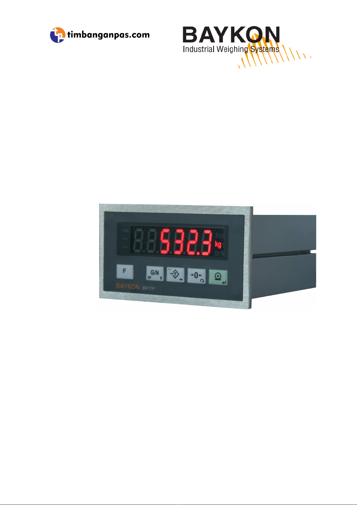
F gure 2.1
- Front panel view of BX11
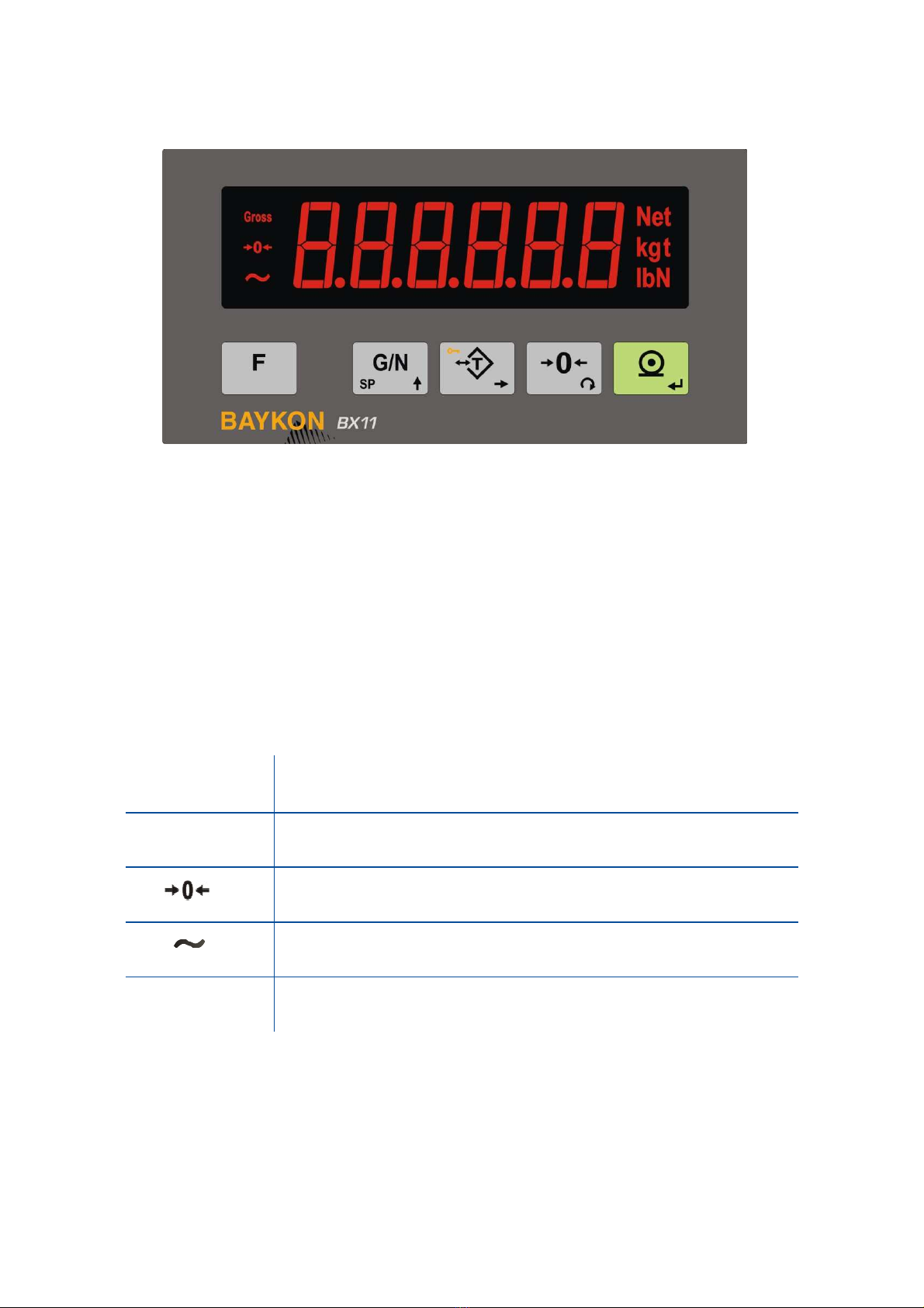
2.1 D splay
The wei ht display of BX11 is seven se ments LED. At the ri ht side of the display there are three
LED’s for indicatin the net, ross and the unit ( standard k ). The meanin s of the announcement
LED’s on the display are:
Gross
Announces the indicated value is the ross wei ht.
Net
Announces the indicated value is the net wei ht.
Announces the wei ht is in the center of zero.
Announces the wei ht value on the display is unstable.
Un ts
, k , t, lb, klb, N, kN units are located on the ri ht of the
display.

BX11 Smart Process Indicator, User Manual, Rev. 1.8, May 2017
Pa e
5
of
48
2.2 Key Pad
The keys and the key functions of BX11 are:
Funct on:
Key function is pro rammable to Increased Indication, Total, Tare value
indication, CN value indication, Peak function and Hold function at parameter [ 116 ].
GN / Set Po nt: Pressin this key indicates the Gross wei ht temporarily. Press lon
time to enter the setpoint menu.
Tare / Clear
:
Pressin this key tares the scale and et into the Net mode.
Press lon
time to clear the tare.
Zero ng:
In Gross mode, if the scale doesn’t show zero while there is no load on the
pan, you can zero the scale by pressin this key.
Pr nt:
By pressin this key wei ht data and other information dependin on the setup
parameters sent to a printer or a PC via serial port.
2.3 Key Lock
BX11 has ability to lock the keys to avoid unauthorized person’s interfere. The key(s) which would
be locked are pro rammed at parameter [ 115 ].
You can activate or deactivate this function by lon pressin <F> key, press <Tare/Clear> and
<Pr nt> keys sequentially. [ Lock ] prompt appear for a short while to indicate the pressed key is
locked.

BX11 Smart Process Indicator, User Manual, Rev. 1.8, May 2017
Pa e
6
of
48
3. O
PERATION
3.1 Bas c We gh ng
Zero ng
Zeroin corrects the drifts of the unloaded scale from the zero point. Zeroin ran e is limited in the
instrument in set up mode. Refer to technical manual for details on zeroin limits.
1. Unload the scale.
2. Press < Zero > key.
3. Centre of zero appears symbol on the display.
4. Check the center of zero si n on the left of the display. If it is not appears, press < Zero >
key once more for correct zeroin .
We gh ng
1. Press < Zero > key, if [ 0.00 k ] is not displayed at unloaded scale.
2. Place wei hin item on the scale.
3. Wait until the motion annunciator disappears from the display.
4. Read the wei hin result.
If the loadin is out of the indication ran e the prompts below are displayed.
Under of ne ative indication limit Over than positive indication limit
Net we gh ng n the conta ner
Tarin is used to wei ht material in the container at basic wei hin operation.
1. Place the empty container on to the scale and press <Tare> key.
2. The display is zeroed and the NET symbol appears. Check
si n on the display. If it is not
appears, press the <Tare> key once more for correct tarin .
3. Add the material into the container and follow its wei ht in net.
Clear ng the tare
Lon press <Tare> key in net mode. The NET symbol disappears and Gross symbol appears on
the display to ether with the ross wei ht indication.
Automat c tar ng
The scale tares automatically and NET is displayed, after placin a wei ht on the empty scale, if this
feature is enabled. Refer to parameter [ 043 ]. The wei ht should be heavier than the value entered
to the parameter [ 042 ] for automatic tarin .

BX11 Smart Process Indicator, User Manual, Rev. 1.8, May 2017
Pa e
7
of
48
Automat c clear
The tare is automatically cleared after emptyin the scale, if this feature is enabled. Refer to
parameter [ 113 ].
Automat c zero po nt correct on
Zero point is corrected automatically for minor deviations if the chan e is within the ran e of limited
zeroin ran e value. Disable this correction at the applications like tank wei hin , batchin , fillin
etc. a ainst wron zeroin at feedin . Refer to Automatic Zero Trackin parameter [ 214 ].
Automatic zero point correction ran e is limited to ether with zeroin ran e above.
Automat c zero at power on
Warning: Automatic zeroin at power on can be enabled only if the scale is always unloaded
before power on. This function should be disabled at tank / silo wei hin applications.
Zero point is corrected automatically at power on the instrument to compensate zero drifts of the
scale if the scale is always power on when unloaded. This feature should be disabled for tank, silo,
hopper scales etc.
Power on zero has a limited ran e and the instrument announces [ E E E ] error prompt in case of
out of ran e. Press < F > key to read the residual drift and to start indication without zeroin and
call service.
Restore Tare at Power on
This function saves the tare at power off and the instrument start to operate Net after power on as
before power off. This feature should be enabled, if tarin is used at tank wei hin applications.
Refer to parameter [ 112 ].
Pr nt ng
Press < Pr nt > key when the item is on the pan and wei ht is stable to print the label. Refer to
Page 36 for details.
BX11 Smart Process Indicator, User Manual, Rev. 1.8, May 2017
Pa e
8
of
48
3.2 Advanced Funct ons
Force measurement
The instrument should be set to force mode for the bidirectional force measurement from
–Maximum to +Maximum. The force unit N or kN can be displayed. BX11 is very fast force
measurement instrument with its hi h conversion rate, up to 1600. Refer to parameter [ 210 ].
H gh resolut on ( Default )
If you pro ram < F > key for hi h resolution, the wei ht value is displayed 10 times hi her
resolution temporary 5 seconds.
Temporary Gross nd cat on n Net
Pressin < G/N > key indicates the Gross wei ht temporarily for 5 seconds in Net mode.
Total
If you pro ram < F > key for totalization, the printed wei hts are accumulated and displayed by
pressin < F > key. Press < Pr nt > key to transfer total or press < Zero > key to erase the total
while the total is displayin .
Funct onal cutoff outputs
The instrument can be set to various basic setpoint functions like absolute, numerical, control
outputs. Refer to Page 16 for details. Besides these basic functions you may set di ital outputs for
usa e at various applications easily. This feature of instrument eliminates PLC from control
cabinets. Below you will find some examples of BX11 advanced setpoint functions.
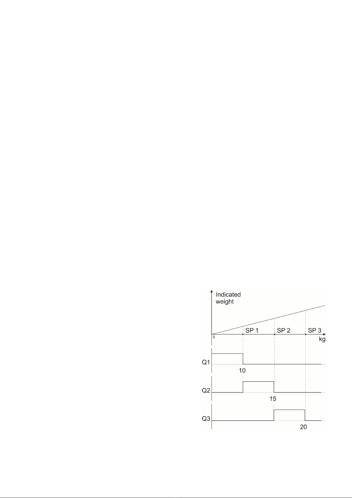
Example 1: Bas c F ll ng. 3 speed. if you want
wei ht the hopper for fillin the container or ba , you
may set the setpoints to Control mode-2. After
enterin the coarse, medium and fine speeds cutoff
points to SP1, SP2 and SP3 in sequence, outputs will
chan e as shown on the ri ht to fill 20 k ba s
basically.
BX11 Smart Process Indicator, User Manual, Rev. 1.8, May 2017
Pa e
9
of
48
Example 2: Sort ng or Checkwe gh ng. if you want
checkwei hin or sortin the items basically, you
may set the setpoints to Control mode-1. After
enterin the sortin wei hts to SP1, SP2 and SP3 in
sequence, outputs will chan e as shown on the ri ht.
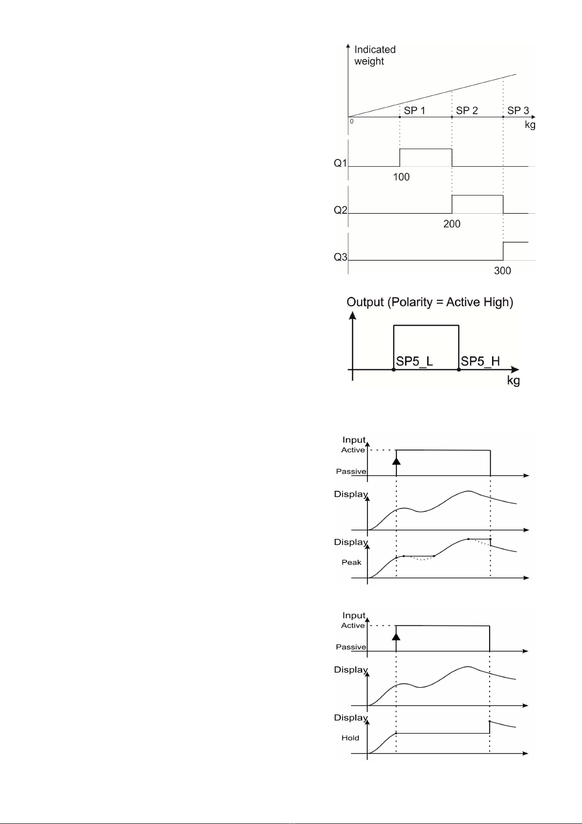
Examp
le 3:
Produc ng alarm.
if you want to produce
alarm si nal between to wei ht values, e. . between
200.0 and 300.0 k , additional to your other cutoff
needs, you may set setpoint 5 to functional output
and active window. After enterin SP5L = 200.0 and
SP5H=300.0, the di ital output will be as shown on
the ri ht to control valves, lambs etc.
Peak Hold
BX11 has ability to hold the peak of the loadin durin
the di ital input active, if pro rammed. After applyin
the di ital input, the instrument follows the loadin to
hold its peak and displayed wei ht / force increases
to ether with increasin loadin . Holds the peak
followin hi her loadin s as shown on the drawin .
Hold D splayed value
BX11 has ability to hold the displayed value durin the
di ital input active, if pro rammed. Durin the di ital
input, the instrument holds the displayed value, even
the loadin chan es as shown on the drawin .

BX11 Smart Process Indicator, User Manual, Rev. 1.8, May 2017
Pa e
10
of
48
4. I
NSTALLATION
PRECAUTION: Please read this section carefully before installation of the instrument. Applying the
recommendations in this section will increase your system reliability and long term performance.
4.1 Recommendat ons
Control Cab net Des gn
Warning: Please care the following warnings for designing the control cabinet which will increase
your system reliability.
The control cabinet should be desi ned so that Analo Di itizer can operate safely. The panel
should be placed clean area, not ettin direct sun li ht if possible, with a temperature between
-15 ºC and +55 ºC, humidity not exceedin 85% non-condensin . All external cables should be
installed safely to avoid mechanical dama es.
BX11 instruments are very low level si nal measurin instruments. To avoid electrical noise, BX11
should be separated from the equipments that produce electrical noise. Preferable use metal
cabinet a ainst radio frequency interference and the cabinet shall be connected to round a ainst
the electroma netic disturbances. Load cell cable trays must be separated from others, if possible.
If there are noise- eneratin equipments such as heavy load switches, motor control equipments,
inductive loads etc., please be careful a ainst the EMC interference in the cabinet. If possible
protect BX11 instruments with the faraday ca e or install them in separate section or install them
far a way from this kind of equipments. Connect parallel reverse diodes to the DC inductive loads
like relays, solenoids etc. to minimize volta e peaks on the DC power lines.
Cabl ng
All cables comin to the control cabinet shall be shielded. Please use separate cable tray for these
low si nal level cables. Distance from load cell cables, interface cables and DC power supply cables
to power line cables shall be minimum 50 cm.
Warning: Please always remember that BX11 instruments are very low voltage measuring
instruments. Your control cabinet design and proper installation increases reliability and
performance of the instrument. Please do not forget that the instrument must be powered off before
inserting or removing any peripheral connector.
4.2 How to nstall the nstrument and Scale ?
Please follow the installation and commissionin steps described below carefully to prevent
unwanted results after installation.

BX11 Smart Process Indicator, User Manual, Rev. 1.8, May 2017
Pa e
11
of
48
Step 1. Mechan cal Installat on
Take care to the housin dimensions and the su ested panel hole dimensions iven in the Page
2. Install the indicator on the panel with its panel fixin accessories. Be sure, all mechanical
installation of your mechanical system and panel are finalizin before startin the next step.
Step 2. Load Cell Connect on
Warning: After load cell connection to the instrument, the welding on the mechanical constriction is
not recommended. Disconnect all connectors from indicator before welding on the mechanical
hardware.
Load cell connection detail is shown in Fi ure 4.1. In 4-wire installations the sense and excitation
pins with the same polarity should be short c rcu ted at the connector side. If you have junction
box, use 6 wire cable between BX11 and the junction box, and short circuit these pins at junction
box for better performance.
4 w re LC connect on
6 w re LC connect on
F gure 4.1
-
Load cell connections
Warning: Always connect Sense pins to Excitation pins for wire connection. Non-connected
sense pins may cause the wrong Excitation voltage measurement and create an accuracy problem.
Warning: Connect the load cell cable shield to the reference ground or shield pin of the load cell
connector.
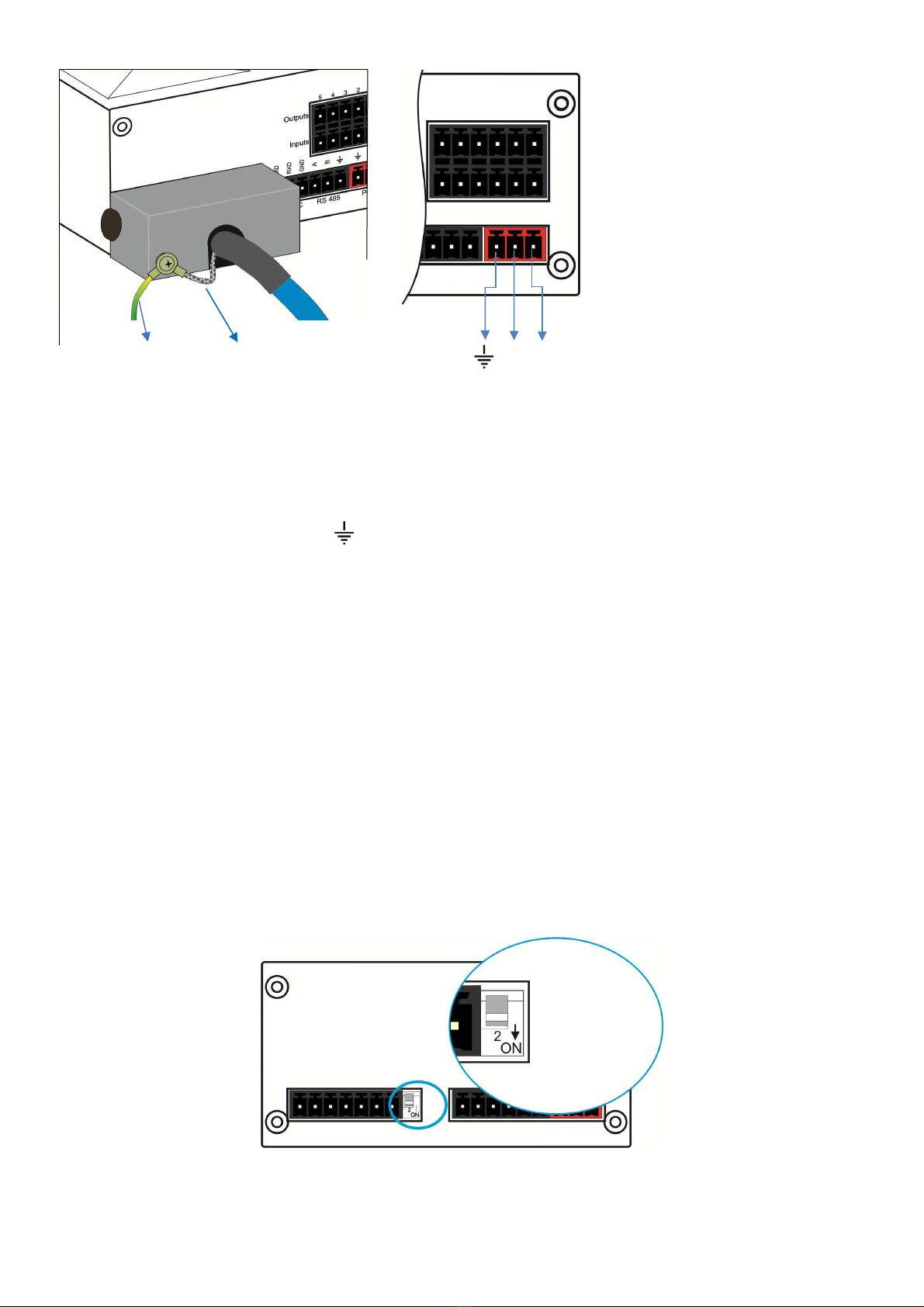
Step 3. Power Supply Connect on and Ground ng
The quality of the instrument’s round will determine the accuracy and the safety of your measurin
system. A proper round connection is needed to minimize extraneous electrical noise effects on
the measurement. A poor round can result in an unsafe and unstable operation. It is important that
the instrument should not share power lines with noise- eneratin parts such as heavy load
switchin relays, motor control equipments, inductive loads, etc. If the condition of the power line in
the plant is poor, prepare a special power line and roundin .
Power supply volta e of the instrument shall be between 12 VDC and 28 VDC. The pin confi uration
of the 24 VDC power supply connector located ri ht - bottom of the instrument is shown in Fi ure
4.2 below. Be sure, the power supply is switched of before connection.
BX11 Smart Process Indicator, User Manual, Rev. 1.8, May 2017
Pa e
12
of
48
The pin layout of the
24VDC connector of
BX11 Series
( rear view )
PE Protective Loadcell
0V 24V
roundin cable shield
F gure 4.2
-
The pin layout of 24VDC connector
Warning: Before interfering the instrument, turn off the power and wait at least for 30 seconds.
Warning: Connect the grounding pin to the reference ground.
Step 4. Energ ze the nstrument
Check the mechanical installation, roundin , load cell connection and power supply connection to
be sure the correct electrical installation before ener izin the instrument. If before steps are done
properly ener ize the instrument.
Step 5. Set the cal brat on sw tch to programm ng and cal brat on
Warning : If the scale is sealed before, call the authorized person before interfering the scale.
If there is a DIP switch on BX11’s rear side and its position should be “ON” ( downward ) to chan e
the metrolo ical related parameters includin calibration. No need to open the housin to chan e
the position of this DIP switch.
F gure 4.3
- The location of calibration DIP switch

BX11 Smart Process Indicator, User Manual, Rev. 1.8, May 2017
Pa e
13
of
48
Step 6. Programm ng
You will pro ram the instrument accordin to your application in this step. Adjust;
•Interface parameters in block [ 00- ] RS232 and [ 01- ] RS485 serial ports,
•Confi uration parameters in block [ 1-- ] for scale functions related with application like
savin tare before power off and restart in Net mode and di ital I/O related entries.
•Set up parameters to set up the scale in block [ 2-- ] like zeroin ran e. Please remember
these parameter values are restricted for scale usa e in trade. You have to enter the scale
capacity and division values in this block.
Warning: The programming and parameter descriptions are referred in Page 23. We recommend
you to save these parameters before next step against to lost the adjustments in this step if
calibration can not performed somehow.
Step 7. Cal brat on
You will calibrate the scale after pro rammin the parameters. You may follow one the calibration
methods below.
•eCal Electronic calibration without test wei ht
need via IndFace1x or fieldbus ( Page 26 ).
•Full calibration via keys on the instrument by usin test wei ht. Refer to Page 26.
•Zero adjustment and span adjustment in sequence via keys or fieldbus. Span calibration is
needed test wei ht. You may save the zero adjustment before startin span adjustment.
Refer to Page 28.
•Zero adjustment and span adjustment under load in sequence via keys if the scale cannot be
emptied when the span adjustment is performed. Need test wei ht for span calibration. Refer
to Page 28.
You may access to the calibration menu from operation menu by followin the description in fast
access to the calibration section ( Page 27 ). After the calibration o back to the operation menu
after savin adjustment ( Refer to Page 23 )
Remember: You may use parameter 905 to follow the load cell output voltage on loading, if you can
not perform the calibration.
Step 8. Test ng the scale performance
You have to check your scale performance by testin the scale eccentricity, scale linearity at loadin
until maximum loadin value and unloadin , repeatability etc. before usin it. If testin results are
not in your limits recheck the steps above and your hardware to find the error source.
Step 9. Br ng the DIP sw tch to up pos t on to unlock the scale adjustment
If the DIP switch is brin to the downward position for pro rammin , push it to the upward position
to lock the scale adjustment a ainst interferin the un-authorized persons in to the scale. If the
scale is used in non-trade industrial wei hin , this step is not must.
Warning: If the scale is used in trade, the scale should be sealed after bringing the DIP switch to
the upward position sealed before. Call the authorized person for sealing the scale, if need be.

BX11 Smart Process Indicator, User Manual, Rev. 1.8, May 2017
Pa e
14
of
48
Step 10. Per pheral related parameters programm ng, f any
If you will connect any peripheral to the instrument, you have to set the related parameters up.
Refer to Page 1 for di ital input/output, Page 29 for analo output pro rammin and technical
manual for fieldbus interfacin .
Step 11. Per pheral connect ons
If you will make any peripheral connection like di ital input, di ital output, RS232, RS485 and
fieldbus etc. switched off the power supply and connect you peripheral as described below and in
the related section of this manual. You will find detailed description on the peripheral connection
and interfacin details in the BX11 technical manual.
Important: Powered off the instrument before any connector installing to the instrument.
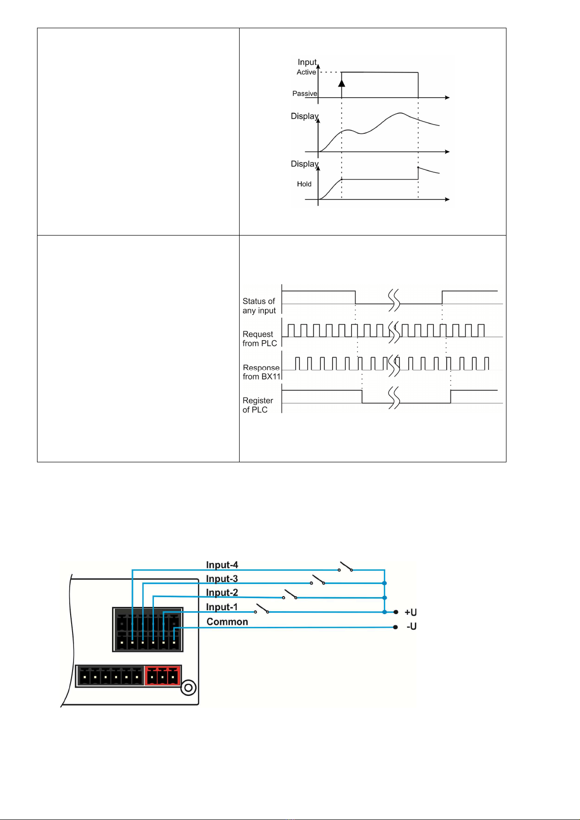
D g tal Input Connect on
BX11 inputs which are independently pro rammable for zeroin , tarin , clear, print, key lock, peak,
hold, and as a fieldbus input port. If the input is pro rammed as a fieldbus input port, the input
status is transferred to the PLC by fieldbus command.
Inputs are 12~28 VDC,10 mA.
Key funct ons v a nputs
Zero ng, Tar ng, Clear, Pr nt
The key functions are executed via
di ital inputs. Tarin via di ital input is
shown in the drawin as an example.
Refer to parameter [131, 132, 133
and 134 ] on Page 30.
Peak hold
The instrument follows the peak of the
loadin durin the active peak input.
Low input si nal allows the basic
wei hin operation.
Fieldbus interfaces have peak hold
command.
Refer to parameter [
131, 132, 133
and 134 ] on Page 30 and commands
of interfaces.
BX11 Smart Process Indicator, User Manual, Rev. 1.8, May 2017
Pa e
15
of
48
Hold
The instrument holds the wei ht
indication durin input si nal which
help the measured value to the
operator for a while. Low input
si nal allows the basic wei hin
operation.
Refer to parameter [131, 132, 133
and 134 ] on Page 30.
PLC remote port
The di ital input of the wei hin
instrument is used as
a remote port of
the PLC if the input is pro rammed as
fieldbus port.
The instrument transfers the status of
the input port to the PLC after
receivin the related command. PLC
processes the received data as a
remote di ital input port.
Refer to parameter [
131, 132, 133
and 134 ] on Page 30.
Inputs connection dia ram is shown in Fi ure 4.4.
F gure 4.4
-
BX11 Inputs connection dia ram
BX11 Smart Process Indicator, User Manual, Rev. 1.8, May 2017
Pa e
16
of
48
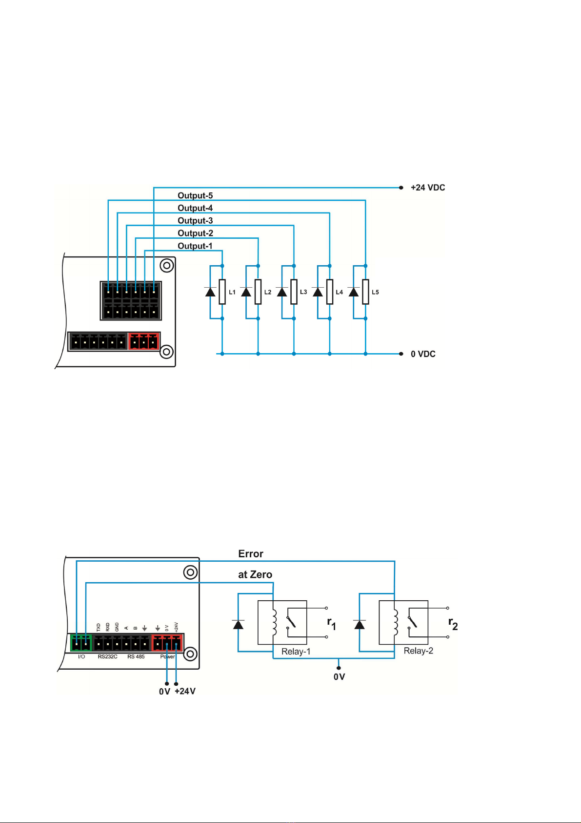
D g tal Output Connect on
BX11 instruments di ital outputs are can be used as a standard, threshold and window. Threshold
and window outputs are also pro rammable positive or ne ative polarity. Di ital outputs of BX11 are
also pro rammable as a fieldbus port to control them with a fieldbus commands. Refer to parameter
[ 117 ], [ 130 ] and [ 70- ].
Outputs connection dia ram is shown in Fi ure 4.5 and Fi ure 4.6.
F gure 4.5
- BX11 Outputs connection dia ram
Non-isolated outputs are power supply volta e – 1.5V, 100mA. Connection dia ram is shown in
Fi ure 4.6.
F gure 4.6
- Non-isolated outputs connection dia ram
Outputs are
30 VDC, 1A
.
BX11 Smart Process Indicator, User Manual, Rev. 1.8, May 2017
Pa e
17
of
48
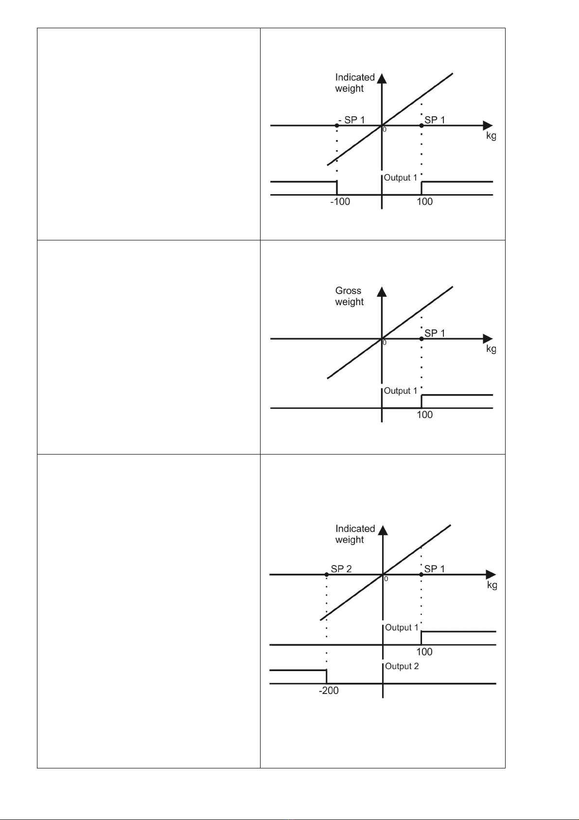
Setpo nt of absolute nd cated we ght
The absolute indicated wei ht value is
compared with the setpoint entry and the
output state is activated if the absolute
wei ht is hi her than setpoint. As an
example, setpoint 1 is 100 k in the
drawin on the ri ht.
Refer to parameter [ 130 ]=1,2,3,4 on
Page 29.
Setpo nt of gross we ght
The output state is activated durin the
hea
vier ross loadin s at ross or net
wei ht indications. This feature can be
used to produce alarm si nal at empty or
over wei hted scales, tanks etc. As an
example, setpoint 1 is 100 k in the
drawin on the ri ht.
Refer to parameter [ 130 ] on Page 29.
Setpo nt of real nd cated we ght
The + or - si n of the setpoint can be
entered. The output si nal is produced if ;
Positive setpoint : The output is activated if
the wei ht is heavier than the loadin .
Refer to setpoint 1 in the drawin .
Ne ative setpoint : The output is activated
if the ne ative net wei ht is li hter than
the setpoint. Refer to setpoint 2 in the
drawin .
As an example, setpoint 1 is 100 k and
setpoint 2 is -200 k in the drawin on the
ri ht.
To enter the ne ative or positive value,
lon press < Tare > key while the set
point value is seen on the display.
Refer to parameter [ 130 ] on Page 29.
BX11 Smart Process Indicator, User Manual, Rev. 1.8, May 2017
Pa e
18
of
48
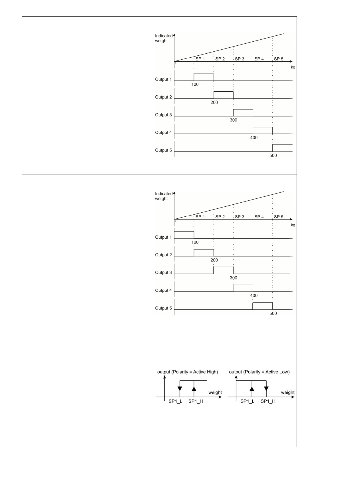
Control Mode-1:
Setpoints are entered as
SP1<SP2<SP3<SP4<SP5
and outputs are activated as indicated in
the drawin as seen on the ri ht. This
mode can be used for checkwei hin ,
sortin , fillin , multicomponent batchin
etc.
Refer to parameter [ 130 ] on Page 29.
Control Mode-2:
Setpoints are entered as
SP1<SP2<SP3<SP4<SP5
and outputs are activated as indicated in
the drawin as seen on the ri ht. This
mode can be used for checkwei hin ,
sortin , fillin , multicomponent batchin
etc.
Refer to parameter [ 130 ] on Page 29.
Threshold Output:
2 set point values are entered. SP1 is the
point that the output oes active when the
wei ht increased from SP1_H. SP1_L is
the point that the output drops to passive
state when the wei ht decreased to
SP1_L.
Inverse function is available.
Refer to parameter [ 7-- ] on Page 30.
Other manuals for BX11
1
This manual suits for next models
13
Table of contents


