Anywire ASLINK BL2109-0 Series User manual

BL2109-0□-22
Branching Unit (IP67)
AnyWireASLINK System Products Guide
■Function List
[Type]
-BL21090*22 1/8-
BL2109-08-22 8 ports
BL2109-04-22 4 ports
4 ports
8 ports IP67
is a registered trademark of OMRON Corporation.
This Products Guide is a document that describes individual products. Read it carefully to understand the products.
Product Specications Waterproof
Branching unit with M12
Smartclick connector
[Notes on Safety]
Precautions that must be observed in order to use this system safely are indicated as shown below.
You must observe these precautions.
[Warranty]
WARNING CAUTION
WARNING
○
○
○
○
○
○
○
○
○
CAUTION
■
■
■
A WARNING indicates a potentially hazardous
situation which, if not handled correctly, could
result in death or serious injury.
System Safety
This system is intended for general industrial applications. It does not have functions for supporting applications requiring higher levels
of safety such as safety-related devices or accident prevention systems. The product must not be used for these purposes.
Always turn off the power in installing or replacing the system.
Prolonged continuous ow of a rated load current or higher or a transit current due to load short-circuit, etc., in the hybrid unit including
the output unit and the output circuit may result in smoking or ring. An external safety device such as a fuse must be installed.
System power supply
Use a stable, 24V DC power supply. Use of an unstable power supply may cause problems with the system.
Separately route high-voltage and power cables
Although the AnyWireASLINK has a high noise margin, install the transmission line and I/O cables away from high-voltage and power
cables.
Connectors and terminals
-Pay careful attention to the length and installation of cable wiring to ensure that connectors and cables are neither overloaded nor disconnected.
-
Make sure to prevent any metal objects from getting inside the connectors or the terminal blocks.
-
Short-circuits caused by metal objects or mis-wiring are likely to damage the device.
Do not impose any external loads on the units. Doing so may cause a failure.
Do not disconnect or reconnect between the transmission line and slave units when the transmission line is active. A malfunction may occur.
Use the AnyWireASLINK within the range of the specications and conditions shown below.
Warranty period
The warranty on the delivered Product shall continue to be effective for one (1) year after the delivery thereof to a location as designated by
the original owner.
Scope of warranty
Should a defect occur in any part of the Product during the foregoing warranty period when it is used normally in accordance with the
specications described in this Products Guide, the Company shall replace or repair the defect free of charge, except when it arises as a result of:
[1] Misuse or abuse of the Product by the owner;
[2] Fault caused by other than the delivered Product;
[3] The unauthorized modication or repair of the Product by any person other than the Company’s personnel;
[4] Any unusual force of nature, disaster or other cause beyond the Company’s control.
The term “warranty,” as used herein, refers to the warranty applicable to the delivered product alone. The Company shall not be liable for
consequential or incidental damages resulting from any malfunction.
Repair at cost
After the expiration of the warranty period, the owner shall be responsible for all costs and expenses incurred for the troubleshooting and
repair of the Product. Even during the warranty term, the Company shall repair any defects arising from causes other than within the scope
of the warranty as specied above, at the owner’s cost.
A CAUTION indicates a potentially hazardous situation
which, if not handled correctly, may result in personal
injury or property damage.

To connect loads (e.g. I/O ports) that are
controlled with a power supply other than the
one used for the AnyWireASLINK system,
always use a 4-wire (isolated) terminal.
Otherwise, malfunction may be caused.
-BL21090*22 2/8-
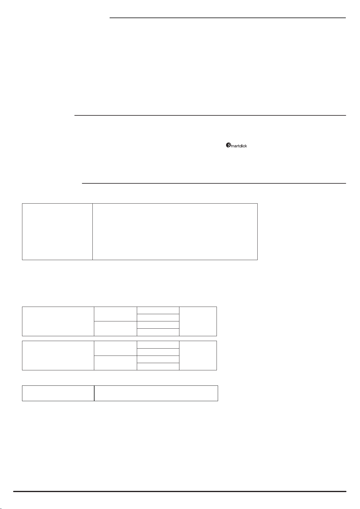
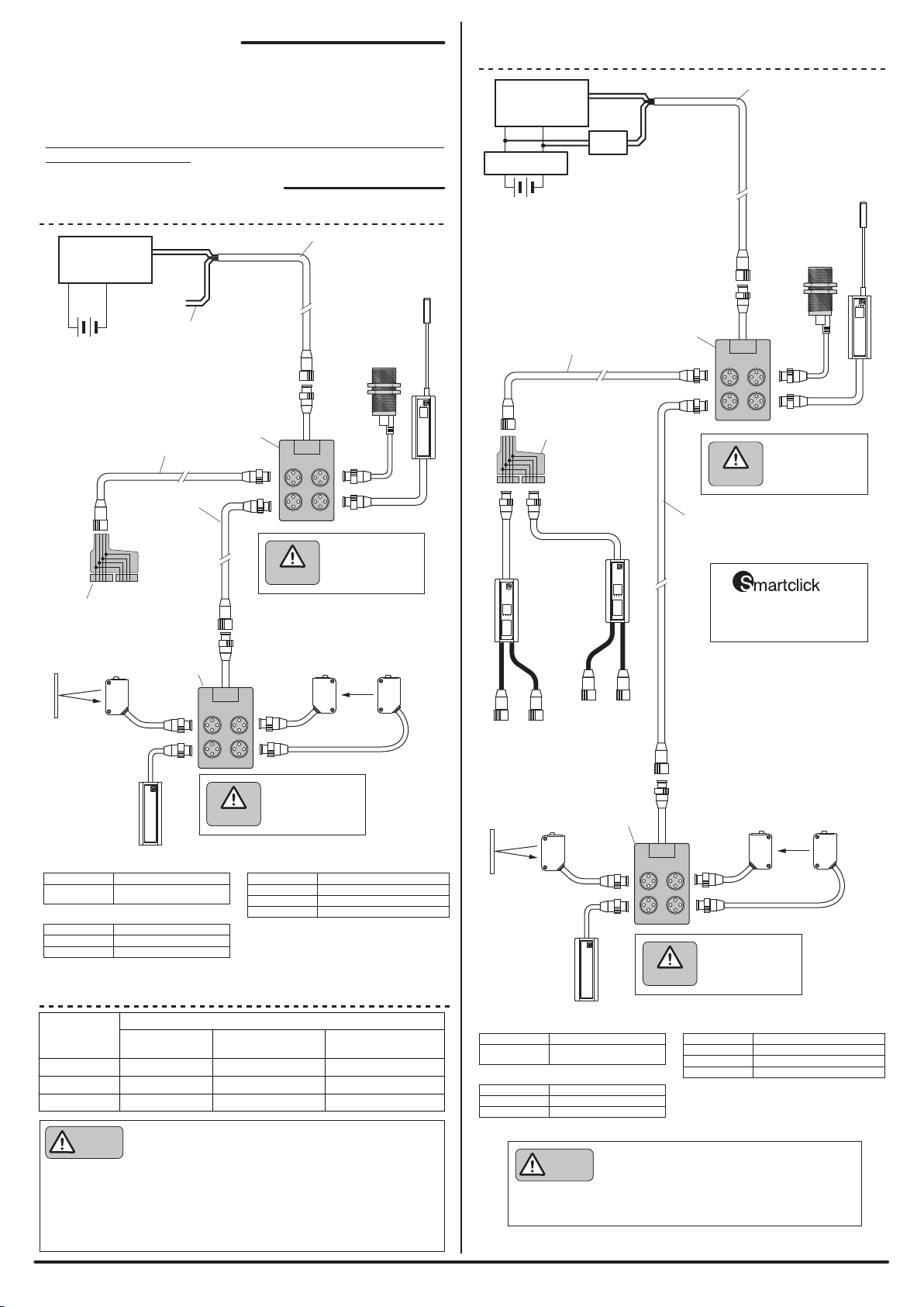
■Example of mixed installation with 2-wire (non-isolated) and
4-wire (isolated) terminals
■
Connection with a 2-wire (non-isolated) terminal only
BL2-1S1P-3K
BL2-1S1P-5K
BL2-1S1P-10K
B Waterproof trunk cable (1.25mm2)
A Waterproof trunk cable (1.25mm2)
BL2-0C1S-3K Loose wires on one end,
straight M12, 3m
Model Description
Model Description
4 ports
8 ports
Model Description
Straight M12 on both ends, 3m
Straight M12 on both ends, 5m
Straight M12 on both ends, 10m
C Waterproof branching unit
BL2109-04-22
BL2109-08-22
Brown White
A
B
C
×
×
A
B
BC
ASLINK
TERMINATOR (IP67)
ASLINK
TERMINATOR (IP67)
ASLINKER
(IP67)
Compact 2-point
I/O terminal
C
C
Y-Joint Plug/Socket
XS5R-D426-5 (OMRON Corporation)
Y-Joint Plug/Socket
XS5R-D426-5
(OMRON Corporation)
ASLINKSENSOR
Retroreective type (IP67)
ASLINKSENSOR
Retroreective type (IP67)
ASLINKSENSOR
Transmissive type (IP67)
ASLINKSENSOR
Transmissive type (IP67)
B
[AnyWireASLINK Terminal]
[System Configuration Example]
The AnyWireASLINK can employ a two-wire or four-wire terminal selectively depending
on the load current. If the load current is small, using a two-wire (non-isolated) terminal
allows for achieving simplied wiring without local power supply.
In the case of prioritizing the sites of concentrated loads and/or the number of
connections, hybridization with a four-wire (isolated) terminal, which supports local
power supply, is also possible.
Make sure to use a four-wire (isolated) terminal in the case of input and load driving
using an external power supply.
Black: DN
Red: DP
Brown White
Black: DN
Red: DP
AnyWireASLINK
master
AnyWireASLINK
master
24V DC*
24V DC*
*Make sure to use a 24V DC stabilized power supply
for the power supply to be connected.
*When complying with the UL Standard, make sure
to use a 24V DC stabilized power supply of “NEC
Class 2 Output.”
Open power lines (brown & white)
Protect these lines so that they won’t
come in contact with other devices.
ASLINKSENSOR
Proximity type
(amplier relay type) (IP67)
ASLINKSENSOR
Proximity type
(amplier relay type) (IP67)
ASLINKSENSOR
Proximity type (IP67)
ASLINKSENSOR
Proximity type (IP67)
CAUTION
General-purpose
sensors cannot be
connected to the
branching unit.
CAUTION
General-purpose
sensors cannot be
connected to the
branching unit.
CAUTION
CAUTION
Supply current on the transmission line (DP, DN)
Size of
the transmission
line (DP, DN)
1.25mm2
0.75mm2
MAX 2A
MAX 1.2A
■
Relationship between the size and length of
the transmission line and the supply current (Table 1)
MAX 0.5A
MAX 0.3A
MAX 1A
MAX 0.6A
0.5mm2MAX 0.8A MAX 0.2AMAX 0.4A
Total length:
50m or less
Total length: Over 50m,
no longer than 100m
Total length: Over 100m,
no longer than 200m
- Connect the same symbols (DP, DN) correctly between the AnyWireASLINK
master and each device.
- The branching length or branch number has no limitation.
- Include the length of the cable provided with the terminal in the “total line length.”
- Connect the terminator BT0 (with polarity) on the transmission line terminal
farthest from the AnyWireASLINK master unit.
- Refer to Table 1 so that the size and length of the transmission
line and the allowable supply current lie within an appropriate
range. CAUTION
ASLINK
lter
General-purpose
power supply lter
CAUTION
General-purpose
sensor, actuator, etc.
General-purpose
sensor, actuator, etc.
1: 24V
2: DP
3: 0V
4: DN
1: 24V
2: DP
3: 0V
4: DN
General-purpose
sensors cannot be
connected to the
branching unit.
General-purpose
sensors cannot be
connected to the
branching unit.
The M12 connector is
Smartclick-compatible.

[Name of Each Part]
-BL21090*22 3/8-
1
2
3
4
24V
DP
0V
DN
1
2
4
3
1
2
3
4
24V
DP
0V
DN
1
2
4
3
UL style 2464
VVC AWG16 × 4C, φ8.2, Black
IP67LK-CAB-13252A
UL style 2464
VVC AWG16 × 4C, φ8.2, Black
IP67LK-CAB-13252A
XS5H
XS5H
M4 screw hole*2
M4 screw hole*2
M4 screw hole*2
M4 screw hole*2
Transmission
cable
Transmission
cable
Color: Warm gray
Color: Warm gray

-BL21090*22 4/8-
■BL2109-04-22 ■BL2109-08-22
1
2
3
45
1
2
3
45
1
2
3
45
1
2
3
45
4
3
2
1
1
2
3
4
1
2
3
4
24V
DP
0V
DN
1
2
3
45
1
2
3
45
1
2
3
45
1
2
3
45
8
7
6
5
1
2
3
45
1
2
3
45
1
2
3
45
1
2
3
45
4
3
2
1
1
2
3
4
1
2
3
4
24V
DP
0V
DN
*
Pin #5 is open.
[Internal Circuits]

-BL21090*22 5/8-
[Engagement]
Insertion and removal
Locking force
Withstand 50 cycles
0.1 to 0.25N·m
■Individual Specications
■Connector specications
DP-DN permissive current
BL2109-08-22
1 port
2A or less
Port 1 to 8 total
BL2109-04-22
1 port
Port 1 to 4 total
24V-0V permissive current
BL2109-08-22
1 port
4A or less
Port 1 to 8 total
BL2109-04-22
1 port
Port 1 to 4 total
is a registered trademark of OMRON Corporation.
Service power supply voltage
Ambient temperature use
Ambient humidity use
Temperature/humidity storage
Atmosphere
Altitude use*1
Pollution level*2
Noise resistance
Withstand voltage
■General Specications
24V DC +15% to -10% (21.6 to 27.6V DC) with a ripple of 0.5Vp-p or less
0 – +55°C
10 – 90%RH No condensation
-25 – +75°C
No corrosive gas
0 – 2000m
2 or less
1200Vp-p (pulse width 1μs)
1000V AC
*1 Do not use or store AnyWireASLINK devices in an environment where the pressure exceeds
the atmospheric pressure at an altitude of 0 meters. Doing so may result in malfunction.
*2“Pollution level” is an index that indicates the degree of occurrence of conductive substances
in the environment where the device is used.
Pollution level 2 means the occurrence of only pollution by non-conductive substances.
In such an environment, however, electrical conduction could occur due to accidental
condensation.
[Installation Location]
- Locations where this product is not directly subject to vibration or shock
- Locations where this product is not directly exposed to dust
- Locations where this product is not directly exposed to conductors, such as metal chips or spatters
- Locations without condensation
- Locations where the atmosphere is free of corrosive gases, ammable gases, and sulfur
- Locations far from high-voltage or high-current cables
- Locations far from servos, inverters, and other cables and controllers that generate high-frequency noise
To engage the Smartclick connector, insert the plug deep into the socket and then turn it clockwise by about 45 degrees until
it clicks.
[Specifications]

-BL21090*22 6/8-
(1000) 90.5
50
25.5
20
1
2
3
4
24V
DP
0V
DN
1
2
4
3
4
12
3
A
B
■BL2109-04-22
1
2
3
4
24V
DP
0V
DN
AWG16
φ8.2
42
33 9
4.2 73
φ9 countersink,
depth 11
2-R2.25
Lot No. label
φ4.5 drilling
Unit: mm
Arrow A view
Arrow B view
[Outside Dimensions]

-BL21090*22 7/8-
■BL2109-08-22
Lot No. label
(1000) 135.5
50
25.5
20
1
2
3
4
24V
DP
0V
DN
1
2
4
3
4
12
3
A
Arrow A view
Arrow B view
B
1
2
3
4
24V
DP
0V
DN
AWG16
φ8.2
42
33 9
4.2
2-R2.25
77.3 34
2-φ9 countersink,
depth 11
2-φ4.5 drilling
Unit: mm

Printed in Japan 2017 UMA-17798B-EN
-BL21090*22 8/8-
Anywire Corporation
Headquarters :1 Babazusho, Nagaokakyo-shi, Kyoto 617-8550 JAPAN
:Contact by website http://www.anywire.jp
[Address]
This manual suits for next models
2
Table of contents
Other Anywire Accessories manuals
Popular Accessories manuals by other brands

RAB Lighting
RAB Lighting Lightcloud LCLCSENSE manual

Me
Me inertialSENSOR ACC5703 operating instructions

MCS
MCS ITalks ERS Series manual

JK Audio
JK Audio BlueDriver-M3 user guide

PCB Piezotronics
PCB Piezotronics IMI SENSORS TO640B11 Installation and operating manual

CTI
CTI SD2-NH3 Installation and operation manual