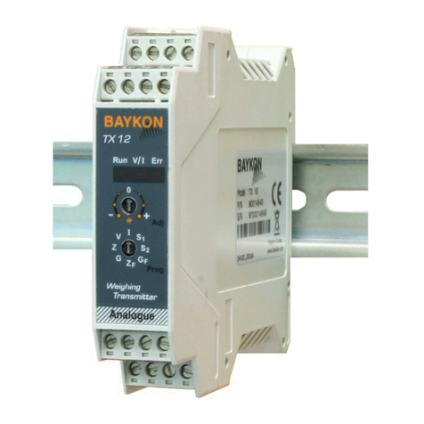
BAYKON TX 1 Quick start guide

T
X 1
WEIGHT TRANSMITTER
OPERATIONAL MANUAL
08/2012

1
WARNING !
The Error LED can be active before calibration. Do not care the error status
before performing the calibration of your weighing system.
Contents :
SECTION
CONTENTS PAGE
1. Features 2
2. Installation and Commissioning 3
2.1 Mechanical Installation 3
2.2 Electrical Connections 3
2.3 Load Cell Connection 4
2.4 Analogue Output Connection 5
2.5 Input and Outputs ( only TX 1W ) 5
2.6 Serial port RS232C ( only TX 1W ) 5
2.7 Commissioning 6
3. Operation 6
4. Programming via Keys 6
4.1 Changing the Analogue Output Mode 7
4.2 Setup and Calibration 7
5. Programming by PC software 10
6. Housing Dimensions 11
7. Trouble Shooting 11
PRECAUTIONS
Don’t let unauthorized people interfere with the instrument.
Check the supply voltage, the load cell and especially the ground
connections before energizing TX 1.
Don’t energize TX 1 before making the load cell connection.
Don’t connect / disconnect the cables and/or connectors while TX 1 is
energized.
Do not open the enclosure while TX 1 is connected to the power supply.

2
1. Features
The amplifier type TX 1 is an accurate and economic load cell transmitter, easy to
integrate into process control systems. By its “digital heart” – modern microcontroller
technology – type TX 1 allows a comfortable calibration and set up with a combination of
LED’s and push buttons. Option equipped TX 1 can be programmed and calibrated via PC
software xFace.
The analogue signal output is programmable to 0 – 10 V or 4 – 20 mA. An opto-isolated
interface option offers 2 setpoints, 1 error output, 1 input for zeroing by external command
and one RS232C serial data output for setup & calibration.
TX 1 has important advantages listed below:
•It is a rail mounted device which can be easily installed in control panels. Its
physical dimensions allow reasonable space advantage in the panel.
•Very easy and user friendly digital adjustment and programming via keys located on
the front panel.
•In case of Error, user is warned by Error LED on front panel and optional Error
output signal is activated. Analogue output goes out of the operating range.
•Via optional zeroing input, TX 1 can be zeroed by PLC or any other external device.
•eCal calibration and setup without weights via optional serial port and PC software.
1.1. Technical Specification
INPUT & A/D CONVERTER
Linearity % 0.01 or better
Analogue input range 0 mV to 20 mV
Min. input range < 1 mV
A/D Converter 24 bit Delta-Sigma ratiometric with integral analog and digital filters
Resolution Min. 0.50 µV/count
Internal resolution Min. 8 000 000 counts
Conversion rate Up to 100 measurements per second at TX 1
Up to 400 measurements per second at TX 1W
SCALE CALIBRATION & ANALOGUE OUTPUT
Calibration Performed with keys. There is no any switch or resistor for adjustment in
the instrument
Digital Filter 2 step adjustable digital adaptive filter at TX 1
9 step adjustable digital adaptive filter at TX 1W
Weighing Functions Zeroing via opto-isolated digital input (only TX 1W)
D/A Converter 16 bit
Analogue output Current output 4-20 mA or voltage output 0-10 V
Set point 2 programmable free setpoints (only TX 1W)
input / output 2 opto-isolated outputs for setpoints and 1 opto-isolated input for zeroing
(only TX 1W)
LOAD CELLS
Excitation 5 V DC
Number of Load Cells Up to 4 units of 350 Ωor 12 units of 1100 Ω(min. 85 Ω)
Connection 4 or 6 wire technique. Cable length 274 m/mm² for 6 wire connection
SETUP & COMMUNICATION
Front panel Membrane keypad including 2x LED and 3x programming keys
eCal Calibration without weights by PC software (only TX 1W)
POWER
Power supply 230 V AC, 50 Hz , 6 VA or 24 VDC 0.2 A
ENVIRONMENT AND ENCLOSURE
Operation Temperature
Between -10 °C and +40 °C at 85% RH max, non-condensing
Enclosure Polyamide, for DIN-rail mount, IP20

3
2. Installation and Commissioning
PRECAUTION: Please read this manual carefully before energizing the indicator and
perform the commissioning operation according the procedure given here. Use trained
personnel for cleaning, commissioning, checking and service of the indicator. The
interference of untrained personnel may cause some unwanted damages or injures.
2.1. Mechanical Installation
First of all please determine the place where your instrument can operate safely. The
place where you will use/install your instrument should be clean, not getting direct sunlight
if possible, with a temperature between -10ºC and +40ºC, 85% maximum relative humidity
non-condensing.
The cables should be installed safely to avoid mechanical damages.
The housing dimensions are given in Section 5. To avoid electrical noise protect your
transmitter which has very low input signal level, from the equipment that produces
electrical noise.
Place your transmitter in a separate metal panel from the frequency converters and motor
contactors, or at least place it in another partition of the panel. Do not combine signal
cables and power cables in cable trays. And check that the cables are wired properly in
order to prevent mechanical damage.
2.2. Electrical Connections
The pin layout of TX 1 is shown below. Electrical connections should be done carefully.
TX 1 requires a power supply of 230 VAC, 50 Hz and 6 VA ( Figure 1 ) or 24 VDC 0.2 A
( Figure 2 ) to operate.
The meanings of the pins are:
Pin Name Definition
LOAD CELL CONNECTION
- Ex - Excitation
- Se - Sense
+ Se + Sense
+ Ex + Excitation
- Si - Signal
+ Si + Signal
Shield
DIGITAL I/O (only TX 1W)
Err Error output
+ Vc Common +24V DC for digital outputs
O1 Digital output no. 1
O2 Digital output no. 2
NC Not Connected
Com Zeroing input (0 V)
Z Zeroing input (+24 V)
TX TXD ( RS232C )
RX RXD ( RS232C )
G Ground ( RS232C )
ANALOGUE OUTPUT
I 4 - 20mA output
G GND
V 0 - 10V output
POWER SUPPLY
NNeutral
L230 V Phase
NC Not Connected
Figure 1. TX 1 230 VAC front view and pin layout

4
Pin Name Definition
LOAD CELL CONNECTION
- Ex - Excitation
- Se - Sense
+ Se + Sense
+ Ex + Excitation
- Si - Signal
+ Si + Signal
Shield
DIGITAL I/O (only TX 1W)
Err Error output
+ Vc Common +24V DC for digital outputs
O1 Digital output no. 1
O2 Digital output no. 2
NC Not Connected
Com Zeroing input (0 V)
Z Zeroing input (+24 V)
TX TXD ( RS232C )
RX RXD ( RS232C )
G Ground ( RS232C )
ANALOGUE OUTPUT
I 4 - 20mA output
G GND
V 0 - 10V output
POWER SUPPLY
0V 0 V
24V 24 VDC
NC Not Connected
Figure 2. TX 1 24 VDC front view and pin layout
Do not forget to connect the shield of the load cell cable and the analogue output
cable to TX 1 at the correct ground terminals.
The quality of the grounding of your system provides the accuracy of your weighing system beside
its safety. If the condition of the power line in the plant is bad, prepare a special power line and
grounding.
If you have to service the instrument, turn off the power and wait at least for 30 seconds before
interfering.
Perform the other connections to TX 1 as described below.
2.3. Load Cell Connection
The load cell wiring should be made carefully before energizing to avoid damages to the
instrument and the load cells. The input resistance of the load cells that you want to
connect should be more than 85 Ω. The sense pins of the instrument must absolutely be
connected. In 4-wire installations the sense and the excitation pins with the same polarity
should be short circuited at the connector side.
Pinout Name 6 Wire Load Cell
Connection 4 Wire Load Cell
Connection
+Ex + Excitation + Excitation
+Se + Sense + Excitation
-Se - Sense - Excitation
-Ex - Excitation - Excitation
+Si + Signal + Signal
-Si - Signal - Signal
Shield Shield

5
2.4. Analogue Output Connection
There are 2 analogue outputs on TX 1; one is for 0 – 10 volt and the other for 4 – 20 mA.
But only one of them can be used at the same time and has to be selected in the setup
mode.
The wiring of the analogue output should be done according to the pin configuration given
in the table below.
Pin Name Definition
V 0 - 10 V Output
I 4 - 20mA Output
G GND
Shield
2.5. Input and Outputs (only TX 1W)
TX 1W has one zeroing input, one error output and two setpoint outputs. If an input signal
is supplied to the zeroing input, the analogue output signal of TX 1W will be set to “0 kg”.
The setpoints will be active when the weight value is higher than the entered setpoint
value.
If any failure occurs within TX 1W, an error output will be passive and the LED on the front
panel will be lightened.
If you want to use these I/O’s, prepare the circuits as shown below.
Figure 3. Digital I / O connection diagram and error output description
2.6. Serial port RS232C (only TX 1W)
Serial port can be used for eCal electronic calibration, adjusting filter value, entering
setpoint values and following status etc.
The pin configuration of this port can be seen in Figure 1 and 2.
Error Output
Status Definition
1 In function
0 Error
+Vc
Zero
Error or setpoint
Common
Rload

6
2.7. Commissioning
After making the connections of TX 1 as described above, energize TX 1 carefully.
Then set the instrument to the desired output mode and perform the setup and calibration
operations as described in Section 4.
Check the performance of your system with different test weights.
After you have assured the accuracy of the system you can use it.
3. Operation
The analogue output signal also gives information about the status of the system and the
weighing process:
Condition 0 – 10 V
output 4-20 mA
output Error
(option)
Operation X X High
Programming X X Low
The weight is more than the range ( Over ) 13 V 24 mA Low
The weight is under than the zero range (Under ) -1.4 V 0 mA Low
System Error 13 V 24 mA Low
ADC is out of operating range -1.4 V 0 mA Low
4. Programming via Keys
After making the connections of TX 1 as described before, energize the transmitter.
During power on period green and red LEDs are lightened for 3 second. After turning off
both LEDs for a short period, one of them will be lightened. If you did not follow these LED
signalization sequence, power off the instrument, check the power and load cell cables
and power on it again.
0 – 10 V output 4 – 20 mA output
Green RUN LED Flashes (on for 4 seconds) On
Red ERROR LED Off Off
There are 2 LEDs and 3 keys on the front panel
of TX 1. The keys are being used for setup and
adjustments and the LEDs have different
meanings in operation and setup mode. The
usage of the keys is described in Section 4.
During power on period both LEDs are lightened
3 seconds. In operation mode the green RUN
LED is ON and the red ERROR LED is OFF. The
status of the LEDs in the operation mode is given
in the table below.
See Section 7 in case of the red LED turns on.

7
In this step the lightened LED informs you also for the analogue output mode of the
instrument. If LED is continuously lightened, it means the analogue output mode is 4-20
mA; if it flashes, it means analogue output mode is 0 – 10 V. If your usage is different than
the programmed mode, you have to select your analogue output mode first as described in
Section 4.1.
After this, set up and calibrate the instrument as described in Section 4.2.
Finally check the performance of your system with different test weights. After being sure
of the accuracy of the system you can use it.
4.1. Changing the Analogue Output Mode
The selected analogue output mode (voltage or current) is indicated by the lightened LED.
If LED is continuously lightened, it means the analogue output mode is 4 – 20 mA; if it
flashes, it means analogue output mode is 0 – 10 V. If your usage is different than the
programmed mode, you have to change your analogue output mode first as described
below.
For changing the analogue output mode press and keys simultaneously. You can
follow the selected mode by lightened LED.
If you have changed the analogue output mode, you have to recalibrate the transmitter –
regardless if it has already been calibrated for the other output mode.
4.2. Setup and Calibration
Warning: The analogue output mode shall be selected as 0 – 10 V or 4 – 20 mA
before programming and calibration. Do not forget program and calibrate the
instrument after changing analogue output mode.
In this Section you’ll find the required information for the setup and the
calibration of
TX 1.
The symbols at the right bottom of the keys show the function of the keys in setup mode.
The meanings of the keys in the setup mode are given in the table below.
•Enter / exit the setup mode
•Go to next step
•Save
•Increase the value
•Setup Setpoint no. 1
•Filter type “High”
•Decrease the value
•Setup Setpoint no. 2
•Filter type “Low”
4.2.1. Fast Calibration
The Transmitter has fast calibration feature to earn time to the service technician. If only
the calibration adjustment is needed, follow the below steps for fast calibration.
Press and keys simultaneously to enter the “Fast Calibration” menu. The
transmitter indicates the fast calibration mode by flashing the two LEDs on the front panel
the same time as continuously.

8
4.2.2. Entering Setup & Calibration
Press and keys simultaneously to enter the “Setup and Calibration” menu.
The transmitter indicates the started setup mode by flashing the two LEDs on the front
panel three times sequentially. Then Green LED flashes.
4.2.3. Setup & Calibration
The status of the LEDs on the front panel indicates the setup step as seen below. You can
go to the next step by pressing the key. Calibrate the scale and adjust other
parameters as indicated below:
STEPS
LED
’
s POSITION DESCRIPTION
GREEN RED
SPAN
ADJUST
KAZANÇ AYARI
Flash Flash
Load
the
scale. The load value must be betw
een 10% to 100% of
your maximum and check analog output value :
:
nalog output value is set as automatically to 10 VDC or
20 m when pressed this key.
ZERO ADJUST
:
nalog output value is set as automatically to 0 VDC or 4
m when pressed this key.
Unload the scale and check analog output value :
Flash Flash
Flash Flash
: Return to the operation mode.

9
ZERO ADJUST
(BLINKS)
( OFF)
SPAN ADJUST
(BLINKS)
(BLINKS)
SETPOINT
ENTRY
(OFF) (BLINKS)
FILTER SELECT
4.2.4. Exit from Setup & Calibration
To exit from setup and calibration mode, press the key to save the changes and go to
the next step. Press the and the keys simultaneously to exit from the setup mode
and return to the operation mode.
STEPS LED
’
s POSITION DESCRIPTION
GREEN RED
Put the weight equal to SP1 or SP2 on load receptor
: If this key is pressed, the load is stored as SP1 value for O1
: If this key is pressed, the load is stored as SP2 value for O2
SE
TPOINT ENTRY
Off Flash
SPAN
ADJUST
Flash Flash
Load your scale. The load value must be between 10% to 100% of your
maximum. djust the output value to the required value for your load by
using keys described below:
:
Pressing this key
will decr
e
ase
the output value.
Pressing this key
continuously will decrease output faster. While pressing this key
continuously, pressing key will decrease the output value very
high rate.
: Pressing this key will increase the output value. Pressing this key
continuously will increase output faster. While pressing this key
continuously, pressing key will increase the output value very
high rate.
.
High filtering
(
Low frequency cut off / slower performance )
( Default
) Press key to adjust the filter low filtering
Low filtering ( High frequency cut off / faster performance )
Press key to make the filter high filtering
Note: If it does not create you weighing problem, prefer high filtering
for increasing the stability of the weighing system.
FILTER SELECT
On
On
On Flash
ZERO ADJUST
Flash Off
:
Pressing this key
will decr
e
ase
the output value.
Pressing this key
continuously will decrease output faster. While pressing this key
continuously, pressing key will decrease the output value very
high rate.
: Pressing this key will increase the output value. Pressing this key
continuously will increase output faster. While pressing this key
continuously, pressing key will increase the output value very
high rate.
.
Unload the scale. djust the output value to 0 V or 4 m by using keys
described below :

10
5. Programming by PC Software
TX 1W has RS232C serial interface, you can perform eCal electronic calibration, adjust
filter, download setpoint values and follow status by using xFace software installed on a
PC.
You can make eCal easily by entering total load cell capacity in kg, load cell output in
mV/V, scale capacity in kg and estimated preload values to the eCal window and clicking
“write eCal values to the transmitter” button easily.
The minimum PC requirements are:
•Windows 2000, Windows XP or Windows Vista operating system
•Serial port
•Serial cable for RS232C signals between TX 1W and PC
For installing the xFace follow the steps described in the Readme.txt file in the eCal set up
directory.
The main menu of this software is as seen below;
After performing eCal as described in the software, check the performance of your system.
After being sure of the accuracy of the system you can use it. You can find required
information for using the eCal-Transmitter software in its help file.

11
6. Housing Dimensions
7. Trouble Shooting
The type TX 1 amplifier has been designed as a very reliable and virtually error free
instrument. However if an error occurs, do not attempt to repair the equipment before you
understand what caused the error. Note the status of the front panel LEDs, and try to find
the problem with the help of the table given below. Don’t let unauthorized people interfere
with the instrument.
In case of an error the ERR LED indicates the analogue output mode too in case of error
like RUN LED.
If the output mode is set to 4 -20 mA, the ERR LED lights continuously in case of an error.
If the analogue output mode is set to 0 – 10 V, the ERROR LED flashes.
FRONT PANEL LEDS
Run
(Green LED) Error
(Red LED)
ERROR
OUTPUT
(Optional) DEFINITION
On Off 1 - Operation in 4 – 20 mA output mode.
Flash Off 1 - Operation in 0 – 10 V output mode.
Off Off 0 - No power
- Board failure
Off On 0
Output mode is 4 – 20 mA and
- Input signal is out of range
- Calibration needed.
- Check output circuit and cabling.
- Board failure
Off Flash 0
Output mode is 0 – 10 V and
- Input signal is out of range
- Calibration needed.
- Check output circuit and cabling.
- Board failure
The analogue output also give additional information about the weighing system as
described in Section 3.

12
Notes :

BAYKON A.Ş.
Kimya Sanayicileri Organize Sanayi Bölgesi Organik Cad. No:31
Tepeören, 34956 İstanbul, TÜRKİYE
Tel : 0216 593 26 30 (pbx) Fax : 0216 593 26 38
http:// www.baykon.com
Table of contents
Other BAYKON Transmitter manuals
Popular Transmitter manuals by other brands
Taurus
Taurus ALPATEC VILNA 600 manual
Absolute Process Instruments
Absolute Process Instruments API 1600 G manual

HumanTechnik
HumanTechnik Signolux user manual

Rosemount
Rosemount Oxymitter 5000 instruction manual

C. Crane
C. Crane FM Transmitter operating instructions
Chiayo
Chiayo SM-2100 IrDA Operation manual
