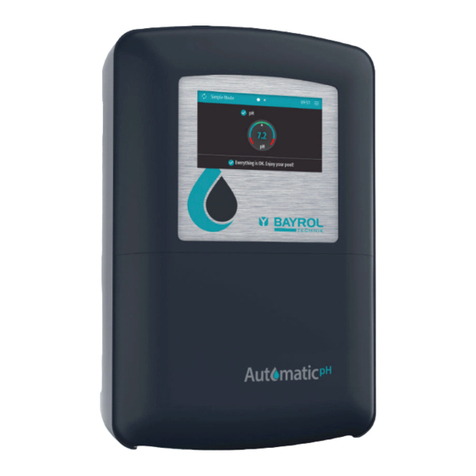
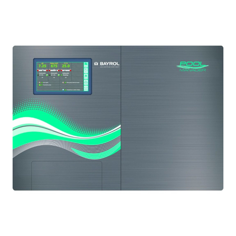
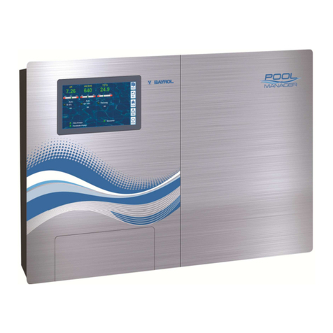
Bayrol Pool Relax Chlorine User manual

Pool Relax Instruction Manual, V1.0
Page 1 of 44
Pool Relax
Instruction Manual
Chlorine
Bromine
Oxygen

Pool Relax Instruction Manual, V1.0
Page 2 of 44
Contents
1INTRODUCTION ........................................................................................................................................5
2INSTALLATION OF POOL RELAX ...........................................................................................................6
2.1 General Information.................................................................................................................................6
2.2 Selecting the Installation Location.........................................................................................................6
2.3 Mounting Pool Relax on the Wall ...........................................................................................................6
2.4 Electrical Connection...............................................................................................................................7
2.4.1 Double Dosing Pump Lock ..................................................................................................................7
2.4.2 Earthing the Measurement Cell ...........................................................................................................7
2.5 Installation Plans......................................................................................................................................8
2.5.1 Pool RelaxChlorine Connection..........................................................................................................8
2.5.2 Pool RelaxOxygen connection............................................................................................................8
2.5.3 Pool RelaxBromine connection...........................................................................................................9
2.6 Putting into Operation .............................................................................................................................9
2.6.1 Pool RelaxChlorine.............................................................................................................................9
2.6.2 Pool RelaxOxygen............................................................................................................................10
2.6.3 Pool RelaxBromine...........................................................................................................................11
3MAINTENANCE OF POOL RELAX .........................................................................................................12
3.1 Maintenance Plan...................................................................................................................................12
3.2 Dosing Pump Hoses ..............................................................................................................................12
3.3 Electrode Information............................................................................................................................13
3.3.1 Electrode Wear..................................................................................................................................13
3.3.2 Electrode Care...................................................................................................................................13
3.3.3 Calibrating Electrodes........................................................................................................................13
3.4 Decommissioning / Winter Storage of the System.............................................................................13
4OPERATING POOL RELAX ....................................................................................................................14
4.1 Overviewof Features.............................................................................................................................14
4.1.1 Displayand Operation........................................................................................................................14
4.1.2 Measuring and Control.......................................................................................................................14
4.1.3 SafetyFunctions ................................................................................................................................14
4.2 Operating principles ..............................................................................................................................15
4.2.1 Keys ...................................................................................................................................................15
4.2.2 Cursor................................................................................................................................................15
4.2.3 Scrolling.............................................................................................................................................15
4.2.4 Making Entries...................................................................................................................................15
4.2.5 Additional Operating Functions..........................................................................................................16
4.3 Menu Structure.......................................................................................................................................16
5GENERAL FUNCTIONS...........................................................................................................................18
5.1 EntryCode Number................................................................................................................................18
5.2 Customer Level ......................................................................................................................................18
5.2.1 Configuration Menus..........................................................................................................................18
5.2.2 Global Configuration..........................................................................................................................19
5.2.3 Device Type Configuration.................................................................................................................20
5.2.4 PoolConnect Configuration................................................................................................................20
5.2.5 Event Log...........................................................................................................................................21
5.3 Info Page and Operating Notes.............................................................................................................21
5.4 Factory Level..........................................................................................................................................21
6ALARMS...................................................................................................................................................22
6.1 Overview .................................................................................................................................................22
6.2 Alarm Status ...........................................................................................................................................22

Pool Relax Instruction Manual, V1.0
Page 3 of 44
6.3 Signalling................................................................................................................................................23
6.3.1 Flashing Headlines ............................................................................................................................23
6.3.2 Automatic Activation ofthe Alarm Page.............................................................................................23
6.3.3 AlarmPage........................................................................................................................................23
6.3.4 AcousticAlarm Signal........................................................................................................................23
6.3.5 Blocking of Dosing.............................................................................................................................23
6.3.6 Potential-free AlarmRelay.................................................................................................................23
7PH MEASURING AND CONTROL MODULE..........................................................................................24
7.1 pH OverviewPage..................................................................................................................................24
7.2 pH Configuration....................................................................................................................................25
7.3 pH Calibration.........................................................................................................................................27
7.3.1 1-Point Calibration pH........................................................................................................................27
7.3.2 2-Point Calibration..............................................................................................................................28
7.3.3 Manual Setup of the Calibration Parameters.....................................................................................30
8REDOX MEASURING AND CONTROL MODULE (MV) .........................................................................31
8.1 Redox OverviewPage (mV)...................................................................................................................31
8.2 Redox (mV) Configuration.....................................................................................................................32
8.3 Redox (mV) Calibration .........................................................................................................................33
8.3.1 1-Point Calibration..............................................................................................................................33
9TEMPERATURE MEASUREMENT .........................................................................................................34
9.1 Temperature OverviewPage.................................................................................................................34
9.2 Temperature Configuration...................................................................................................................34
9.3 1-PointCalibration Temperature ..........................................................................................................35
10 O2AUTOMATIC DOSINGSYSTEM ........................................................................................................36
10.1 O2 OverviewPage...................................................................................................................................36
10.2 O2 Configuration.....................................................................................................................................37
11 DETAILED DESCRIPTION OF FUNCTIONS ..........................................................................................38
11.1 Control (pH, mV).....................................................................................................................................38
11.1.1 Proportional Range........................................................................................................................38
11.1.2 Calculating the Dosing Rate..........................................................................................................38
11.2 O2 Automatic Dosing System................................................................................................................39
11.2.1 O2 AutomaticDosing Without Temperature Compensation..........................................................39
11.2.2 O2 AutomaticDosing with Temperature Compensation................................................................39
12 ELECTRICAL CONNECTIONS................................................................................................................41
12.1 Connections on the Controller Housing..............................................................................................41
12.2 Connections in the Controller Housing...............................................................................................42
13 SERVICE ..................................................................................................................................................43
13.1 Controller Board.....................................................................................................................................43
13.1.1 Exchange ofEPROMs (Software Update) ....................................................................................43
13.1.2 Changing the Buffer Battery..........................................................................................................43
13.1.3 Changing the Fuse........................................................................................................................43
13.1.4 PoolConnect Slot...........................................................................................................................43
13.2 Calibration Examples.............................................................................................................................44
13.2.1 1-Point Calibration (pH )...............................................................................................................44
13.2.2 2-Point Calibration pH....................................................................................................................44
13.2.3 1-Point Calibration forRedoxElectrode........................................................................................44

Pool Relax Instruction Manual, V1.0
Page 4 of 44
DANGER WARNINGS
Note: The dosing fluidsused are corrosive and / or inflammable. Neverallowthe two endsofthe pressure
hoses on vacuumpumps to hang loose, asthiswill permit the corrosive and inflammable fluids to escape.
During installation and operation, alwaysobserve the relevant health and safetyregulationswhen installing and
using the device. The systemshould onlybe installed and put into operation byqualified expert personnel.
WARNING
Changing the systemsettings (default values) can be dangerousundercertain circumstances. Therefore,
changesmust onlybe made bytrained technicians. The operatorassumes liabilityif the equipment is used
improperlyorthe settingsare modified incorrectly.
The systemmust be switched offimmediatelyand protected against being switched on again if it probable that
the systemcannot be operated safely and without danger.
This is the case, for example, if
•the systemisvisiblydamaged,
•the systemno longer appears to be functional forwhatever reason,
•the systemwas stored forlengthyperiodsunderunfavourable conditions(e.g. improper winter storage)
List of Abbreviations
pH pH value [pH], also abbreviation for pH control
mV Redoxpotential [mV], also abbreviation for redox control or measurement
T Temperature [°C/°F], also abbreviation of temperature measurement
D+ Dosage to raise pH / mV measurement
D- Dosage to lower pH / mV measurement
A/D converter Analogue/digital converter
LCD Liquid crystal display
LED Light emitting diode
Warning for preventing potential problems.

Pool Relax Instruction Manual, V1.0
Page 5 of 44
1 Introduction
Congratulationson the purchase of your Pool Relaxmeasuring, controlling and dosing system. You have
decided for a device that greatlysimplifies the care of your swimming pool with itshigh qualitydesign and
operating reliability.
Regardless ofwhich treatment method you have decided to use, your newPool Relax will manage the water
qualityin your pool.
Pool Relaxisavailable as
Pool Relax Chlorine
For measuring and controlling pH and redoxvalues, dosing ofpH-Minus or pH-Plus (adjustable) and
ChloriLiquid.
Pool Relax Bromine
For measuring and controlling pH and redoxvalues, dosing ofpH-Minus or pH-Plus (adjustable). Bromine, a
waterdisinfection agent, is dissolved in a feeder and added asneeded viaa dosing valve.
Pool Relax Oxygen
For measuring and controlling pH and redoxvalues, dosing ofpH-Minus or pH-Plus (adjustable), and time-
controlled and temperature-compensated dosing ofBayroSoft.
To obtain crystal clear water, Flockmatic can be used asan option with all three treatment variants. By
continuouslyadding the flocculant, the systemeven removesparticlesfromthe swimming pool water that
would otherwise simplypassthrough the sand filter ofyoursystem.
Ifyou would like to have accessto your Pool Relax systemfromanywhere, we recommend the use of
PoolConnect. With this GSMmodule, you can communicate with your systemvia SMSat anytime. For
example, you can call up the water values orhave the systemsend anyalarms to yourmobilephone.
Please read these instructions carefullyto familiarize yourself with the systemand how to operate it. If you
have anyquestions, please contact your dealer or the BAYROL Service Centre.

Pool Relax Instruction Manual, V1.0
Page 6 of 44
2 Installationof Pool Relax
2.1 General Information
Performallinstallation workcarefullyand complywith the applicable safetyregulations. During installation,
disconnect the measurement, control and dosing device and allotherelectrical loads such asthe electrical
heating orthe circulating pump fromthe mains.
In addition, complywith the applicable regulationsregarding the installation of electricaldevices.
General notes on installation:
•Ensure that the hoses are laid without kinking and that chafing cannot occur.
•Avoid laying the hoses over sharp edges.
•Carefully connect all hoses and check that the connections are firmlyattached.
•Avoid unnecessarilylong hose lengths.
•Do not guide the hosesdirectlyoverwarmpipesorsystems.
•Checkthat the float in the measurement chamber can float freely.
•Adjust the water flow through the cellso that the float just barely lies against the upperend in its guide
bore.
•Ifyou are using a Flockmaticpump fordosing Quickflock Automatic+, please connect it to a
connection controlled bythe circulating pump(circulation OFF – flocculation OFF; circulation ON –
flocculation ON)
2.2 Selecting the Installation Location
To mount Pool Relax, select a dry, frost-protected, sheltered and level location on a vertical wall. Ensure that
the area is readilyaccessible and well-ventilated. There should be no energized electrical cables, contactors,
electricmotors, etc. in itsvicinity. The installation location should be as close aspossible to where the
measuring waterisextracted and returned.
The supplyvoltage forthe controllerand the vacuumpumps should not exceed 240V/50Hz. The allowable
operating temperature range isfrom0 to 50OC, and the allowable humiditylevel equals 0-90 %.
Ifyou are using a PoolConnect system, the installation location selected should havea good network
connection. Ifthisisnot possible, the antenna can be replaced bya more sensitive antenna or connected to
Pool Relaxusing a high qualityextension cable (both ofwhich are commerciallyavailable).
2.3 Mounting Pool Relax onthe Wall
•The base plate with the mounted measurement cell can be used as a template byholding it up against the
mounting location and marking the drill holes on the wall.
•After the base plate is securelymounted on the wall, the controller housing isattached to the tongue and
groove joint provided for this purpose.
•The housing is attached using a slotted screw that can be accessed through an opening in the pump hood
holder.

Pool Relax Instruction Manual, V1.0
Page 7 of 44
•Connect the supplied pH pressure line on one side with the pressure side (right connector)ofthe left-hand
vacuumpump. Connect the other side with the upper
injection piece ofthe measurement cell. Ensure that the connection is tight and securelyfastened.
•Connect the supplied pressure line forChloriLiquid or BayroSoft on one side with the pressure side ofthe
right-hand vacuumpump. Connect the other side with the upper
injection piece ofthe measurement cell. Ensure that the connection is tight and securelyfastened.
•Connect the flow switch and the temperature sensor(Pool RelaxOxygen only). Ensure that the connectors
are inserted in the sockets provided forthispurpose (see the "Stickerson Controller Housing" and
"Connections on Controller Housing" chapters).
2.4 Electrical Connection
The systemhas been designed and constructed according to theapplicable regulations. It wascarefully
inspected before leaving the factoryand left the factoryin a perfectlysafe condition.
The equipment can onlybe operated safelyifall ofthe instructionscontained in thismanual are followed. The
equipment should be installed bya licensed electrician.
The supplyvoltage forthe device maynot exceed 240 V / 50 Hz. The allowable operating temperature range is
from0 to 50OC, and the allowable humiditylevel equals 0-90 %.
Ensure that all plug-in connectionsare protected against water, as is standard practice for electrical
connections.
2.4.1 Double Dosing Pump Lock
Pool Relaxisequipped with a double pump lock that offers a veryhigh levelofsafety.
The flow switch in the measurement cell ensures that the dosing pumpscan onlybe switched on ifa sufficient
amount of water isflowing through the measurement cell.
In addition, the dosing pumpsare supplied with the line voltage through a separate power supply. The power
supplymust be switched in such a manner that the dosing pumps are onlysupplied with current when the
circulating pump is running.
In this way, dangerous dosing is prevented even in situationsin which there isno flow, i.e. the systemis doubly
safeguarded.
For connections, please see the "Connections on Controller Housing" chapter.
2.4.2 Earthing the Measurement Cell
The Pool Relaxmeasurement cell isequipped with an earth screw that is used fordiverting anypotentialson
the pool water.
Note: The earthing provided forthe plexiglass measurement chamber MUSTbe
installed. Thisearthing SHOULD NOTbe laid into Pool Relax(earthing via the Pool
Relax power cable)but MUSTbe connected to a separate, secure earth. Make sure that
the earthing isfunctioning properly.
Alwaysensure that fault current isnot flowing into the water ofthe swimming pool.
Professional measurement isrecommended.

Pool Relax Instruction Manual, V1.0
Page 8 of 44
2.5 Installation Plans
2.5.1 Pool Relax Chlorine Connection
2.5.2 Pool Relax Oxygen connection
1 Pool Relax Chlorine
2 Measurement water
intake
3 Measurement water
return
4 Swimming pool
5 Circulating pump
6 Sand filter
7 Heat exchanger
8 pH pressure line
9 ChloriLiquid pressure line
10 Containers for pH-Minus
and ChloriLiquid
11 pH-Minussuction line
12 ChloriLiquid suction line
13 Flockmatic (optional)
14 Quickflock Automatic+
canister(optional)
15 Prefilter
1 Pool Relax Oxygen
2 Measurement water
intake
3 Measurement water
return
4 Swimming pool
5 Circulating pump
6 Sand filter
7 Heat exchanger
8 pH pressure line
9 BayroSoft pressure line
10 pH-Minusand BayroSoft
containers
11 pH-Minussuction line
12 BayroSoft suction line
13 Flockmatic (optional)
14 Quickflock Automatic+
canister (optional)
15 Prefilter

Pool Relax Instruction Manual, V1.0
Page 9 of 44
2.5.3 Pool Relax Bromine connection
2.6 Putting intoOperation
Before putting the systeminto operation, all previouslydescribed steps must be performed and the conditions
specified there must be met!
In addition, the containerswith the water care agents must be connected to the system.
•To do so, connect the hose ofthe dosing lanceswith the suction side (left connector) of the respective
dosing pump. Ensure that the hose lengthsare short and that the screw connectionson the pump and
suction lance are firmlyattached.
•Connect the BNC connectors ofthe suction lances with the respective socket on the controller (see also the
"Connection on Controller Housing" chapter).
ATTENTION: Use BAYROL watercare products only!
2.6.1 Pool Relax Chlorine
•Bring the pH value of the pool waterto 7.2. You can manuallydose the pH to do so(see "pH Measuring and
Control Module"). Ifthe pH value differswidelyfrom7.2, you can use pH-Minus/pH-Plusin a granularform
(it is important that you followthe dosing instructions on the product package). It isimportant that you check
the pH value with the supplied pool tester.
•After adjusting the pH value, bring the chlorine value ofthe swimming pool waterto the desired level of free
chlorine (recommendation: 0.6 mg/l). You can manuallydose the Cl to do so (see "Redox Measuring and
Control Module"). In large pools, you can also use Chlorifix(follow the dosing instructionson the product
packaging). It isimportant that you check the chlorine value with the supplied pool tester.
•When you adjust the pH and chlorine value of the pool water, you can simultaneouslycalibrate the pH and
redox electrodeswith the buffer solution provided. Applythe 1-point calibration method for both electrodes.
•The redox value that results when the chlorine value of the pool waterisadjusted (recommendation:
0.6 mg/l) can be used asthe redoxsetpoint. A precondition isthat the pH value must alreadybe close to the
setpoint (+/- 0.1) and the redox electrode must be calibrated with the redox buffer.
1 Pool Relax Bromine
2 Measurement water
intake
3 Measurement water
return
4 Swimming pool
5 Circulating pump
6 Sand filter
7 Heat exchanger
8 pH pressure line
9 pH pressure line
10 pH-Minuscontainer
11 pH-Minussuction line
12 Bromine feeder
13 Flockmatic (optional)
14 Quickflock Automatic+
canister (optional)
15 Prefilter
16 Bromine magnetic valve

Pool Relax Instruction Manual, V1.0
Page 10 of 44
•Assoon asthe pH and redox valuesin the poolwater are close to the setpoints, you can set the control of
the two control modules to Auto.
•We recommend that you monitor the control behaviour over a period of time and adjust it to the conditions
prevailing in the pool, ifnecessary. In particular, thisapplieswhen the current values in the pool still vary
widelyfromthe setpoints.
APoolConnect module can be used for thispurpose, which enables access to PoolRelax via a mobile
phone.
2.6.2 Pool Relax Oxygen
To ensure good water qualitywhen treating water with BayroSoft, carefullyadhere to the following
requirements.
A) Technicalrequirements
•Correct installation and operation of the pool’s hydraulic equipment, water supply(including overflow tank)
and filtering system
•The filter must operate for at least 10 hours/day
•Backwash at least once a week
•Sufficientlyhigh backwash speed of60 m/h and backwash time of at least 3 minutes
•Walls and floor ofthe pool must be cleaned regularlyusing a suction device– pool vacuumcleaner
•Filtersand must be checked regularlyand replaced as necessary
B) Measures required inaddition to dosing withBayroSoft
•Before putting the systeminto operation, administer a shock chlorination using 25 g ofChlorifix percubic
metre of water. The chlorine should act for at least 3 days.
•Alined swimming pool with a newlinermust be treated with chlorine for at least 14 days during which the
chlorine level must be kept constant at over 3 mg/l.
•After thisperiod, start the BayroSoft treatment immediatelyand do not wait for the chlorine level to break
down.
•Regular flocculation with Superflockor the Flockmatic dosing device
(QuickflockAutomatic+)ishighlyrecommended.
•Occasionallycheck that BayroSoft is present in the water. Ifpossible, do thison the daypreceding the next
dosing (there should still be at least 10 mg/l of BayroSoft in the pool).
To check this, simplydip a BayroSoft QuickTest test strip into the water. A blue discolouration indicatesthat
BayroSoft ispresent.
C) Tips and tricks regarding inadequate water quality(BayroSoft)
Generallyspeaking, inadequate water qualityiscaused bya lackofBayroSoft in the swimming pool’s water
over a long period of time. Organic substancescan build up in the water, resulting in cloudinessor causing the
swimming pool walls to become slippery.When this first occurs, checkto see whetherthere isanyBayroSoft in
the water. Dip a BayroSoft test strip in the watershortly before the next dosing takesplace. The test strip must
at least turn light blue (correspondsto approx. 10 mg/l). If no traceof BayroSoft can be detected, increase the
dose amount so that BayroSoft is always present in the water.
D) Howcan the water qualitybe corrected?
•Ifthe problemis just that the water is cloudybut the pool walls are not slippery, a double manualdosage
and the addition ofa Superflockflocculation cartridge will be sufficient. The water qualitywill be correct by
the next day.
•Ifthe water is cloudyand the pool walls are slippery, thisindicatessevere organiccontamination and it will
be necessaryto administer a single shock chlorination in order to return the water to the required quality.
Note: BayroSoft and chlorine neutralise each other, therebyrendering each other ineffective. Therefore, it
must be ensured that no BayroSoft remainsin the waterbefore applying chlorine. Otherwise the chlorine will
be ineffective. Use the BayroSoft test strips. An effective shock chlorination is only possible after there isno
blue discolouration, indicating that there is no more BayroSoft in the water.
Recommended dose amount for an effective chlorine shock: 1 tablet of Chloriklar per cubic metre or 25
gramsofChlorifixper cubic metre.

Pool Relax Instruction Manual, V1.0
Page 11 of 44
Important: When administering a shockchlorination, it isessential to clean the pool bymechanical
meansin addition. Slipperydeposits forma so-called "bio-film", which isnot be completelyeliminated even with
high concentrationsofchlorine. Assoon asthe slipperydeposit isdestroyed bymechanicalcleaning, the
chlorine can act and fullybreakdown the organiccontaminants. Resume BayroSoft water treatment at least
24 hours but no later than 48 hours after the chlorine shock is administered. You do not need to wait for the
chlorine levels to breakdown.
Procedure for Putting intoOperation
•Bring the pH value of the pool waterto 7.2. You can manuallydose the pH to do so (see "pH measuring and
control module"). Ifthe pH value differswidelyfrom7.2, you can use pH-Minus/pH-Plusin a granularform
(it is important that you followthe dosing instructions on the productpackage). Check the pH value with the
supplied Pooltester/BayroSoft test strips.
•Performthe shockchlorination specified under B).
•Determine the basic dose according to the formula
and enterthis value into the device as the basicdose.
•When you adjust the pH value or performa shock chlorination, you can simultaneouslycalibrate the pH
electrode with the supplied buffersolution. Apply the 1-point calibration method.
•Assoon asthe pH value isclose to the setpoints, you can set the control of thepH value and the O2
automaticdosing systemto Auto. At high water temperatures, also activate the temperature compensation
(see "Configuration O2" and "Functional Description O2").
•We recommend that you monitor the control behaviour over a period of time and adjust it to the conditions
prevailing in the pool, ifnecessary.
APoolConnect module can be used for thispurpose, which enables access to PoolRelax via a mobile
phone.
•In anycase, it is necessarythat you checkthe BayroSoft content in the pool water using the supplied
BayroSoft test strips. Shortly after the main dosing, the measured value should equal 35-50 mg/l (darkblue
colour) and shortly before the next main dosing the value should equal at least 10 mg/l (light blue colour).
2.6.3 Pool Relax Bromine
•Bring the pH value of the pool waterto 7.2. You can manuallydose the pH to do so (see "pH measuring and
control module"). Ifthe pH value differswidelyfrom7.2, you can use pH-Minus/pH-Plusin a granularform
(it is important that you followthe dosing instructions on the product package). It isimportant that you check
the pH value with the supplied pool tester.
•First bring the bromine value ofthe swimming pool waterto the desired value. (Recommendation: 2-4 mg/l).
ATTENTION: Depending on the poolsize and water temperature, this bromine value maynot reach its final
leveluntil afterseveral days. To ensure a sufficient degree of water disinfection fromthe beginning, we
recommend an initial disinfection with chlorine, e.g. with Chlorifix. It isimportant that you checkthe bromine
value with the supplied pool tester.
•When you adjust the pH and bromine value of the poolwater, you can simultaneouslycalibrate the pH and
redox electrodeswith the supplied buffer solution. Applythe 1-point calibration method forboth electrodes.
•The redox value that results when the bromine value of the poolwater isadjusted (recommendation:
2-4 mg/l) can be used asthe redoxsetpoint. A precondition is that the pH value must alreadybe close to
the setpoint (+/- 0.1)and the redoxelectrode must be calibrated with the redoxbuffer.
•Assoon asthe pH and redox valuesin the poolwater are close to the setpoints, you can set the control of
the two control modules to Auto.
•We recommend that you monitor the control behaviour over a period of time and adjust it to the conditions
prevailing in the pool, ifnecessary. In particular, thisapplieswhen the current values in the pool still vary
widelyfromthe setpoints.
APoolConnect module can be used for thispurpose, which enables access to PoolRelax via a mobile
phone.

Pool Relax Instruction Manual, V1.0
Page 12 of 44
3 Maintenance of Pool Relax
ATTENTION: Disconnect all powerconnectionsbefore beginning maintenance work!
3.1 Maintenance Plan
Monthlymaintenance:
•Visuallyinspect all dosing linesand hoses for leakages
•Check the filter sieve and clean it ifnecessary
•Check the watervalueswith the supplied test kitand readjust the settingsifnecessary
Quarterlymaintenance:
•Visuallyinspect all dosing linesand hoses for leakages
•Check the filter sieve and clean it ifnecessary
•Check the watervalueswith the supplied test kitand readjust the settingsifnecessary
•Calibrate the pH and redox electrodesusing the supplied buffer solutions
Annual maintenance:
•Visuallyinspect all dosing linesand hoses for leakages
•Check the filter sieve and clean it ifnecessary
•Check the watervalueswith the supplied test kitand readjust the settingsifnecessary
•Replace and calibrate the pH and redox electrodesusing the supplied buffer solutions
•Replace the hoses ofthe dosing pumps
3.2 Dosing Pump Hoses
The hoses ofthe dosing pumps must be replaced annuallyor earlierifworn. Use original replacement hoses
only. Theycan be obtained fromyourswimming pooldealer.
The following hosesmaybe used:
171 219 Replacement hose set 0.9 l/h (for chlorine and pH-Plus/pH-Minus, recognizable bythe white nozzles)
171 216 Replacement hose set 6.0 l/h (forBayroSoft, recognizable bythe blacknozzles)
Hose Replacement
To replace the hoses, proceed asfollows:
•Rinse the pump with fresh, lukewarmwater for about 30 minutes. To do so, place the suction lances into a
pail filled with tap water and start a manual dosing.
•Ensure that the systemisfullydisconnected fromthe power grid. This preventsthe pump fromswitching on
during the maintenance procedure.
•Lift the blue coversfromthe pumpsand remove the suction and pressure hoses.
•Pressthe band together at the recessed gripsand turn the catch clockwise all the way.
•Move both hose ends outward and remove the band with the hose.
•Pull the old hose out ofthe two guidesand insert the new hose.
•To mount the hose band and hose, proceed in reverse order. Ensure that the hose is firmlyseated in the
guidesand that the catch hasengaged.
•Assoon asall connectionshave been closed, you can purgethe air fromthe dosing hose. To do so,
connect Pool Relaxwith the mainsand start a manual dosing.

Pool Relax Instruction Manual, V1.0
Page 13 of 44
Figure: Top of the pump
3.3 Electrode Information
The electrodesmust be replaced annuallyor earlier if worn. Use original replacement electrodes only. They
can be obtained fromyour swimming pooldealer.
3.3.1 Electrode Wear
The following conditions, among others, indicate that the electrodes are worn:
•During calibration, the electrode takes unusuallylong to reach the value ofthe buffer solution.
•The electrode offset during calibration is too large.
•The KCL solution in the electrode shaft isused up or discoloured.
ATTENTION: Electrodes wearveryrapidlyif there is an electric potential in the pool water!
3.3.2 Electrode Care
•The pH-sensitive membrane glassmust be handled with care and protected against damage.
•The innerreference solution in the glass electrode must cover the innersurface of
the membrane glass. Anyair bubbles are removed bygently shaking the electrode vertically(like shaking a
medical thermometer).
Contamination deposited on the surface ofthe membrane glass must be removed bycarefullywiping it with a
moist papertowel. Alternatively, you can use the supplied electrode cleaning solution.
3.3.3 Calibrating Electrodes
Noteson calibrating electrodes can be found in the corresponding chapters and in the calibration examples.
3.4 Decommissioning / Winter Storage of the System
Ifthe systemis put out of operation for lengthyperiods, e.g. forwinter storage, certain precautionarymeasures
need to be taken. In particular, it isveryimportant that the entire systemisprotected against freezing
temperatures and humidity.
Dosing System
•Rinse the pump with fresh, lukewarmwater for about 30 minutes. To do so, place the suction lance into a
pail filled with tap water and start a manual dosing.
•Ensure that the systemisfullydisconnected fromthe power grid.
•Release the hose set to prevent permanent deformation.
Measuring System
•Store the electrodes in an upright position in the containers in a location where temperatureswill not drop
below zero. The three molarKCL solution in the containers protects the electrodesfromdrying out.
•Close both electrode drill holesof the measurement cell with the supplied cover screws.
•Let the water drain fromthe measurement chamberand measurement lines.

Pool Relax Instruction Manual, V1.0
Page 14 of 44
4 OperatingPool Relax
4.1 Overviewof Features
4.1.1 Displayand Operation
•4-line multifunctional LC display, bluemode (4 x 20 characters)
•Simple 6-keyoperation
•Clearmenu structure
•Menuscan be displayed in a varietyofselectable languages
4.1.2 Measuring and Control
•Proportional control for all control modules
•All important control parameterscan be programmed individuallyfor each control module (setpoint,
maximumdosing time, proportional range, dead zone (pH), basic dose (mV), minimumswitched-
on/switched-off time)
•Continuousdisplayof current dosing rate
•Conversion ofall measurements byhigh resolution 10-bit analogue/digital converters
•1- or 2-point calibration forpH measurements
•1-point calibration ofmV and Tmeasurements
4.1.3 SafetyFunctions
•Comprehensive monitoring and alarm functions
(upperand lowerthreshold alarms, flow alarm, level alarms, dosing time alarms, calibration time alarms,
batteryalarm, power-on delay, automatic blocking ofdosing during critical alarm conditions and during
power-on delay, alarmnotification through
Ødisplay
Øacoustic alarm signal
Øpotential-free relayfor external alarm outputs
•continuousmonitoring of the correct programsequence and automaticreset in the event ofan error
(watchdog function)
•Double dosing pump lock
Pool Relaxisequipped with a double pump lock that offers a veryhigh level ofsafety.
The flow switch in the measurement cell ensures that the dosing pumpscan onlybe switched on ifa
sufficient amount of waterisflowing through the measurement cell.
In addition, the dosing pumpsare supplied with the line voltage through a separate power supply. The
power supplymust be switched in such a manner that the dosing pumpsare onlysupplied with current
when the circulating pump isrunning.
In this way, dangerous dosing into stationarywater is prevented even ifone ofthe two fusesshould blow
due to external causes.
•Alternating switching on ofthe dosing pumps
Assoon asa dosing pump starts running, the other pump is blocked. This preventsthe agents for raising or
lowering the pH frombeing dosed togetherwith the waterdisinfection agent (ChloriLiquid orBayroSoft).
Because perfect water disinfection isonlypossible at a pH value of7.2, dosing of the agentsforraising and
lowering the pH takesprecedence over dosing ofthe water disinfection agent.
ATTENTION: pH-Minus and ChloriLiquid should never come into contact with each
other – Danger of chlorine gas!

Pool Relax Instruction Manual, V1.0
Page 15 of 44
4.2 Operating principles
4.2.1 Keys
Pool Relax isoperated entirelyon 6 keys. Theyare integrated in the front membrane of the device.
4.2.2 Cursor
Certain elementswithin the displaypages can be selected using a cursor (underscore) that can be moved
using the , , and keys.
The cursoralso indicates whether the device is in NormalMode or in EntryMode. EntryMode is indicated by
flashing ofthe cursor. In EntryMode, the parameter currentlyselected can be adjusted.
4.2.3 Scrolling
Ifa displaypage consists ofmore than fourlines, you can scroll using the / keys.
4.2.4 Making Entries
The , , , keysare used to navigate on a displaypage.
The keyconfirms an entryand the keyis used to leave individual settingsand menu items/levels.
Entries are made in several consecutive steps that are described below.
1. Selecting the Elementto Be Entered
Using the / keys(line up / down) and / (left / right), the cursor is first positioned on
the element to be adjusted.
2. Activating the EntryMode
EntryMode is activated bypressing the key. EntryMode isindicated byflashing ofthe cursor.
3. Entry
In EntryMode, the selected setting can be changed using the and keys. To enter multiple
digits, the digits can be selected using the and keys.
Cursor
Illustration of
Pool Relax Chlorine

Pool Relax Instruction Manual, V1.0
Page 16 of 44
4. Quitting EntryMode
EntryMode is quit bypressing the keyagain. The cursor stops flashing and the newlyset value is
adopted.
4.2.5 Additional Operating Functions
•Acknowledge an active alarmon the alarmpage with .
•Change to a lower menu level (e.g. fromthe CustomerLevel menu) byselecting the desired submenu
using / and confirm with .
•Change froma lower menu level (Customer or FactoryLevel)to the next highest level using .
4.3 Menu Structure
The Pool Relaxmenu structure isrestricted to three levelsto permit a rapid and intuitive navigation through the
levels.
•Main Menu Level
ØDisplayofall current measuring and control parameters
ØSwitching the operating mode ofthe individual modules
ØDisplayofall current alarms
ØAcknowledging ofalarms
ØEntryofcode numbers to open the Customer or FactoryLevel
•Customer Level
Pool Relaxsupports two different operating modes at the CustomerLevel. In the User Mode (password:
123), onlythe most important setting parametersare available.
In the Service Mode (password: 456), all parameters are available.
ØConfiguration of all measuring and control parameters
ØCalibration of measurement value collection
ØDisplayofevent log
The password entryfor the CustomerLevel can be deactivated at the FactoryLevel. In addition, the
passwords can be changed there.
•FactoryLevel – (password: 1111)
Configuration ofseveral device parameters, e.g. the code number ofthe Customer Level, in production
and in service.
In addition, a page isavailable containing information such as the device type, the software version and
operating notes. It can be activated fromanyother page at anytime bya double clickleft/right.
NOTE: The parameter settingsin the individual menusare the basisforthe correct and safe operation of the
system. Theyshould onlybe changed bytrained technicians.

Pool Relax Instruction Manual, V1.0
Page 17 of 44
Main Page
(Overview)
Alarm Page
(List of all alarms)
EntryCode
Config. pH
Manual Dos.
(Cal. Parameter)
(2-Point Cal.)
1-Point Cal.
Setpoint
L-Alarm
U-Alarm
Dosing Time
(p-Range)
(Dead Zone)
(Dosing Period)
(Min ESD)
(Control)
(Cal. Interv.)
Config. mV
Manual dosage
Setpoint
1-Point Cal.
L-Alarm
U-Alarm
(Dosing Time)
(Cal. Interv.)
(p-Range)
(Basic Dos.)
(Min ESD)
(Control)
Config. O2
Dosing Days
Dosing Amount
T-Comp.
T3/3
T2/3
T1/3
TWeek
(6s Dos.)
Config. T
1-Point Cal.
L-Alarm
U-Alarm
(Cal Interv.)
Global Config.
Day
Date
Time
Battery
Sound Alarm
Flow
Level
(Others)
(Flow Status)
(Language)
(Level Alarm)
(pH)
(Disinf.)
(Power-on Delay)
(Del.Flow Al. Delay)
(Confirm Flow Al.)
(Powerdown)
(Default Conf.)
Factory Level
Customer Code
No.
Serv. Code No.
Customer Level
Defaults
Level AlDos.
Dos. O2
Any
page
Info Page &
Operating Notes
Device Type
Software Version
Operating Notes
FactoryLevel: 1111
*Customer Level:
User Mode: 123
Service Mode: 456
Customer Level
Config. pH
Config. mV
Config. O2
Config. T
Config. Global
Config. Device Type
Config. PoolConnect
Event Log
Config. PoolConnect
Network?
Reception
Send Test SMS
Tel. No. 1
Tel. No. 2
Device Name
SMS PIN
Cycle Value
Cycle Alarms
Flow SMS
Flow Time
Error Message
SWVersion
Event Log
Saves all alarms and other
important events with the date and
time, including power failures.
*Remark:
All parameters printed in italics and set in brackets are onlyavailable in the
Service Mode at the CustomerLevel, not in the UserMode.
Config. Device Type
Cur. Pool Relax
NewPool Relax
Code No.
Abbreviations:
Acoust. = Acoustic
Al. = Alarm
Dos.= Dosing
Disinf. =Disinfection
ESD = Switched-on time
Interv. = Interval
Cal. = Calibration
Comp. = Compensation
Conf. & Config. = Configuration
Min = Minimum
No. = Number
Ackn. = Acknowledge
Serv. = Service
Tel. =Telephone
T & Temp. = Temperature
Del. = Delay
Overviewof Menu Structure

Pool Relax Instruction Manual, V1.0
Page 18 of 44
5 General Functions
This chapter describes generalfunctions that do not varywith the device type:
5.1 EntryCode Number
The setting parameters in the Customeror FactoryLevel can onlybe changed after the correct code number
hasbeen entered.
Entryofthe code numberforthe Customer Level can be fullydeactivated (FactoryLevel).
The Customer or FactoryLevel is activated after entering the correct code numberand confirming with .
5.2 CustomerLevel
Important:
•Pool Relaxoffers two operating modes at the Customer Level. In the User Mode, onlythe most important
setting parameters are available. Thiskeepsthe CustomerLevel compact and manageable. In the Service
Mode, the userhas access to all available parameters.
Depending on the code number entered, the customer level isactivated in the User Mode or in the Service
Mode. Ifdesired, entryofthe code number can be deactivated at the FactoryLevel.
•While the CustomerLevel is active, dosing isblocked for all modules.
After quitting the Customer Level, the device returnsto normal operation.
•Ifno keyispressed for 10 minutesat the CustomerLevel, the Customer Level isclosed automaticallyand
the device returns to normal operation. In thiscase, incomplete entriesare rejected.
5.2.1 Configuration Menus
After the CustomerLevel isactivated, a selection menu appears fromwhich you can navigate to the
configuration menusfor the modulescontained in the device type you have.
In addition, you can navigate to the global configuration,the device type configuration and the event log.

Pool Relax Instruction Manual, V1.0
Page 19 of 44
5.2.2 GlobalConfiguration
On the Global Configuration entrypage, you can set all operating parameters that are not associated with a
specificmodule (pH, mV, T) but that have a more global character.
Line Content Value range Default Unit Adjustable
1 Global config. Headline No
2 Day Monday/ Tuesday/ Wednesday/
Thursday/ Friday/ Saturday/
Sunday
- Yes
3 Date dd.mm.yyyy - Yes
4 Time hh:mm:ss - Yes
5 Battery 0.0 ... 3.5 - V No
6 Acoust. alarm Headline No
7 Flow Active / inactive Inactive Yes
8 Level Active / inactive Active Yes
9 Others Active / inactive Active Yes
10 Flowstatus On / off - No
11 Language German / English / Francais /
Italiano / Espanol / Russian /
Polski / Greek/ Menu
German Yes
12 Level alarm Headline No
13 pH Active / inactive Active Yes
14 Disinf. Active / inactive Active Yes
15 Power-on
delay 01 ... 30 05 Min Yes
16 Confirmflow
al. Auto / manual Auto Yes
17 Powerdown Active / inactive Active Yes
18 Default conf. OK - Yes
Day (line 2)
Setting ofthe current dayofthe week.
Date (line 3)
Setting ofthe current date in the format ofDay.Month.Year.
Time (line 4)
Setting ofthe current time in the format ofHours:Minutes:Seconds.
Battery(line 5)
Displayofthe current voltage ofthe internal 3Vbuffer batteryfor the real-time clock.
Ifthe batteryvoltage falls below2.8 V, Pool Relax triggers a BatteryAlarm. In thiscase, the battery
(CR 2032)must be replaced immediately.
Sound Alarm Flow(line 7)
Activation or deactivation ofthe sound alarmin the event of a FlowAlarm.
Sound Alarm Level (line 8)
Activation or deactivation ofthe sound alarmin the event of a Level Alarm.
Sound Alarm Others (line 9)
Activation or deactivation ofthe sound alarmin the event of other alarms.

Pool Relax Instruction Manual, V1.0
Page 20 of 44
FlowStatus (line 10)
Displayofthe current statusof the flow signal for testing and adjustment purposes(on / off).
Language (line 11)
Setting ofthe desired menu language. If the "Menu" setting isactivated, a language selection menu
appearsthe next time you switch on the device.
Level Alarm pH (line 13)
Activation or deactivation ofthe level alarmpH.
When the alarmis deactivated, the pH levelinput is not monitored. In this case, no acousticalarmisissued,
no matter what the "Sound Alarm" setting.
Level Alarm Disinf. (line 14)
Activation or deactivation ofthe disinfectant levelalarm(mV or O2, depending on the device type).
When the alarmis deactivated, the disinfectant level input isnot monitored. In thiscase, noacousticalarm
is issued, no matter what the "Sound Alarm" setting.
Power-on Delay(line 15)
When the controller and the circulating pump are switched on, dosing remainsblocked for all modules for a
certain time, permitting measurementsto stabilise and thus ensuring that the systemwill operate correctly.
Confirm FlowAlarm (line 16)
Here you can define how PoolRelax is to handle a Flow Alarm:
Manual
In the "Manual" setting, the FlowAlarmis treated as an errorstatus. The Flow Alarm is not cleared until
the Flow Signal reappears and the user acknowledges the FlowAlarmon the device.
Auto
In the "Auto" setting, the FlowAlarmis treated asa normal operating status. Forexample, thisisuseful
in applications in which the circulating pump isswitched off at regularintervals. The Flow Alarmis
cleared automaticallywhen the Flow Signalreappears.
Powerdown (line 17)
The Powerdown function can be activated or deactivated here: Ifno keyispressed for 15 minutes, the
screen illumination switchesoff(energy-saving mode).
DefaultConfiguration (line 18)
Here, all parameters can be reset to their default values. Thisdoesnot affect the Type of Device, Date and
Time.
5.2.3 Device Type Configuration
On the "Config. Device Type" entrypage, Pool Relaxcan be set toanothertreatment type ifdesired. You can
select between Pool Relax O2(oxygen), Cl (chlorine) and Br (bromine).
ATTENTION: Achange in the device type isa majorintervention in the entire pool
treatment systemand mayonly be performed byexperienced experts!
Additional information on changing the configuration ofthe device type can be found in the manuals on the
optionallyavailable changeoversets.
5.2.4 PoolConnect Configuration
PoolConnect can be used with Pool Relax asan option. It enables the useful communication ofPool Relaxwith
up to two mobile phones.
Details on installing and configuring PoolConnect can be found in the documentation on the device or on the
BAYROL homepage.
Other manuals for Pool Relax Chlorine
1
This manual suits for next models
2
Table of contents
Other Bayrol Lighting Equipment manuals
Popular Lighting Equipment manuals by other brands
Lites
Lites PROFILE LED WHITE Owner's and service manual

Hama
Hama SpotLight Steady 120 II operating instructions

Biotop Garden
Biotop Garden D0420 user manual

Model Train Technology
Model Train Technology CABOOSE II Series Operation manual
Harman
Harman Martin ERA 400 Performance CLD user manual
ProLights
ProLights LUMIPIX8H user manual
