Bayrol PM5-SA4 User manual

User Manual
for
PM5-SA4 Converter 4-20mA
Plug-in module with 4 current outputs 4-20mA
rder No.: 127 011
Status as at 02.04.2013
Compatible with
PoolManager
®
PoolManager
®
PR
Analyt

PM5-SA4 Converter 4-20mA – User Manual 2
1 Identification of safety information
Please refer to the information concerning the
identification of safety information in your PoolManager
or Analyt user manual.
2 General safety information
HAZARD!
Please follow the general safety information
in your PoolManager
or Analyt user m
anual
carefully.
3 User qualification
Please refer to the different user qualifications as defined
in your PoolManager
or Analyt user manual.
4 O er iew
The PM5-SA4 Converter 4-20mA is a plug-in module for
the BAYROL Measuring, Control und Dosing Systems
PoolManager
and Analyt of the 5th generation (from
2012). It provides 4 standard current outputs 4-20mA,
which can be used to transmit the current measurement
readings to external systems, e.g. Building Management
Systems (BMS), remote displays or data loggers.
5 Installation
This chapter describes the installation of the PM5-SA4
plug-in module inside the PoolManager
controller and
the cable connections.
Required user qualification:
ELECTRICAL SPECIALIST
Electrical connection may only be performed by
an ELECTRICAL SPECIALIST as defined in the
chapter User qualification of
your PoolManager
or Analyt user manual
.
5.1 Opening the casing
HAZARD DUE TO VOLTAGE!
Inside the controller you
may get in touch with
dangerous electrical voltages.
Potential consequence: Death or the gra est
degree of injury.
Disconnect the controller from mains power
supply before opening the casing and
, in
particular, the lid of the connection terminal box.
IMPORTANT NOTICE!
Open on the right
Never open the casing on the left side, as
damage may otherwise occur.
Always open on the right side!
1. Firmly press the hinge on the right side out and to
the right.
2. Remove the cover plate and unhook the hinge on the
bottom.
3. Swing the casing cover open to the left.
PM5-SA4 Converter 4-20mA – User Manual 3
4. Unbolt the four screws of the lid of the connection
terminal box and remove the lid. Take out the
aluminium rail afterwards.
5. To close the casing, reverse this procedure.
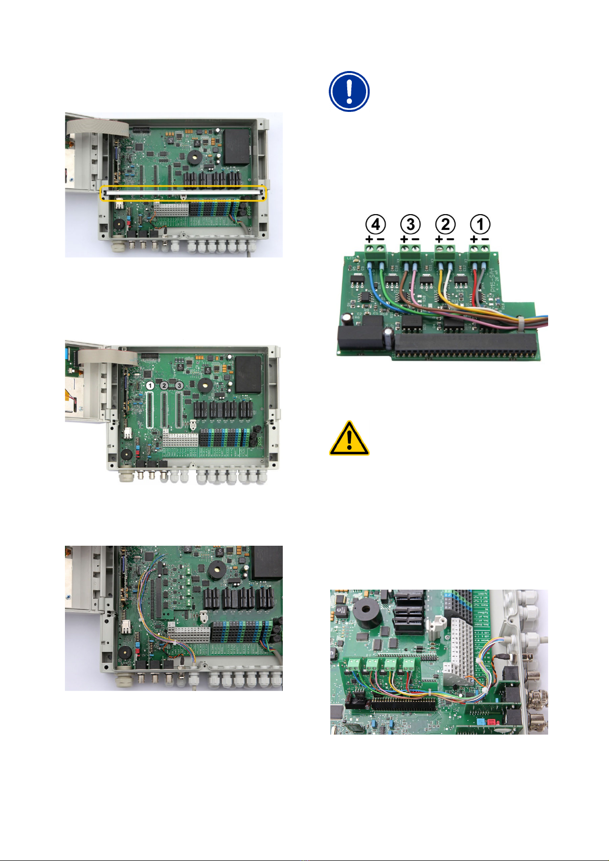
5.2 Insert the PM5-SA4 plug-in module
1. Use plug-in connector 1 (on the left) for the
installation of the PM5-SA4 plug-in module.
2. Dismantle the cable (or cables) on the required
length inside the casing and insert it (them) into the
casing through one or more cable glands.
IMPORTANT NOTICE!
In order to minimize the influence of possible
inductive disturbances,
we recommend to
use cables with twisted cable
pairs for each
channel.
3. Now connect the cable ends to the connection
terminals of the PM5-SA4 plug-in module. The digits
1 to 4 indicate the channel numbers which you can
later select in the configuration menu.
4. Insert the PM5-SA4 plug-in module carefully into the
plug-in connector 1 (on the left).
HAZARD!
Improper positioning
Improper (inaccurate) positioning of the plug-
in module and applying too strong forces
may bent or even break the contact
pins of
the plug-in connector.
Potential consequence:
Irreparable
damage
of the plug-in connector, need for
factory
repair ser ice.
Take care for the correct
and accurate
position of the plug-
in module and do not
apply too strong forces.

5.
Now insert the aluminium rail at its original position.
Take care that the PM5-SA4 plug
-
exactly located in the corresponding slot of the
aluminium rail as sh
own on the second photo below
6.
Remount the lid of the connection terminal box and
close the controller casing.
7.
After completion and verification of the installation
you can reconnect mains power supply to the
PoolManager
controller.
6 Technical data
Allowed ohmic resistance
of the connected current input
PM5-SA4 Converter 4-20mA – User Manual
Now insert the aluminium rail at its original position.
-
in module is
exactly located in the corresponding slot of the
own on the second photo below
.
Remount the lid of the connection terminal box and
After completion and verification of the installation
you can reconnect mains power supply to the
Min. Max.
0Ω 400Ω
7 Menu Confi
guration
The configuration menu for the
is called up as follows:
Menu Hotkey
Communication &
Interfaces
Submenu Current outputs
4
7.1
Output of measured alues
Select the submenu for the current output of the desired
measurement, e.g.
Current output
The following parameters can be set in this menu
Parameter
Possible
settings
Current output
pH / Cl / Br / mV /
O2 / T1
Current output
1.1 / 1.2 / 1.3 /
1.4
(1)
Minimum value
(at 4 mA)
Depends on measurement
Maximum value
(at 20 mA)
Depends on measurement
(1)
Current output x.y
means
- x is the No.
of the used plug
(usually this is plug-
in connector
- y is
the No. of the current output
on the PM5-SA4 plug-
in module
(2)
The default allocation is as follows
- Current output 1.1:
pH
- Current output 1.2:
Cl
- Current output 1.3:
mV
- Current output 1.4:
Temperatur
(3)
These Parameters
can be used to adjust the desired
measuring range which is output on the 4
current output.
The minimum
corresponds with the minimum
the maximum valu
e corresponds with
current signal of 20mA.
The default settings are as follows:
Minimum
. alue
(at 4
mA)
pH
0,00 pH
Cl or Br
0,00 mg/l
mV
0 mV
O2 0 l
T1 0°C
4
guration
The configuration menu for the
PM5-SA4 plug-in module
Interfaces
4
-20mA:
Output of measured alues
Select the submenu for the current output of the desired
Current output
pH.
The following parameters can be set in this menu
:
Possible
settings
Default setting
(default-set
Europe)
Current output
1.1 / 1.2 / 1.3 /
Depends on
measurement
(2)
Depends on measurement
(3)
Depends on measurement
(3)
means
:
of the used plug
-in connector
in connector
1)
the No. of the current output
in module
The default allocation is as follows
:
pH
Cl
or Br
mV
or O2
Temperatur
e T1
can be used to adjust the desired
measuring range which is output on the 4
-20 mA
The minimum
value always
corresponds with the minimum
current signal of 4 mA;
e corresponds with
the maximum
The default settings are as follows:
. alue
mA)
Maximum alue
(at 20 mA)
0,00 pH
10,00 pH
0,00 mg/l
10,00 mg/l
0 mV
1000 mV
10 l
50 °C
This manual suits for next models
1
Other Bayrol Media Converter manuals


