ASEA AC90SVHE-3 User manual

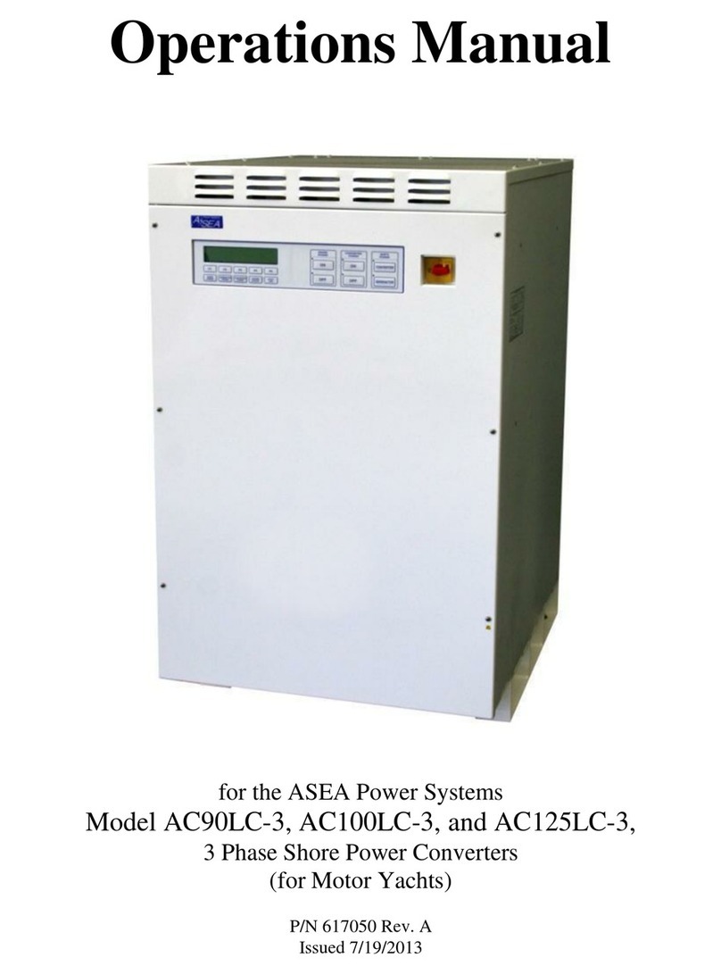
Operations Manual
for the ASEA Power Systems
Model AC90SVHE-3 and AC100SVHE-3
3 Phase Yacht Power Converters
P/N 605059
Revision ~
Issued 7/16/14

AC90SVHE-3 / AC100SVHE-3 Operations Manual....2
CERTIFICATION
ASEA Power Systems certifies that this product was thoroughly tested and inspected and found to meet or
exceed its published specifications when shipped from the factory.
WARRANTY
ASEA Power Systems warrants each unit to be free from defects in material and workmanship. For a
period of 18 months after purchase or 12 months after installation (whichever is shorter), ASEA Power
Systems will repair or replace any defective module provided the unit has been installed and operated in a
manner according to this manual. A thorough inventory of spare parts & modules is maintained at our
factory. Our world-wide sales/support facilities also inventory a complement of spare parts and modules.
ASEA Power Systems is not responsible for consequential damage arising from the use of its equipment.
It does not apply to extensively modified or non-standard systems. Debit memos for returned units are
not accepted, and will cause return of the system without repair.
LIFE SUPPORT POLICY
ASEA Power Systems does not authorize the use of any of its products or systems for use an AC voltage
supply (source) for life support systems. Life support systems are devices which support or sustain life,
and whose failure to perform, when properly used in accordance with this Operations Manual, can be
reasonably expected to result in significant injury to the user.

AC90SVHE-3 / AC100SVHE-3 Operations Manual....3
1 USING THIS MANUAL
This manual has been written as an Operations Manual. Installation, Operations, and
Preventative Maintenance are covered in detail. This manual will cover the following models:
AC90SVHE-3 90kVA 3 Phase Yacht Power Converter
AC100SVHE-3 100kVA 3 Phase Yacht Power Converter
Please note that these converters are capable of being paralleled for higher power applications.
The Model AC90SVHE-3 can be paralleled to produce the following models:
AC180SVHE-3/2 180kVA 3 Phase Yacht Power Converter
AC270SVHE-3/3 270kVA 3 Phase Yacht Power Converter
AC360SVHE-3/4 360kVA 3 Phase Yacht Power Converter
The Model AC100SVHE-3 can be paralleled to produce the following models:
AC200SVHE-3/2 200kVA 3 Phase Yacht Power Converter
AC300SVHE-3/3 300kVA 3 Phase Yacht Power Converter
AC400SVHE-3/4 400kVA 3 Phase Yacht Power Converter
It is important that the operator reads this manual prior to installing and operating the converter.
A thorough understanding of the information covered in this manual is required for proper
installation and operation.
If any questions arise while reading this manual, the user is encouraged to call ASEA Power
Systems. ASEA Power Systems is located at:
ASEA Power Systems
15602 Commerce Lane
Huntington Beach, CA. 92649
Phone (714) 896-9695
FAX (714) 896-9679
Web http://www.aseapower.com

AC90SVHE-3 / AC100SVHE-3 Operations Manual....4
TABLE OF CONTENTS
CERTIFICATION ...........................................................................................................................2
WARRANTY ..................................................................................................................................2
1 USING THIS MANUAL.....................................................................................................3
2 SAFETY NOTICES.............................................................................................................6
3 INTRODUCTION TO THE AC90SVHE-3 / AC100SVHE-3 ...........................................8
4 SPECIFICATIONS............................................................................................................10
4.1 ELECTRICAL SPECIFICATIONS ......................................................................10
4.1.1 Input Service..............................................................................................10
4.1.2 Output Service ...........................................................................................10
4.1.3 Control, Metering, and Status....................................................................11
4.1.4 Output Derating: Coolant Temperature.....................................................12
4.2 PHYSICAL SPECIFICATIONS ...........................................................................13
4.2.1 Mechanical.................................................................................................13
4.2.2 Environmental............................................................................................13
4.2.3 Coolant Requirements................................................................................13
5 INSTALLATION ..............................................................................................................14
5.1 MECHANICAL INSTALLATION.......................................................................15
5.1.1 General.......................................................................................................15
5.1.2 Clearances..................................................................................................15
5.1.3 Coolant Connections..................................................................................18
5.2 ELECTRICAL INSTALLATION.........................................................................19
5.2.1 Input Power Connections...........................................................................20
5.2.2 Output Power Connections........................................................................20
5.2.3 Grounding..................................................................................................22
5.2.4 Multi-Cabinet Connections........................................................................22
5.2.5 Seamless Transfer Connections.................................................................23
5.2.6 Other Option Connections .........................................................................24
6 OPERATION.....................................................................................................................25
6.1 POWER TURN-ON PROCEDURE......................................................................25
6.1.1 Systems Not Equipped With The Seamless Transfer Option....................27
6.1.2 Systems Equipped With The With Seamless Transfer Option..................28
6.2 MULTI-CABINET TURN-ON PROCEDURE ....................................................30
6.3 AUTO-RESTART FEATURE ..............................................................................31
6.3.1 Operation....................................................................................................32
6.4 TURN-OFF PROCEDURE...................................................................................33
6.4.1 Systems Not Equipped With The Seamless Transfer Option....................33
6.4.2 Systems Equipped With The Seamless Transfer Option...........................34
6.5 REMOTE COMMUNICATION...........................................................................35
6.5.1 RS-232C/SCPI...........................................................................................36
6.5.2 RS-485/Modbus.........................................................................................37

AC90SVHE-3 / AC100SVHE-3 Operations Manual....5
7 SOFTWARE FEATURES.................................................................................................39
7.1 GENERAL.............................................................................................................39
7.2 LOAD MANAGEMENT.......................................................................................39
7.3 LOAD MANAGEMENT OPERATION...............................................................41
7.3.1 Shore Cord Alarm, Single, Master, and Slave converters .........................41
7.3.2 Shore Cord Setup, Single, Master, or Slave Converters............................42
7.3.3 Voltage Droop, Single or Master Converters ............................................43
7.3.4 Automatic Transfer to Generator, Single or Master Converters (Seamless
Transfer installed)......................................................................................44
7.3.5 Quick Setup of Shore Cord Alarm, Single, Master, or Slave Converters..45
7.4 GENERATOR FREQUENCY ANALYSIS .........................................................46
7.5 CONVERTER OUTPUT IMPEDANCE CONTROL...........................................46
7.6 AGC CONTROL...................................................................................................47
7.7 kW-HOUR METER AND MAXIMUM POWER LEVEL DISPLAY.................48
7.8 CONVERTER OUTPUT VOLTAGE CONTROL...............................................49
7.9 EVENT LOG.........................................................................................................50
8 TROUBLE-SHOOTING AND DIAGNOSTICS..............................................................52
8.1 COMMON PROBLEMS.......................................................................................52
8.2 FAILURE AND WARNING MESSAGES...........................................................53
8.3 INFO DISPLAY ....................................................................................................53
8.4 STATUS WORDS.................................................................................................54
8.5 GATHERING DATA............................................................................................54
8.6 SOFTWARE TOOLS............................................................................................54
9 CALIBRATION ................................................................................................................56
10 MAINTENANCE..............................................................................................................58
11 INTERNATIONAL POWER FORM REFERENCE........................................................59
12 INDEX...............................................................................................................................64
FIGURES
1 SYSTEM BLOCK DIAGRAM...........................................................................................8
2 OUTPUT DERATING: COOLANT TEMPERATURE...................................................12
3 N/A.........................................................................................................................................
4 MECHANICAL OUTLINE AND CONTROLS...............................................................16
5 MECHANICAL OUTLINE...............................................................................................17
6 INPUT AND OUTPUT CONNECTIONS........................................................................21
7 FRONT PANEL CONTROLS ..........................................................................................25
8 RS-232C PINOUT.............................................................................................................36
9 RS-485 CONNECTIONS..................................................................................................37
10 STATUS WORD BIT DEFINITIONS..............................................................................55
This manual suits for next models
1
Table of contents
Other ASEA Media Converter manuals
Popular Media Converter manuals by other brands

H&B
H&B TX-100 Installation and instruction manual

Bolin Technology
Bolin Technology D Series user manual

IFM Electronic
IFM Electronic Efector 400 RN30 Series Device manual

GRASS VALLEY
GRASS VALLEY KUDOSPRO ULC2000 user manual

Linear Technology
Linear Technology DC1523A Demo Manual

Lika
Lika ROTAPULS I28 Series quick start guide

Weidmuller
Weidmuller IE-MC-VL Series Hardware installation guide

Optical Systems Design
Optical Systems Design OSD2139 Series Operator's manual

Tema Telecomunicazioni
Tema Telecomunicazioni AD615/S product manual

KTI Networks
KTI Networks KGC-352 Series installation guide

Gira
Gira 0588 Series operating instructions

Lika
Lika SFA-5000-FD user guide