CYP CSC-107 User manual

CSC-107
2×1 HDMI/VGA to HDMI Scaler
Operation Manual
Operation Manual


DISCLAIMERS
The information in this manual has been carefully checked and
is believed to be accurate. Cypress Technology assumes no
responsibility for any infringements of patents or other rights of third
parties which may result from its use.
Cypress Technology assumes no responsibility for any inaccuracies
that may be contained in this document. Cypress also makes no
commitment to update or to keep current the information contained
in this document.
Cypress Technology reserves the right to make improvements to this
document and/or product at any time and without notice.
COPYRIGHT NOTICE
No part of this document may be reproduced, transmitted,
transcribed, stored in a retrieval system, or any of its part translated
into any language or computer le, in any form or by any means—
electronic, mechanical, magnetic, optical, chemical, manual, or
otherwise—without express written permission and consent from
Cypress Technology.
© Copyright 2018 by Cypress Technology.
All Rights Reserved.
TRADEMARK ACKNOWLEDGMENTS
All products or service names mentioned in this document may be
trademarks of the companies with which they are associated.

SAFETY PRECAUTIONS
Please read all instructions before attempting to unpack, install or
operate this equipment and before connecting the power supply.
Please keep the following in mind as you unpack and install this
equipment:
• Always follow basic safety precautions to reduce the risk of re,
electrical shock and injury to persons.
• To prevent re or shock hazard, do not expose the unit to rain,
moisture or install this product near water.
• Never spill liquid of any kind on or into this product.
• Never push an object of any kind into this product through any
openings or empty slots in the unit, as you may damage parts
inside the unit.
• Do not attach the power supply cabling to building surfaces.
• Use only the supplied power supply unit (PSU). Do not use the PSU
if it is damaged.
• Do not allow anything to rest on the power cabling or allow any
weight to be placed upon it or any person walk on it.
• To protect the unit from overheating, do not block any vents or
openings in the unit housing that provide ventilation and allow for
sufcient space for air to circulate around the unit.
REVISION HISTORY
VERSION NO. DATE (DD/MM/YY) SUMMARY OF CHANGE
RDV1 2019/04/30 Preliminary release

CONTENTS
1. Introduction......................................................1
2. Applications.....................................................1
3. Package Contents ..........................................1
4. System Requirements......................................2
6. Operation Controls and Functions.................3
6.1 Front Panel ................................................. 3
6.2 Rear Panel.................................................. 4
6.3 RS-232 Pinout and Defaults ...................... 5
6.4 RS-232 Commands.................................... 5
7. Connection Diagram ....................................20
8. Specications ................................................21
8.1 Technical Specications ........................ 21
8.2 Video Specications............................... 22
8.3 Audio Specications ...................................24
8.3.1 Digital Audio................................... 24
8.3.2 Analog Audio ................................. 24
8.4 Cable Specications .............................. 25
9. Acronyms .......................................................26

1
1. INTRODUCTION
This compact, yet versatile, 4K UHD HDMI/VGA to HDMI Switching Scaler
accepts a wide range of resolutions from 480i up to 1080p/
WUXGA
over the VGA input and up to 4K@60Hz (4:4:4) on the HDMI input. With
the use of the 3.5mm audio input, stereo audio may be embedded
with either source as well. Scaled HDMI output resolutions are available
up to 4K@60Hz (4:4:4). Integrated EDID management options allow for
control over the way connected sources detect the unit. The included
automatic source detection and switching feature allows the unit to
switch automatically to the most recently connected source, or to
switch to the alternate input if the current one becomes disconnected.
The Auto Adjustment function, activated by a button on the unit, can
automatically adjust the image position of the VGA source if necessary.
This unit is an ideal device for integrating previously incompatible
sources and displays, or for providing a exible auto-detection input
point for a small boardroom or huddle space. This unit is controllable via
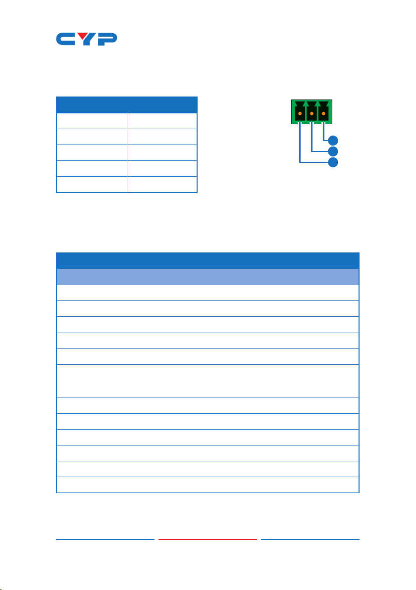
front panel buttons and RS-232.
2. APPLICATIONS
• Huddle Rooms & Small Boardrooms
• Entertainment Rooms & Home Theaters
• Lecture Hall Presentations
• Public Commercial Displays
• A/V Equipment and Control Rooms
3. PACKAGE CONTENTS
• 1× 2×1 HDMI/VGA to HDMI Scaler
• 1× 5V/2.6A DC Power Adapter
• 1× 3-pin terminal block
• 1× Shockproof Feet (Set of 4)
• 1× Operation Manual

2
4. SYSTEM REQUIREMENTS
• HDMI source equipment such as a media player, video game
console or set-top box.
• VGA source equipment such as a PC, laptop or set-top box.
• HDMI receiving equipment such as an HDTV, monitor or audio
amplier.
• The use of Premium High Speed HDMI cables is highly ecommended.
5. FEATURES
• HDMI 2.0 and DVI 1.0 compliant
• HDCP 1.x and 2.2 compliant
• Switchable HDMI input and VGA input with a 3.5mm mini-jack audio
input
• 1 HDMI output
• Supports up to 4K UHD (18Gbps, 4K@50/60Hz 4:4:4, 8-bit) video input
and output over HDMI
• Supports up to 1080p or WUXGA (1920x120060Hz RB) video input
over VGA
• Supports Deep Color input up to 12-bit (HDMI only)
• Supports 2 channel LPCM digital audio input and output
• Analog stereo audio may be embedded with either input
• Automatic input detection with output at the (EDID indicated)
preferred resolution of the connected HDMI display (NATIVE output
mode) by default
• Comprehensive output picture adjustments via RS-232 (contrast,
brightness, hue, saturation, sharpness, RGB (color tone) level and
aspect ratio)
• Controllable via front panel buttons and RS-232

3
6. OPERATION CONTROLS AND FUNCTIONS
6.1 Front Panel
POWER
HDMI OUT
AUTO ADJ. IN SEL.
SERVICE
VGA
HDMI TR
RS-232
G
1 2 3 4 5 6
1POWER LED: This LED will illuminate to indicate the unit is on and
receiving power.
2HDMI OUT Port: Connect to an HDMI TV, monitor, or amplier for
digital video and audio output.
3AUTO ADJ. Button: Press this button to activate the Auto Adjust
function for VGA sources.
Note: The Auto Adjust function requires a VGA source with a bright,
edge-to-edge, image to accurately judge the dimensions of the
signal.
4IN SEL. Button & LEDs: Press this button to toggle between the
available inputs. The LED will illuminate to indicate which source is
currently selected.
5RS-232 Terminal Block: Connect directly to a PC, laptop, or other
serial control device with a 3-pin adapter cable to send RS-232
commands to control the unit.
6SERVICE Port: This port is reserved for rmware update use only.

4
6.2 Rear Panel
HDMI IN VGA IN AUDIO IN DC 5V
12 3 4
1HDMI IN Port: Connect to HDMI source equipment such as a media
player, game console or set-top box.
2VGA IN Port: Connect to VGA source equipment such as a PC or
laptop.
3AUDIO IN Port: Connect to the stereo analog output of a device
such as an audio player or PC.
Note: By default, analog audio is embedded with the VGA input.
4DC 5V Port: Plug the 5V DC power adapter into this port and
connect it to an AC wall outlet for power.

5
6.3 RS-232 Pinout and Defaults
SERIAL PORT DEFAULT SETTINGS
1
2
3
RxD
GN
D
TxD
3-pin Terminal Block
Baud Rate 19200
Data Bits 8
Parity Bits None
Stop Bits 1
Flow Control None
6.4 RS-232 Commands
COMMAND
Description and Parameters
help
Show the full command list.
?
Show the full command list.
help N1
Show help details about command N1.
N1 = {Command name}
get fw ver
Show the unit’s current rmware version.
get model type
Show the unit's product type.
set factory default
Reset the unit to the factory defaults.

6
COMMAND
Description and Parameters
set uart 1 baudrate N1
Set the baud rate of the RS-232 port.
Available values for N1:
1 [4800 baud]
2 [9600 baud]
3 [19200 baud]
4 [38400 baud]
5 [57600 baud]
6 [115200 baud]
set uart 1 stop bit N1
Set the number of stop bits for the RS-232 port.
N1 = 1 ~2 [Stop bits]
get uart 1 stop bit
Show the current number of stop bits of the RS-232 port.
set uart 1 data bit N1
Set the data bits for the RS-232 port.
N1 = 5 ~ 8 [Data bits]
get uart 1 data bit
Show the current number of data bits of the specied RS-232
port.
set uart 1 parity N1
Set the parity of the RS-232 port.
Available values for N1:
0 [None]
1 [Odd]
2 [Even]
3 [Disable]

7
COMMAND
Description and Parameters
get uart 1 parity
Show the current parity setting of the RS-232 port.
set out A route N1
Route the specied input to the HDMI output.
Available values for N1:
1 [HDMI input]
2 [VGA input]
get out A route
Show the current input routed to the HDMI output.
set out auto mode N1
Set the auto switching/scanning behavior of the unit.
Available values for N1:
0 [Off]
1 [Auto Switch]
2 [Auto Scan]
get out auto mode
Show the current auto switching/scanning mode of the unit.
get out auto mode list
List all available auto mode options.
get in N1 sync status
Show the current sync state of the specied input.
Available values for N1:
1 [HDMI input]
2 [VGA input]
get out A sync status
Show the current sync state of the HDMI output.

8
COMMAND
Description and Parameters
get in N1 timing string
Show the index number and description of the current resolution
detected on the specied input.
Available values for N1:
1 [HDMI input]
2 [VGA input]
set automation event N1 uart A N2
Enable or disable the specied Automation Event's RS-232
response.
Available values for N1:
0 [Power on]
1 [Out A source active]
2 [Out A source lost]
Available values for N2:
ON [Enabled]
OFF [Disabled]
get automation event N1 uart A
Show the current state of the specied Automation Event's RS
232 response.
Available values for N1:
0 [Power on]
1 [Out A source active]
2 [Out A source lost]

9
COMMAND
Description and Parameters
set automation event N1 uart A command N2
Set the RS-232 command string to send when the specied
Automation Event is activated.
Available values for N1:
0 [Power on]
1 [Out A source active]
2 [Out A source lost]
N2 = {ASCII command string}
get automation event N1 uart A command
Show the RS-232 command string to be sent when the specied
Automation Event is activated.
Available values for N1:
0 [Power on]
1 [Out A source active]
2 [Out A source lost]
set automation event N1 uart A delay N2
Set the delay time that the specied Automation Event
must continue to be true before sending the dened RS-232
command.
Available values for N1:
0 [Power on]
1 [Out A source active]
2 [Out A source lost]
N2 = 0 ~ 240 [Delay in seconds]

10
COMMAND
Description and Parameters
get automation event N1 uart A delay
Show the delay time for the specied Automation Event's RS 232
response.
Available values for N1:
0 [Power on]
1 [Out A source active]
2 [Out A source lost]
set automation event N1 uart A wait N2
Set the length of time to wait after an Automation Event's RS
232 response has been activated before ANY other Automation
Event can be detected.
Available values for N1:
0 [Power on]
1 [Out A source active]
2 [Out A source lost]
N2 = 0 ~ 240 [Wait in seconds]
get automation event N1 uart A wait
Show the wait time for the specied Automation Event's RS 232
response.
Available values for N1:
0 [Power on]
1 [Out A source active]
2 [Out A source lost]

11
COMMAND
Description and Parameters
set out A timing N1
Set the output resolution to use on the HDMI output.
Available values for N1:
0 [Native]
1 [640x480p60]
2 [800x600p60]
3 [1024x768p60]
4 [1280x768p60]
5 [1280x800p60]
6 [1280x1024p60]
7 [1360x768p60]
8 [1400x1050p60]
9 [1440x900p60]
10 [1600x1200p60]
11 [1680x1050p60]
12 [1920x1200p60 RB]
13 [2560x1600p60 RB]
14 [1920x1080p60]
15 [1280x720p60]
16 [2048x1080p50]
17 [2048x1080p60]
18 [2560x1440p60 RB]
19 [720x480p60]
20 [1280x720p60]
21 [1920x1080p60]
22 [720x576p50]
23 [1280x720p50]

12
COMMAND
Description and Parameters
24 [1920x1080p50]
25 [1920x1080p24]
26 [1920x1080p25]
27 [1920x1080p30]
28 [2560x1080p50]
29 [2560x1080p60]
30 [3840x2160p24]
31 [3840x2160p25]
32 [3840x2160p30]
33 [3840x2160p50]
34 [3840x2160p60]
35 [4096x2160p24]
36 [4096x2160p25]
37 [4096x2160p30]
38 [4096x2160p50]
39 [4096x2160p60]
get out A timing
Show the current resolution used by the HDMI output.
set out A contrast N1
Set the contrast level of the HDMI output.
N1 = 0 ~ 60 [Contrast]
get out A contrast
Show the current contrast level of the HDMI output.
set out A brightness N1
Set the brightness level of the HDMI output.
N1 = 0 ~ 60 [Brightness]

13
COMMAND
Description and Parameters
get out A brightness
Show the current brightness level of the HDMI output.
set out A saturation N1
Set the saturation level of the HDMI output.
N1 = 0 ~ 60 [Saturation]
get out A saturation
Show the current saturation level of the HDMI output.
set out A hue N1
Set the hue value of the HDMI output.
N1 = 0 ~ 60 [Hue]
get out A hue
Show the current hue value of the HDMI output.
set out A sharpness N1
Set the sharpness level of the HDMI output.
N1 = 0 ~ 60 [Sharpness]
get out A sharpness
Show the current sharpness level of the HDMI output.
set out A nr N1
Set the amount of noise reduction to apply to the HDMI output's
source.
N1 = 0 ~ 4 [Noise reduction]
get out A nr
Show the current amount of noise reduction applied to the HDMI
output's source.

14
COMMAND
Description and Parameters
set out A aspect ratio N1
Set the aspect ratio of the video shown on the HDMI output.
Available values for N1:
0 [Overscan]
1 [Full]
2 [Best t]
3 [Pan scan]
4 [Letterbox]
5 [Under 2]
6 [Under 1]
7 [Follow In]
get out A aspect ratio
Show the currently set aspect ratio for the video shown on the
HDMI output.
get out aspect ratio list
List all available aspect ratio options.
set out A auto sync off N1
Enable or disable the Auto Sync Off function on the HDMI output
and set the timeout length.
Available values for N1:
0 [Disabled]
1 ~ 250 [Enabled with timeout in seconds]
get out A auto sync off
Show the current Auto Sync Off settings for the HDMI output.
set out A r gain N1
Set the HDMI output's red gain level.
N1 = 0 ~ 1023 [Red gain]

15
COMMAND
Description and Parameters
get out A r gain
Show the HDMI output's current red gain level.
set out A g gain N1
Set the HDMI output's green gain level.
N1 = 0 ~ 1023 [Green gain]
get out A g gain
Show the HDMI output's current green gain level.
set out A b gain N1
Set the HDMI output's blue gain level.
N1 = 0 ~ 1023 [Blue gain]
get out A b gain
Show the HDMI output's current blue gain level.
set in 2 phase N1
Set the PC phase value for the VGA input.
N1 = 0 ~ 250 [PC phase]
get in 2 phase
Show the current PC phase value for the VGA input.
set in 2 clock N1
Set the PC clock value for the VGA input.
N1 = 0 ~ 250 [PC clock]
get in 2 clock
Show the current PC clock value for the VGA input.
set in 2 hposition N1
Set the PC horizontal position for the VGA input.
N1 = 0 ~ 250 [Horizontal position]
get in 2 hposition
Show the current PC horizontal position for the VGA input.
Table of contents
Other CYP Media Converter manuals