Bazooka Mardi Gras MGA4150 User manual


1
ENGLISH
Dear customer,
Congratulations on your purchase of a Bazooka high-performance amplifier. At Bazooka,
we are fanatics about accurate music reproduction. Your selection of our products for
your sound system indicates that quality sound is also important to you too. At SAS, we
take great pride in manufacturing revolutionary audio products, and through the years of
engineering expertise, hand craftsmanship and critical testing procedures, we have
created this high-performance series of amplifiers. We hope that you will take as much
pride in owning and using one of these high-quality audio products as we do designing and
manufacturing them.
When properly installed and operated, your Bazooka MGA amplifier will give you years of
clean uninterrupted sound reproduction. Therefore, we urge you to take a few minutes to
carefully read through this manual. It will explain all of the features of your amplifier and
help insure trouble free installation.
Sound can be deceiving. Over time your hearing comfort level adapts to higher volumes of
sound. What may have sounded normal can actually be too loud and harmful to your hearing.
Guard against this by setting your equipment at a safe level before your hearing adapts.
To establish a “safe level”,
Start with your volume control at a low setting.
Slowly increase the volume control until you can hear comfortably, clearly and
without distortion.
Once you have established a comfortable “sound level”, make a note of this
position and do not go above this setting
Taking a minute to do this will help prevent your hearing from being damaged and allow you
to enjoy listening to music throughout your lifetime.

2
ENGLISH
MGA AMPLIFIERS
SAFETY PRECAUTIONS
Fuse amplifiers power wire at the battery.
Be sure to fuse the power wire within 6” of the car's battery. This will protect the car's
battery in case of a short circuit between the power amplifier and battery. THIS IS A MUST,
the amplifier's built-in fuse will only protect the power amplifier not the car's battery!
Use high grade wire connectors.
To ensure maximum power transfer and secure safe connections, it is recommended to
use high grade barrier spades (for connection at amplifier if applicable) and terminal rings
(for connection at battery).
Do not run any wires underneath vehicle.
Exposed wires have a chance of being cut or damaged. It is best to run all wires through
the vehicle under the carpet and/or side panels. This leads to a cleaner installation and
less risk of damage.
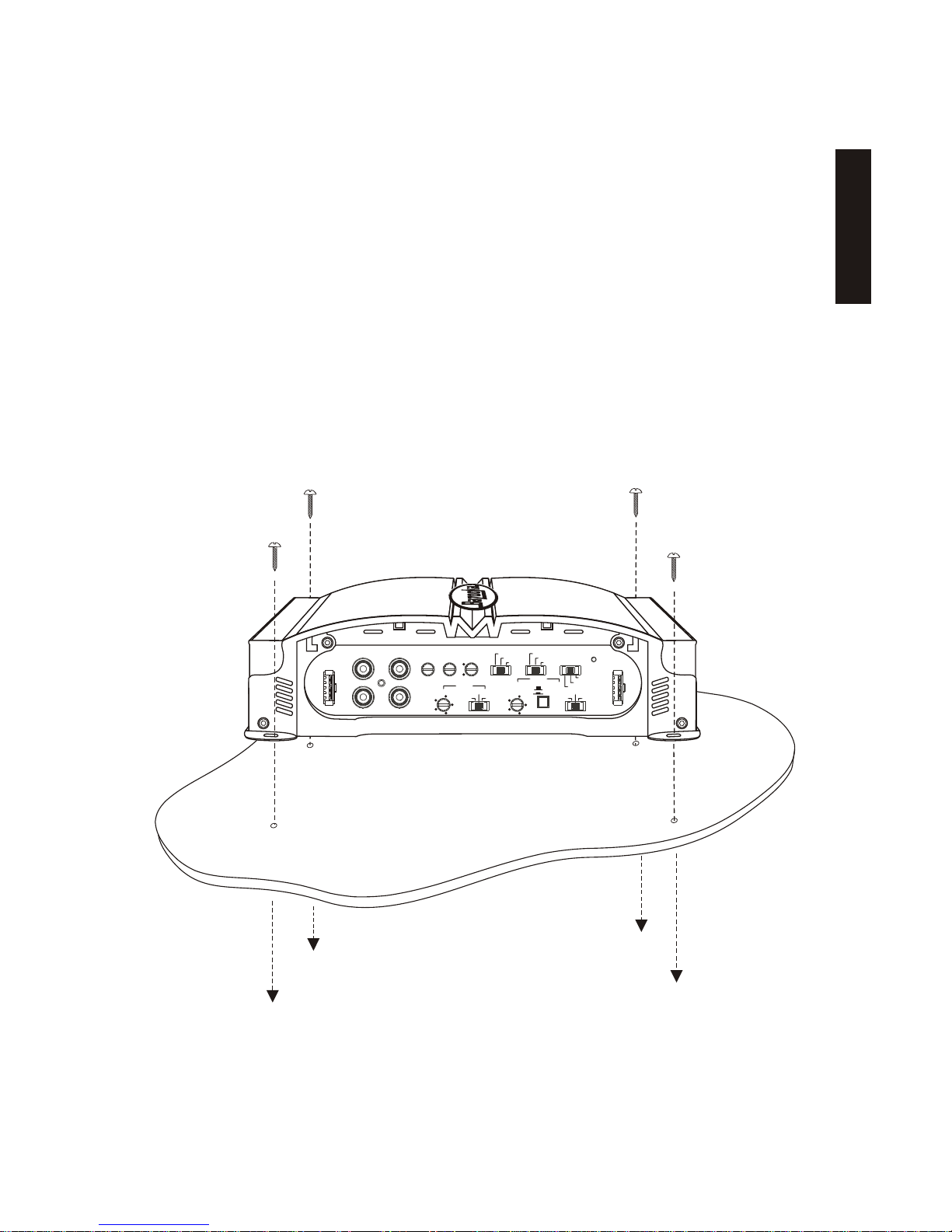
Use caution when mounting amplifier.
Remember there are many electrical wires, gas lines, vacuum lines, brake lines as well as a
gas tank in the automobile. Make sure you know where they are when mounting the
amplifier to avoid puncturing lines, shorting wires or drilling holes in the gas tank.
Run signal wires away from electrical wires.
To avoid possibility of induced noise from the car's electrical system (i.e. popping noises or
engine noise), run wires away from the car's electrical wiring.
Make all ground wires as short as possible and at the same point.
In order to reduce the chance of ground loops (i.e. engine noise), make the grounding wire
as short as possible to reduce the wire's resistance. Also, when using multiple
components, make sure all units are grounded at the same point.
Avoid sharp edges when running the wires.
To avoid the possibility of power, signal or speaker shorts, be careful not to allow the
amplifiers wires to come in contact with sharp edges. Use a grommet to protect the wire
when running through the fire wall .

3
ENGLISH
FEATURES AND BENEFITS
DC Offset Protection
This circuit protects the output of the amplifier against DC voltage. If for some reason DC
voltage is detected at the output stage, the amplifier will shut down protecting the
speakers from direct current.
Short Circuit Protection
This circuit protects the amplifier from damage due to a short found in the speakers or
wiring. If one of the speakers or its wiring comes in contact with ground, the amplifier will
shut down. To resume normal operation, correct the problem and turn the head unit off,
then back on. The amplifier will reset and play again.
Thermal Protection
To protect the amplifier circuitry against damage caused by prolonged exposure to high
temperatures, a thermal protection circuit is activated if the amplifier reaches
excessively high operating temperature. Once the thermal circuit is activated, the
amplifier will shut down to cool off. The amplifier will automatically turn back on once it
cools down to a safe operating temperature.
Built-in Crossover
The “MGA” amplifiers include a built-in variable high and low pass crossovers. The
crossover features a variable frequency selection (55Hz ~ 6kHz) for precise high or low
pass filtering.
Bass Boost
For added low frequency performance the amplifiers include a variable 0 ~16dB bass boost.
Power Fusing
This protects the amplifier against short circuits and excessive current.
Remote Turn-on
Automatically turns amplifier on when connected to the head unit's remote output. The
amplifier will turn on and off with the head unit to save current consumption. This control
also operates the reset circuit for the amplifier's protection. It must be connected with
the head unit in order to reset protection circuits.
Adjustable Input Sensitivity
Allows you to fine-tune the level matching between your source and the power amplifier.

4
ENGLISH
MGA AMPLIFIERS
MOUNTING LOCATION
Before you start the installation, it will be necessary to find a mounting location for the
amplifier. Find a location in which the amplifier will receive adequate ventilation in order
to dissipate the heat it develops during operation. Two popular mounting locations are in
the trunk or under the seat.
Select the location in which you wish to mount the amplifier. Use caution when mounting
amplifier, there are many wires, gas lines, vacuum lines, brake lines as well as a gas tank in
the automobile. Make sure you know where they are when mounting the amplifier to avoid
puncturing lines, shorting wires or drilling holes in the gas tank. Once you are ready, use a
pencil to mark the mounting holes in the bottom panel. After you have marked the locations
of the holes move amplifier out of the way and drill small starter holes to make the tapping
screws easier to install. Use provided screws to tighten down the amplifier.
0
16
dB
FREQ Hz
55 55
110 110
600 600
330 330
240 240
X 10
X 1
FREQ RANGE
FREQ Hz
POWER
FRONT
GAIN
FRONT REAR REAR
GAIN
L
R
INPUT FRONT
FRONT
L+R MONO
L+R MONO
STEREO
STEREO
BRIDGED (F R IN)
BRIDGED (F L IN)
REAR
REAR
4 CH.
2 CH.
HIGH FULL
LOW
HIGH
SOURCE
2 CH. BASS
+
-
RL
RR
REAR
SPEAKER
LEVEL IN
+
-
+
-
FL
FR
+
-
GND GND
FRONT
SPEAKER
LEVEL IN
(2 CH. IN)
FULL
LOW
BASS
BOOST

5
ENGLISH
CONNECTIONS
Panels slide off to make connections easier.
Be sure not to break plastic locking tabs!
Rubber plugs can be removed to reveal
channels for C.H.I.L water cooling kit!
Removing these plugs makes panel removal
easier.

30 AMP X 2 MAX +12V GND
TURN
ON
REAR
FRONT
LEFT RIGHT
2
2
CHIL
BRIDGED MIN
4
6
ENGLISH
MGA AMPLIFIERS
CAR BATTERY
+12V
CAR BATTERY
+12V
--
++
POWER CONNECTIONS
RADIO'S REMOTE
TURN-ON OUTPUT
RADIO'S REMOTE
TURN-ON OUTPUT
Connect the amplifier to the car's battery.
Connect the ground terminal of the amplifier to the car's chassis.
For the ground connection, use an 4 gauge wire (black) to connect to the terminal marked
GND and then connect it to the car's chassis. Try to keep the length of the cable as short as
possible, preferably less than 6". Also make sure that the point on the car where the
connection is to be made is free of paint and dirt.
Connect the remote terminal of the amplifier to a switchable +12V source.
This connection allows the amplifier to be turned on and off with the power control of the
radio. If the radio has a REMOTE output terminal, connect it to the amplifier's terminal
marked “TURN-ON” (using a 16 gauge wire or heavier). Now when the radio is turned on, the
amplifier will automatically turn on.
Make your power connections using a 4 gauge power wire for your connections. Strip one
end of the wire to connect to the terminal on the amplifier marked “+12V”. Loosen screw
terminal and connect bare wire and tighten. Use caution to make sure no stray wire
strands come in contact with surrounding terminals causing short circuits. Run the wire
directly to the positive terminal of the car's battery. Make sure to use an in-line fuse
within 6” of the car's battery to protect the electrical system and amplifier against short
circuits and/or power surges.
IMPORTANT! Before making any connections, disconnect the car’s battery until the
installation is completed to avoid possible damage to the electrical system.
94.794.7
IN-LINE POWER FUSE
MOUNTED WITHIN 6”
FROM BATTERY RECOMMENDED
IN-LINE POWER FUSE
MOUNTED WITHIN 6”
FROM BATTERY RECOMMENDED
(NOT PROVIDED)(NOT PROVIDED)

0
16
dB
FREQ Hz
55 55
110 110
600 600
330 330
240 240
X 10
X 1
FREQ RANGE
FREQ Hz
POWER
FRONT
GAIN
FRONT REAR REAR
GAIN
L
R
INPUT FRONT
FRONT
L+R MONO
L+R MONO
STEREO
STEREO
BRIDGED (F R IN)
BRIDGED (F L IN)
REAR
REAR
4 CH.
2 CH.
HIGH FULL
LOW
HIGH
SOURCE
2 CH. BASS
+
-
RL
RR
REAR
SPEAKER
LEVEL IN
+
-
+
-
FL
FR
+
-
GND GND
FRONT
SPEAKER
LEVEL IN
(2 CH. IN)
FULL
LOW
BASS
BOOST
7
ENGLISH
SIGNAL CONNECTIONS
Connect the RCA output of the head unit (AM/FM cassette player, CD, or DAT) to the RCA
input terminals of the amplifier.
To make these connections, we recommend high quality RCA cables, which are available at
your local car audio retailer. Run signal wires away from electrical wires to avoid
possibility of induced noise from the car's electrical system (i.e. popping noises or engine
noise). Please note that when making these connections the signal inputs correspond with
the speaker outputs.
FOUR CHANNEL INPUT
TWO CHANNEL INPUT
FRONT
RR
LL
RR
LL
REAR
LL
RR
PLEASE SEE INPUT CONFIGURATION
SETTINGS ON PAGE 10

0
16
dB
FREQ Hz
55 55
110 110
600 600
330 330
240 240
X 10
X 1
FREQ RANGE
FREQ Hz
POWER
FRONT
GAIN
FRONT REAR REAR
GAIN
L
R
INPUT FRONT
FRONT
L+R MONO
L+R MONO
STEREO
STEREO
BRIDGED (F R IN)
BRIDGED (F L IN)
REAR
REAR
4 CH.
2 CH.
HIGH FULL
LOW
HIGH
SOURCE
2 CH. BASS
+
-
RL
RR
REAR
SPEAKER
LEVEL IN
+
-
+
-
FL
FR
+
-
GND GND
FRONT
SPEAKER
LEVEL IN
(2 CH. IN)
FULL
LOW
BASS
BOOST
8
ENGLISH
MGA AMPLIFIERS
WHITEWHITE
RIGHT +RIGHT +
LEFT +LEFT +
BLACKBLACK
BLACKBLACK
WHITE/BLACKWHITE/BLACK
WHITEWHITE RIGHT +RIGHT +
LEFT +LEFT +
GROUNDGROUND
GROUNDGROUND
COMMON GROUND RADIO
94.794.7
FLOATING GROUND RADIO (MOST COMMON TYPE)
RIGHT +RIGHT +
RIGHT -RIGHT -
WHITEWHITE
WHITE/BLACKWHITE/BLACK
(NOT USED)(NOT USED)
BLACK (GROUND)BLACK (GROUND)
RIGHT +RIGHT +
RIGHT -RIGHT -
LEFT -LEFT -
LEFT +LEFT +
WHITEWHITE
WHITE/BLACKWHITE/BLACK
(NOT USED)(NOT USED) BLACK (GROUND)BLACK (GROUND)
94.794.7
LEFT -LEFT -
LEFT +LEFT +
GRAY/BLACKGRAY/BLACK
GRAYGRAY
GRAYGRAY
GRAYGRAY
GRAYGRAY
High Level inputs have been included to connect the amplifier to a radio without low-level
outputs (i.e. factory radio). This connection will allow you to connect directly to the
speaker output of the radio with out the need of an external adapter.
Determine the type of radio you have and make one of the following connections.
HIGH LEVEL CONNECTIONS (OPTIONAL)
CAUTION! Before making any connections determine the type of radio to avoid possible
damage to amplifier and/or radio.
PLEASE SEE INPUT CONFIGURATION
SETTINGS ON PAGE 10

30 AMP X 2 MAX +12V GND
TURN
ON
REAR
FRONT
LEFT RIGHT
2
2
CHIL
BRIDGED MIN
4
30 AMP X 2 MAX +12V GND
TURN
ON
REAR
FRONT
LEFT RIGHT
2
2
CHIL
BRIDGED MIN
4
9
ENGLISH
Make the speaker connections using speaker wire that is at least 16 gauge or heavier.
As with any audio component, proper phasing of the amplifier and speakers is essential for
strong bass response. When connecting, make sure that positive (+) from the amplifier is
connected to the positive (+) of the speaker, and the same for negative (-).
SPEAKER CONNECTIONS
4 Ohm
(2 Ohm Minimum)
4 Ohm
(2 Ohm Minimum)
4 Ohm
(2 Ohm Minimum)
4 Ohm
(2 Ohm Minimum)
SPEAKER CONNECTIONS (BRIDGED)
The MGA amplifiers are capable of being bridged in a mono configuration. This feature
allows you the flexibility of using the amplifier to drive a ** subwoofer or a center channel.
In this configuration the amplifier sums the right and left channel to deliver one channel
(mono) output.
**CAUTION! In the bridged mode, the amplifier must see the recommended minimum
impedance or higher. Any lower than the recommended minimum impedance will cause the
amplifier to overheat and possibly cause permanent damage to the amplifier!
8 Ohm
(4 Ohm Minimum)
8 Ohm
(4 Ohm Minimum)

10
ENGLISH
MGA AMPLIFIERS
GAIN
Fine tune the amplifier's input sensitivity.
The gain sensitivity control for the “MGA”
amplifier is located on the side panel. This gain control
has been included to allow adjustment to properly
match the output of the radio. This is one of the most
misunderstood adjustments. By rotating the control in
the clockwise direction, the amplifier‘s input will
become more sensitive and the music will play louder. This is
not a volume control and you will not get more power out of the amplifier in the maximum
position! It may seem to deliver more output, but actually the system is only playing louder
faster as you turn the volume control on the radio. Ideally, to properly level match the
system the goal is to achieve maximum output from the amplifier without distortion at
about 3/4 of the volume control.
To determine if the amplifier’s gain is set properly, turn the system on and slowly increase
the volume control. You should be able to use about 3/4 volume before the system gets loud
but not distorting. It is very important when making these adjustments that you do not
over drive the speakers (at point of distortion) this will cause permanent damage to the
speakers. If you are unable to achieve 3/4 volume before distortion you will need to
adjust gain control (in this case you would reduce the gain). The gain controls should be
adjusted very slowly. It may help to have another person to assist you by adjusting the
gain controls while you listen for distortion.
FINE TUNE THE SYSTEM
Select the crossover type for the
front speakers
Select the crossover type for the
rear speakers
Select the crossover
point for your front speakers.
Select the crossover
point for your rear speakers.
X-over Frequency Multiplier
Out = X1 (55Hz - 600Hz)
In = X10 (550Hz - 6Khz)
Select the source input
2 CH. BASS = 2 channel input with bass boost on front and rear channels
2 CH = 2 channel input with bass boost on the front channel
4 CH = 4 channel input with bass boost on front channels only Select the operation mode for the
front and rear channels
ADJUSTING THE X-OVER AND BASS
You can add up to 16dB of bass boost
by adjusting the Bass Boost control.
0
16
dB
FREQ Hz
55 55
110 110
600 600
330 330
240 240
X 10
X 1
FREQ RANGE
FREQ Hz
POWER
FRONT
FRONT
L+R MONO
L+R MONO
STEREO
STEREO
BRIDGED (F R IN)
BRIDGED (F L IN)
REAR
REAR
4 CH.
2 CH.
HIGH FULL
LOW
HIGH
SOURCE
2 CH. BASS
FULL
LOW
BASS
BOOST

11
ENGLISH
TROUBLE SHOOTING THE SYSTEM
We have put together this trouble-shooting guide if you experience problems after
installing the amplifier. Please keep in mind that the majority of problems incurred are
caused by improper installation and not the equipment itself. In addition, there are many
components in the system that could cause various signal problems such as inducted
electrical noise and engine noise.
Before you can properly address the problem, you must first find the component that is
causing the problem. This will take patience and a process of elimination.
LOOK FOR.... SOLUTION
No Output
Blown fuse Replace
Bad RCA Cable(s) Replace
+12V at power terminal Check connection
+12V at remote terminal Check connection
Grounding point clean and tight Check for ground w/meter
Head Unit's fader not in center position Set to center position
Low Output
Check level adjustments Re-adjust
Bad RCA cable(s) Replace
Improper level matching Re-adjust
Engine Noise
Grounding points are clean and tight Check for ground w/meter
Ground all components at same point Ground at same point
Try different grounding point Change for better ground
Bad RCA cable(s) Replace
Use High Quality shielded RCA cables Rejects inducted noise
Low Vehicle charging system and/or battery Fix and/or replace
Protection L.E.D. Illuminated
Speaker short Check speakers connection
for short circuit
Speaker grounding out Make sure speaker wires
do not touch chassis ground
Impedance too low Check speaker impedance
(Min 2 ohm Stereo, 4 Mono)
Overheating Check mounting location
for Adequate air Circulation
Speaker impedance too low

12 MGA AMPLIFIERS
ENGLISH
SPECIFICATIONS
MGA4150
Output Power @ 14.4 VDC :
4ohm...................................................................................100Wx4
2ohm...................................................................................150Wx4
Briged4Ohm............................................................................270Wx2
FrequencyResponse ...........................................................................10Hz-20KHz
S/NRatio(A-weight) ................................................................................<100dB
THD (A-weight).....................................................................................0.30%
LowInputLevel..................................................................................250mV-6V
HiInputLevel ..................................................................................400mV-12V
BatteryVoltageRange .......................................................................10.5VDC-15VDC
CrossoverType ................................................................................HP/FULL/LP
CrossoverFreq.Range(X1)......................................................................55Hz-600Hz
CrossoverFreq.Range(X10).....................................................................550Hz-6kHz
CrossoverSlope..................................................................................12dB/Oct
BassEQBoost......................................................................................0-16dB
Fuse ..........................................................................................30Ax2
Due to continuing product improvement, specifications subject to change without notice.

13
ENGLISH
LIMITED WARRANTY
Southern Audio Services, Inc., warrants all products to be free from defects in
material and workmanship for a period of one (1) year from the date of purchase. In
the event the product is not as warranted, SAS’ sole obligation shall be to repair or
replace the defective product at SAS’ option: SAS limits its obligation under any
implied warranties under state laws to a period not to exceed the limited warranty
period. SAS and its authorized BAZOOKA® dealers specifically disclaim liability for
any incidental or consequential damages. Some states do not allow limitations on
how long an implied warranty lasts, and some states do not allow the exclusion or
limitation of incidental or consequential damages, so the above limitation or
exclusions may not apply to you. This warranty gives you specific legal rights, and
you may have other rights, which vary from state to state.
What is covered: This warranty covers all defects in materials or workmanship
(parts and labor) in the product.
What is not covered: This warranty does not cover the following:
1. Damages occurring during shipment of the product to SAS for repair
(Claims must be presented to the carrier).
2. Damages caused by accident, abuse, negligence, misuse or improper
Operation or installation.
3. Damages caused by an act of God, including without limitation, fire, flood
Storm or other acts of nature.
4. Any product, which has a serial number, defaced, altered, modified, or
removed.
5. Any product that has been altered or modified without SAS’ consent.

ENGLISH
14 MGA AMPLIFIERS
How to obtain warranty services:
1. You are responsible for delivery of the product to an authorized BAZOOKA® dealer
or contact SAS at 1-800-THE TUBE for a Return Authorization number. The Return
Authorization number must be clearly written on the outside of the box. Freight must
be prepaid to SAS. Warranty replacement parts will be returned freight prepaid. The
entire enclosure may be returned for warranty service, but return will be freight
collect.
2. You must provide proof of the date of purchase of the product. If proof of
purchase is not provided, original date of manufacture will be used to determine
warranty period.
3. You must package the product securely to avoid damage during shipment.
4. After acquiring a Return Authorization number, ship to the address below. Please
complete this section and retain for your records.
Model(s) purchased ________________________________________________________
Serial number(s) __________________________________________________________
Date Purchased ___________________________________________________________
Dealer’s name ____________________________________________________________

15
Chère cliente, Cher client,
Félicitations! Vous venez d'acquérir un amplificateur haute-performance de la marque
Bazooka. Chez Bazooka, nous attachons une grande importance à la reproduction musicale
de précision. Le fait que vous ayez choisi nos produits pour votre chaîne audiophonique
indique que, pour vous aussi, la qualité sonore a de l'importance. Chez SAS, nous sommes
fiers de fabriquer des produits audio révolutionnaires et nos nombreuses années
d'expertise en ingénierie, notre savoir-faire artisanal et nos procédures de test critiques
nous ont permis de créer cette gamme d'amplificateurs haute-performance. Nous
espérons que vous serez aussi fiers de posséder et d'utiliser un de ces produits audio de
haute qualité que nous le sommes de les avoir conçus et fabriqués.
Bien installé et utilisé, votre amplificateur Bazooka MGA vous offrira des années de
reproduction sonore nette ininterrompue. C'est pourquoi nous vous recommandons
vivement de consacrer quelques minutes à la lecture approfondie de ce manuel. Il vous
détaillera toutes les caractéristiques de votre amplificateur et vous aidera à l'installer
sans incident.
Le son peut être trompeur. Avec le temps, votre confort auditif s'adapte à des volumes
sonores plus élevés. Ce qui a pu vous paraître normal peut être en réalité trop fort et
dangereux pour votre audition. Protégez-vous contre cela en réglant votre équipement
audio à un niveau sûr avant que votre oreille ne s'adapte.
Pour établir un «niveau sûr»,
Commencez en réglant votre commande de volume sonore sur un
réglage bas.
Augmentez doucement le volume jusqu'à ce que vous puissiez entendre
le son confortablement, clairement et sans distorsion sonore.
Une fois que vous avez établi un «niveau sonore» confortable, notez
cette position et ne dépassez pas ce niveau
Prendre une minute pour faire cela vous aidera à éviter d'endommager votre capacité
auditive et vous permettra d'avoir le plaisir d'écouter de la musique tout au long de votre
vie.
FRANÇAIS

16
FRANÇAIS
MESURES DE SÉCURITÉ
Installez des fusibles sur le câble d'alimentation des amplificateurs au niveau
de la batterie.
Assurez-vous d'installer des fusibles sur le câble d'alimentation à environ 12 pouces (30
cm) de la batterie du véhicule. Cela protègera la batterie du véhicule en cas de court-circuit
entre l'amplificateur de puissance et la batterie. CELA EST IMPÉRATIF. Le fusible intégré de
l'amplificateur ne protégera que l'amplificateur de puissance, pas la batterie du véhicule!
Utilisez des connecteurs de fil de catégorie supérieure.
Afin d'assurer un transfert de puissance maximum et des connexions sûres et sécurisées,
il est recommandé d'utiliser des cosses à fourche (à connecter sur l'amplificateur si
possible) et des cosses à oeil (à connecter sur la batterie) de catégorie supérieure.
Ne faites pas passer de câbles sous le véhicule.
Les câbles exposés courent le risque d'être coupés ou endommagés. Il est préférable de
faire passer les câbles dans le véhicule sous les tapis et/ou les parois latérales. Cela
conduit à une installation plus propre et réduit le risque d'endommagement.
Soyez prudent lors du montage de l'amplificateur.
N'oubliez pas qu'une automobile se compose de nombreux câbles électriques, de conduites
de carburant, de tuyauteries à dépression, de tuyauteries de frein ainsi que d'un réservoir
d'essence. Assurez-vous de connaître leur emplacement lorsque vous monterez
l'amplificateur afin d'éviter de crever des conduites, de couper des câbles ou de percer le
réservoir d'essence.
Écartez les fils de transmission de signaux des câbles électriques.
Pour éviter toute possibilité de bruit induit provenant du système électrique du véhicule (à
savoir, des craquements ou des bruits de moteur), éloignez les câbles du câblage électrique
du véhicule.
Assurez-vous que les fils de masse sont aussi courts que possible et reliés au
même point.
Afin de réduire les risques de boucle de masse (à savoir, bruit de moteur), assurez-vous
que le fil de masse est aussi court que possible pour réduire la résistance du fil. De même, si
vous utilisez plusieurs composants, assurez-vous que toutes les unités sont reliées à la
terre en un même point.
Évitez les arêtes vives lorsque vous tirez les câbles.
Afin d'écarter la possibilité de coupure de courant, de signal ou de haut-parleurs,
prenez soin de ne pas laisser les câbles des amplificateurs entrer en contact avec des
arêtes vives. Utilisez un anneau pour protéger le câble lorsqu'il traverse la cloison
pare-feu.
AMPLIFICATEURS MGA

17
FRANÇAIS
FONCTIONS ET AVANTAGES
Protection contre la tension continue
Ce circuit protège la sortie de l'amplificateur contre la tension continue. Si, pour quelque
raison que ce soit, une tension continue est détectée au niveau de la sortie, l'amplificateur
se ferme, protégeant les haut-parleurs du courant direct.
Protection de court-circuit
Ce circuit protège l'amplificateur des dommages dus à un court-circuit au niveau des haut-
parleurs ou du câblage. Si un des haut-parleurs ou son câblage entrait en contact avec la
masse, l'amplificateur se mettrait à l'arrêt. Pour reprendre un fonctionnement normal,
veuillez corriger le problème et éteindre l'unité principale, puis la rallumer. L'amplificateur
se réinitialisera et se remettra en mode de lecture.
Protection thermique
Pour protéger les circuits de l'amplificateur contre les dommages causés par une
exposition prolongée à des températures élevées, un circuit de protection thermique est
activé si l'amplificateur atteint une température de fonctionnement excessivement
élevée. Une fois le circuit thermique activé, l'amplificateur s'arrêtera pour refroidir.
L'amplificateur se rallumera automatiquement lorsqu'il aura de nouveau atteint une
température de fonctionnement sûre.
Filtre intégré
Les amplificateurs «MGA» sont dotés de filtres variables passe-bas et passe-haut**
intégrés. Ce filtre est doté d'une sélection de fréquence variable (55 Hz ~ 6 kHz) pour un
filtrage passe-bas ou passe-haut précis.
Intensification des basses
Pour une meilleure performance basses fréquences, les amplificateurs incluent une
intensification des basses variable de 0 ~16 dB
Fusibles de ligne
Ils protègent l'amplificateur contre les courts-circuits et le courant excessif.
Mise en route à distance
Met l'amplificateur en route automatiquement lorsqu'il est connecté à la sortie distante de
l'unité principale. L'amplificateur s'allumera et s'éteindra avec l'unité principale afin de
réduire la consommation de courant. Cette commande actionne également la
réinitialisation du circuit pour la protection de l'amplificateur. Il doit être connecté sur
l'unité principale afin de réinitialiser les circuits de protection.
Sensibilité d'entrée réglable
Vous permet de régler le niveau adapté entre votre source et l'amplificateur de
puissance.

18
FRANÇAIS
EMPLACEMENT DE MONTAGE
Avant de commencer l'installation, il sera nécessaire de trouver un emplacement de
montage pour l'amplificateur. Choisissez un endroit où l'amplificateur bénéficiera d'une
ventilation adéquate afin de dissiper la chaleur qu'il émet pendant son fonctionnement. Les
amplificateurs sont très couramment installés dans le coffre ou sous le siège.
Choisissez l'endroit où vous voulez monter l'amplificateur. Soyez prudent lors du montage,
une automobile se compose de nombreux câbles électriques, de conduites de carburant, de
tuyauteries à dépression, de tuyauteries de frein ainsi que d'un réservoir d'essence.
Assurez-vous de connaître leur emplacement lorsque vous monterez l'amplificateur afin
d'éviter de crever des conduites, de couper des câbles ou de percer le réservoir
d'essence. Une fois que vous êtes prêt, utilisez un stylo pour marquer les trous de fixation
sur le panneau du dessous. Une fois les emplacements des trous marqués, décalez
l'amplificateur et percez de petits trous d'amorce pour faciliter l'insertion des vis
autotaraudeuses. Utilisez les vis fournies pour installer l'amplificateur.
AMPLIFICATEURS MGA
0
16
dB
FREQ Hz
55 55
110 110
600 600
330 330
240 240
X 10
X 1
FREQ RANGE
FREQ Hz
POWER
FRONT
GAIN
FRONT REAR REAR
GAIN
L
R
INPUT FRONT
FRONT
L+R MONO
L+R MONO
STEREO
STEREO
BRIDGED (F R IN)
BRIDGED (F L IN)
REAR
REAR
4 CH.
2 CH.
HIGH FULL
LOW
HIGH
SOURCE
2 CH. BASS
+
-
RL
RR
REAR
SPEAKER
LEVEL IN
+
-
+
-
FL
FR
+
-
GND GND
FRONT
SPEAKER
LEVEL IN
(2 CH. IN)
FULL
LOW
BASS
BOOST

19
FRANÇAIS
CONNEXIONS
Les panneaux s'enlèvent latéralement pour faciliter les
branchements. Assurez-vous de ne pas casser les languettes
de blocage en plastique!
Les bouchons en caoutchouc peuvent être retirés afin de mettre à
jour les canaux pour la trousse de refroidissement par eau Chil!
Table of contents
Languages:
Other Bazooka Amplifier manuals

Bazooka
Bazooka ELA1190 User manual

Bazooka
Bazooka CSA-2 User manual

Bazooka
Bazooka Honda GL1800 (2001-2005) Audio Amplifier User manual

Bazooka
Bazooka CSA-2 User manual

Bazooka
Bazooka ELA1300 User manual

Bazooka
Bazooka GOLDWING GL1800 User manual

Bazooka
Bazooka ELA150.1 User manual

Bazooka
Bazooka MA1600D User manual

Bazooka
Bazooka Phat Tuesday MGA11000H User manual

Bazooka
Bazooka P250 User manual