ChapterTwo
FunctionsandOperationInstructions
2.1Features
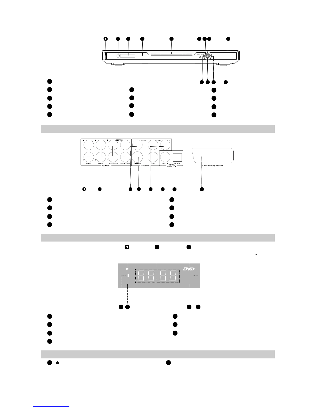
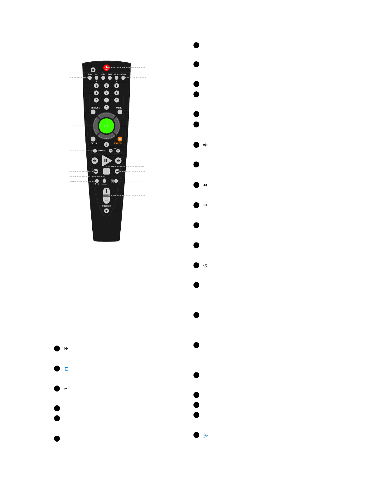
2.2ControlButtonLocationsandExplanations
ThisplayerhasemployedthenewgenerationDVdecodechipwithbuilt-inDolbyDigitaldecoder
whichwillbringyoutoabrand-newAVententainmentworld.The2-lasersupererror-correction
mechanismsupportsCD-R.
1.CompatiblewithDivX,MPEG4discstoproducewonderfulpictures.
2.108MHz/12bitvideoDAC,withmorevividandbrilliantpictures.
3.Progressive-scanvideooutputstoeliminatetheflickershardlyouvercomebyinterlacingscan
andthereforeyoureyesightwillbewell-protected.Atthesametime,thepicturesdeflnltionIssharply
enhancedandthepictureswillbefiner,smootherandstabler
4.Brightness,chromaandcontrastadjustmentfunctionstorenderyoureyesmorecomfortable.
5.DigitalechoKaraoketoenableyoursingingeasier.
6.CompositeVideo,S-VideoandComponentVideooutputs.
7.Bullt-InDolbyDigitaldecoder,separate5.1ChOutputs.
8.Dolbyoutputfor2channel(DOWNMIX)
9.DVD-Audiodecodingoutputtoreproduceoriginalandrealisticsoundeffects.
1.OpticalandcoaxialoutputsforDigitalaudio.
2.DTS,DoblyDigital,PCMDigitalaudiooutputstosatisfytheFans’Ssacousticrequirements.
1.Screensaverprotectsyour TVsetcarefully.
2.ThenovelMp3playbackwindowGUIprovidesyouanewwaytoappreciateMp3music.
3.Multi-angleplaybackfunctionmakesitpossibleforyoutoviewascenefromdifferentcamera
angles.
4.It’spossibletoselectthedesiredbeginning,developmentandendingofastory.
5.Directentryintodesiredscenes(title/chapter/tracksearch).
6.Zoomingfunctiontozoomupanyplayingpicture.
7.CapableofplayingPAL/NTSCdiscs.
8.MultipleaspectratiostofitTVsetsofvariousscreenratios.
9.Parentallockfunctiontopreventchildrenfromwatchingunsuitablediscs.
10.Multipledubbinglanguagesandsubtitlelanguagesbringyouthebestentertainmentstatusall
thetime.
NOTE:DivXversionisstillupgradingcontinuouslyandthelatestversionofthisunitisDivX5.1.
SomediscslabelledwithMPEG4onthemarketactuallyareothers,withwhichareuncompatible.
Pleasetakecarewhenbuyingdiscs.
Brand-newAVEffects
HighQualityDigitalAudio
ManyConvenientFeatures
SuperCompatibilitywithsuperVCD,VCD,CD,CD-R,MP3,HDCD,KODAKPICTURECDetc.
2.2.1FrontPanelIllustration
-4-