BBP BBP752-L-WML-F Series User manual
BBP752Lx-WML-Fx-r101123
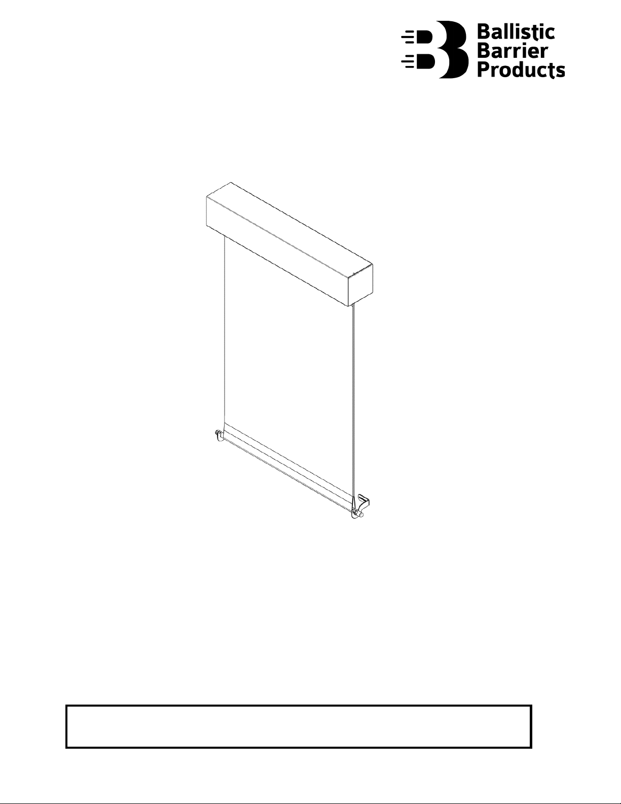
Bullet-Resistant
Locking Hem Bar, Motorized Window Shade
BBP752-Lx-WML-Fx
Contents
1. Part and Hardware List......................................................................................................... 2
2. Determine Mounting Points................................................................................................. 5
3. Wall Bracket and Shade Installation ..................................................................................... 7
4. Hem Bar Lock Installation................................................................................................... 10
5. Testing and Final Adjustments ........................................................................................... 14
6. Installation Certification..................................................................................................... 17
7. Warranty and Limit of Liability Information........................................................................ 17
If there are any issues during installation, please contact us at 833-285-5380
Monday – Saturday, 6 AM to 10 PM PST
2
1. Part and Hardware List
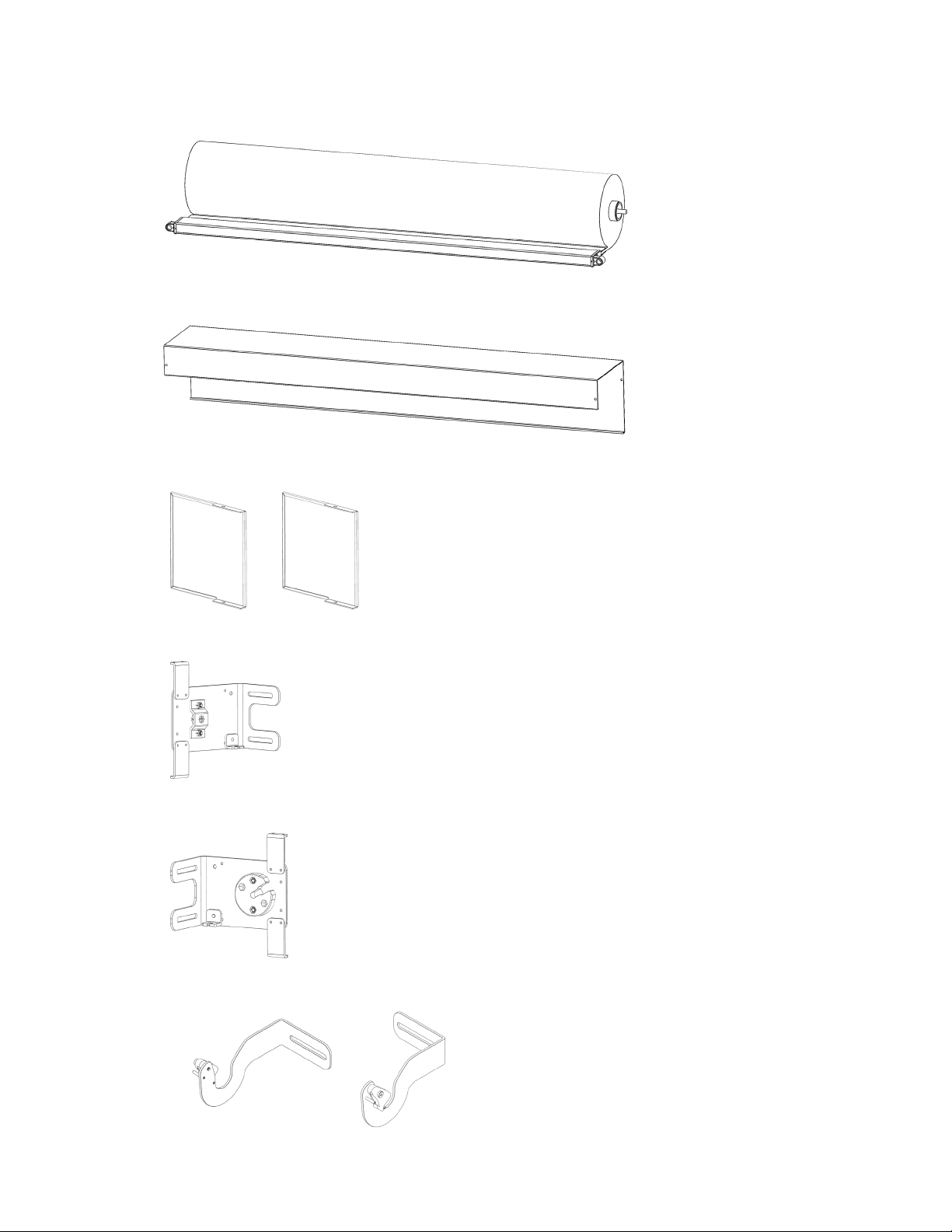
1) Shade (Roll Good) with Motor
2) Fascia
3) Sheet Metal End Covers (2)
4) Motor Side Wall Bracket
5) Idler Side Wall Bracket
6) Hem Bar Locks (one left and one right side)
3
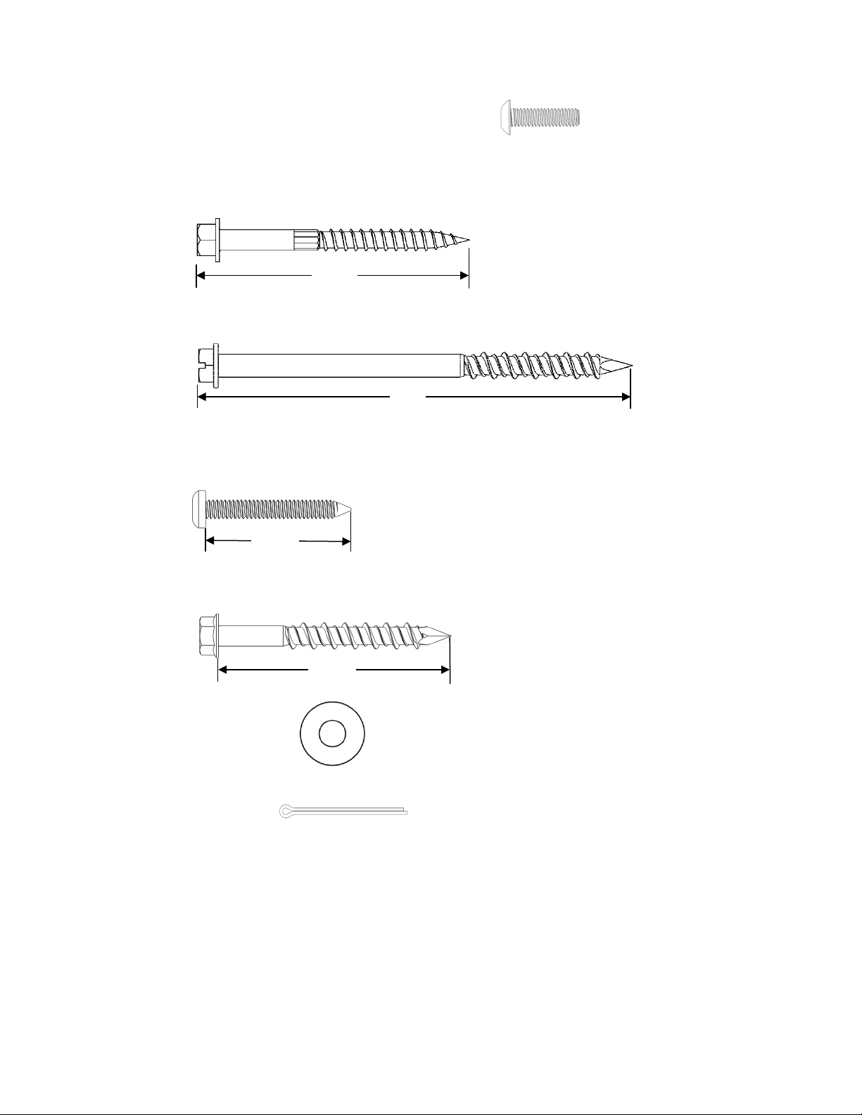
7) 8-32 Pan Head Screws x 5/8”, shown actual size (4)
8) One of the following, shown actual size:
1. For mounting into wood or steel studs, ¼” x 2½” self-drilling wood screws, qty 4.
2. For mounting into concrete or brick, ¼” x 4” concrete screw anchors, qty 4
9) One of the following, shown actual size:
1. For mounting into wood or steel studs, #10 x 1½” pan head screws, qty 4.
2. For mounting into concrete or brick, ¼” x 2¼” concrete screw anchors, qty 4
10) ¼" flat washer, qty 8
11) Steel cotter pin
4”
2½”
1½”
2¼”

4
Tools required
1) Mounting into concrete or brick, 3/16 drill bit for the 1/4” masonry bolts
2) 3/32” drill bit
3) 5/16" socket head driver
4) T25 Torx driver
5) Needle nose pliers
6) Tape measure
7) Straight edge or square for marking straight lines
8) A bubble level (at least 4 ft in length will be best)
9) Pencil for marking hole positions
10) Wood or steel stud construction: electronic stud finder or a 1/16” diameter drill
to drill test holes to find the studs.

5
2. Determine Mounting Points
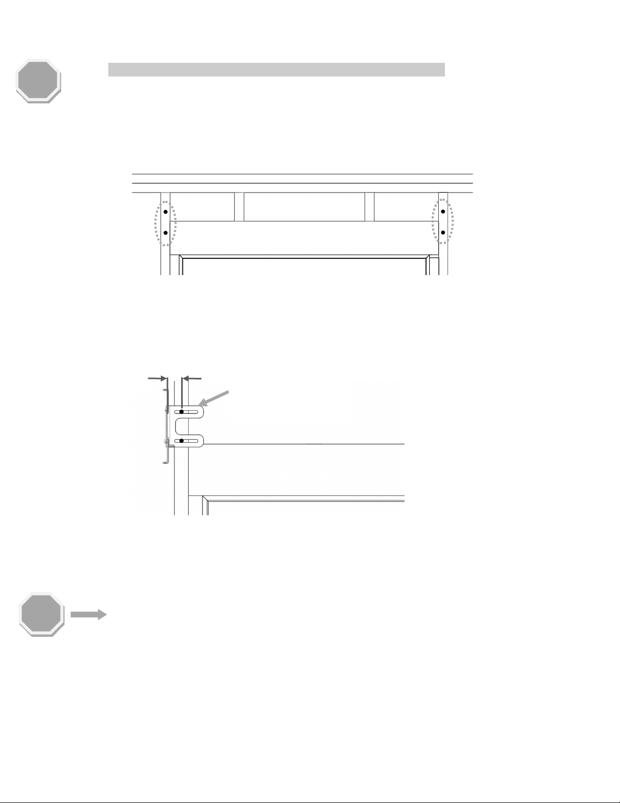
1) The Wall Brackets MUST attach to solid material in the zone depicted in the image at the
bottom of this page. This can be in either:
a) The horizontal header spanning the window frame
b) The vertical studs on the outside of the frame that run all the way to the floor
c) Solid masonry if the construction around the window frame is brick or
concrete.
2) Using the outside edges of the window frame (the vinyl, plastic, or aluminum portion) as the
starting point (not the window glass), mark the approximate locations of all four mounting
points shown on the right side of the image.
3) CRITICAL STEP:The effectiveness of the product in stopping handgun fire is dependent on
the brackets being mounted securely to the wall.
a) Confirm that the four mounting locations marked in step 2.2 will fully engage SOLID
material into which the mounting screws will be securely held (studs, headers, or
masonry construction) and NOT simply engage the sheetrock.
b) For wood or steel stud constructions, use a stud finder or drill small pilot holes to
determine the locations of the studs.
•Screws that only engage the edges of a stud will not have sufficient
holding strength and could fail in a shooting event.
c) If there is any doubt in the type of materials behind these mounting points, drill test
screws into the four locations and make sure the torque to drive these screws
reaches at least 7ft-lbs (10Nm).
d) If you are sure of the support the four mounting locations will provide, move to
Section 4; if not, finish Section 3.
STOP
STOP

6
4) If the measured mounting points do NOT allow drilling into solid material, try one of these
two methods to create a secure connection:
1If the mounting points appear to be in the area of the window frame header, but
the mounting screws are not engaging it, the header may not be flush to the near
side wall and out of reach, but a longer screw may allow proper engagement.
•Use an extended bit (3/32” dia. or smaller) and drill pilot holes at all of the
mounting points to determine if the header can be reached by simply drilling
deeper into the wall. If this is the case, longer mounting screws will be needed.
•If longer screws are purchased on your own,use a screw certified to a US
building standard, such as ICC-ES-2236.
oBBP recommends using Simpson Strong-Tie/Strong Drive® self-drilling wood
screws, available at most hardware stores.
oIf there is any issue obtaining screws of the appropriate strength or length,
contact the Ballistic Barriers helpline at (833) 285-5380.
2Hold one of the Wall Bracketsup so the slots align with the mounting locations. If
the position of any of the studs/header misses the mounting points but will sit
beneath an open area on the Wall Bracket, you may drill supplementary ⅜” holes
into the Wall Bracket that will allow screws to engage the studs/header.
•If this modification is pursued,you must photo document the placement of
the holes and submit them to Ballistic Barriers for certification.
If neither of these solutions will suffice, contact the Ballistic Barrier assistance line,
(833) 285-5380, Monday – Saturday, 6 AM to 10 PM PST. You can call this line at any
time outside of office hours and leave a message and the support team will make
every effort to return your call as soon as possible, no matter the time of day.
Most Common
Header
Header Set to
Far Wall,
Screw Cannot
Reach
Longer Screw
Engages Header
Okay to Drill New Mounting
Holes in the Areas Highlighted
In Dark Gray
Mounting Points in This Area
Will Not Fully Engage Studs or
Miss Studs Completely
STOP
STOP
7
3. Wall Bracket and Shade Installation
NOTE: The following images depict a motor with a left-side power cable.
•If your product has a right-side power cable, all installation images in this section will
mirror your actual components.
1) Drill pilot holes at each of the four mounting locations marked in Section 2.
•For concrete or brick, use a 3/16” drill bit.
•For wood or steel studs, use a 3/32” drill bit.
2) Align the left Wall Bracket (the Motor Side Wall Bracket for a left-side power cable
installation) so that the two slots are at the heights of the mounting points.
3) Adjust the horizontal position of the bracket so the inside face of the bracket is 1½” from
the mounting points (see image below).
4) Use a bubble level to ensure the bracket is level.
5) Drive the mounting screws into the bracket, one in each mounting slot.
•For wood or steel studs, use ¼” wood screw and washer.
•For concrete or brick, use a ¼” concrete screw anchor and washer, do not exceed 20
ft-lbs of torque when driving in the screw.
•If, for some reason, you cannot use the screws provided with the assembly, use
hardware that is certified to a high standard, such as ICC-ES-2236. As this a product
that is meant to stand up to bullet impacts, there is risk in using low-quality
hardware that is not made to meet US building codes.
For mounting screws, BBP recommends:
oSimpson Strong-Tie/Strong Drive® self-drilling wood screws
oTapcon® concrete screw anchors
6) Move to the right side of the Window and repeat the process for the right Wall Bracket.
1½”
Use a Bubble Level
to Confirm Bracket
is Level
STOP
STOP

8
7) Use a 4 ft bubble level to assure the two brackets are level with each other (if the brackets
are further than 4ft apart, span the gap with a flat, rigid material and place the level on that
material).
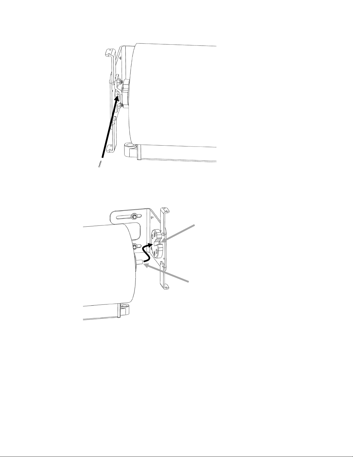
8) Lift the Shade up and work first on the power cable side of the roll and engage the Square
Male Motor Shaft into the mating Female Mounting Hole on the Motor Side Wall Bracket.
Use a 4ft Bubble Level
to Confirm Brackets Are Level
Square Male Motor Shaft
Mating Female Mounting Hole
Power Cable
Side of Shade
(Left-side Power Cable Shown)
9
9) Insert the Cotter Pin into the hole in the square male to hold that side of the Shade in
place.Do not bend the Cotter Pin legs yet.
10) On the opposite side of the Shade, press in the Spring-Loaded Idler Shaft and maneuver
the Shade so that shaft will sit in the mating cavity of the plastic Idler Mount.
Cotter Pin
Spring-Loaded Idler Shaft
Mating Idler Mount
Idler Side of Shade
(Left-Side Power Cable Shown)

10
4. Hem Bar Lock Installation
IMPORTANT TO UNDERSTAND:The Hem Bar Locks are optional to install; however, they are
recommended as they maximize the protection the shade will provide as they secure the
bottom of the shade in place when it is deployed.
•If the fabric is shot at, the impact of the bullet does cause the fabric to rise up as it
“catches” the bullets. The amount that it pops up is dependent on a number of
factors and is complicated enough that BBP can offer no exact data on the severity
other than to say, typically, 9mm rounds hitting a shade in quick succession from a
handgun, impacting the center of a 3ft x 4ft shade will see the shade lift up only a
few inches with each hit, and the lifting effecting is not necessarily cumulative with
each successive shot.
•If the bottom of the shade is secured by the Hem Bar Locks, the amount it can lift
up is negligible.
•The locks also keep the shade from being easily pushed out of the way by an
intruder.
•However, while the weight and momentum of the shade being lowered allows the
locks to open and engage the Hem Bar without any intervention, to raise the shade,
the locks must be disengaged manually by pushing the plastic latch back and
removing the Hem Bar from its grasp.
•If having a manual release poses a major issue, omitting the installation of the locks
can be deemed low (but not zero) risk of injury if at least three of these conditions
are met:
a) The bottom of the window is at the floor of the room and it is deemed
unlikely that a threat would be shooting that low to the ground.
b) A bullet entering the room near the bottom of the shade would pose a
threat that is manageable (the likelihood of a human target being near the
bottom of the shade is impractical).
c) The shade is well over 12 sq ft in size (large and heavy – the larger, the
better).
d) It is anticipated that the threats would be limited to lower caliber bullets
and semi-automatic only.
To install the Hem Bar Locks:
1) Power up the Shade and extend it to its full extent (to
operate the motor, see separate instructions for the
exact type of motor and switch model included with your
product).

11
2) IMPORTANT: Make sure the Hem Bar is centered in the shade.
3) Use the location of the Hem Bar to define the mounting position of the Hem Bar Locks:
1. Let the Shade hang down without any interference.
2. Place the left Hem Bar Lock so the latch is engaged on the Hem Bar such that
the inside edge of the sheet metal surface is approximately ¾” from the edge
of the fabric.
3. Place the mounting surface of the lock against the wall and make sure the
shade is hanging naturally in its deployed position as you do this.
4. Use a pencil to trace the interior of the mounting surface slot.

12
5. Remove the Hem Bar from the lock.
•Masonry walls: mark two drill locations within the area of the slot that
was marked on the wall and drill pilot holes with the 3/16” bit. The drill
locations can be anywhere in the slot, but should be at least 1½” apart.
•Wood or steel stud walls: use a stud finder or any other method to identify
where the wall studs lie in relation to the slot marked on the wall.Mark
two drill locations (at least 1½” apart from each other) anywhere in this
slot outline that are over the location of the wall studs.
It is critical that both of the screws are engaged into a solid mounting material
such as a stud or masonry. If you are unable to find a solid connection point
for the mounting holes, contact the Ballistic Barriers helpline at (833) 285-
5380.
4) Mount the left Hem Bar Lock to the wall by driving two of the screws with washers into the
two drill locations.
•Masonry walls: use the ¼” x 2¼” concrete anchor screws.
•Wood or steel stud walls: use the #10 x 1½”Torx pan head screws .
5) Repeat this entire process for the Hem Bar Lock on the right side of the Shade.
STOP

13
6) Test the function of the locks by raising and lowering the Shade into place several times
over. Each time it is lowered, the hem bar should lock into place on its own; each time it is
raised, the locks must be released manually by:
1. Pushing the sping-loaded latch back to disengage the bar.
2. Lifting the hem bar out of the lock.
14
5. Testing and Final Adjustments
1) Test the product and make sure that it runs fluidly, and that the cover goes all the way up
and down.
•Confirm the window can open and close satisfactorily with the cover completely
retracted.
•Once you are certain that no adjustments are needed, proceed to the next step, which
will install the Shaft Retainer and essentially lock the roll from coming out. After this
lock is in place, if there are any adjustments needed that would require removal of the
Shade, the entire product will have to be partially disassembled to remove the
Retainer as it can only be removed by sliding it out the side of the Idler Mount (it
cannot be pulled out the opposite direction it was inserted). If there is any doubt,
please contact our helpline at (833) 285-5380.
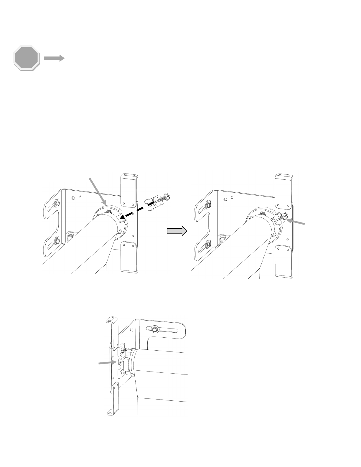
2) Place the fork-shaped Shaft Retainer into the slot of the Idler Mount and press it into place.
If the screw has not been sufficiently backed out, the two arms of the fork will not compress
enough to allow the Retainer to be pushed into place.
3) Tighten the screw on the Shaft Retainer several turns to secure it into place.
4) Use a pair of needle nose pliers to bend the legs of the motor mount Cotter Pin so it will stay
in place.
②
①
Insert Retainer
Tighten Screw
Idler Mount
Cotter Pin
STOP
15
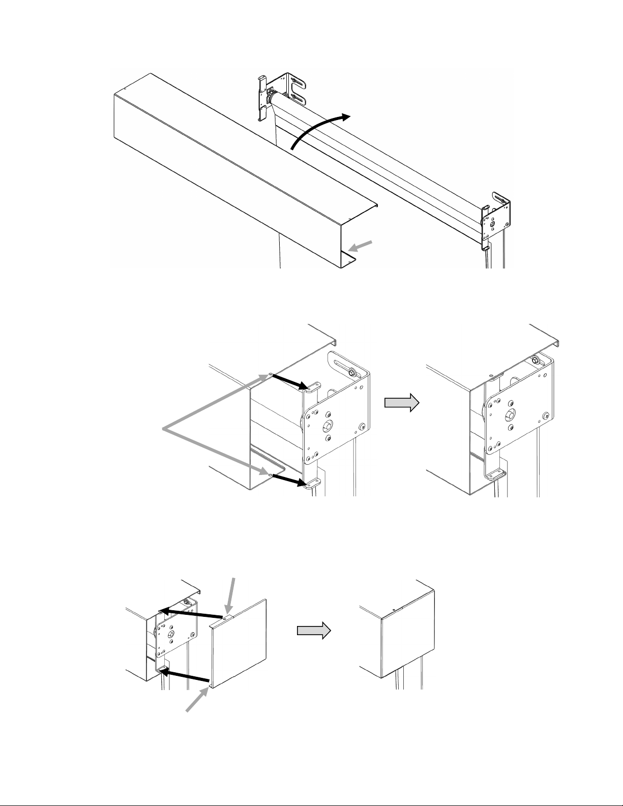
5) Place the Fascia over the top of the Shade.
6) Align the Fascia Mounting Holes with the matching holes on the legs of the Wall Brackets
(both sides).
7) Add the End Covers by sliding them over the Wall Brackets but beneath the Fascia such that
the mounting holes align with the Fascia mounting hole and the End Cover Tabs are tucked
beneath the Fascia.
Place Fascia Over the
Top of the Roll Good
This Fascia
Edge Will Go
Up Against
Roll Good
Fascia
Mounting
Holes
End Cover Tab
End Cover Tab

16
8) Drive two 8-32x5/8” Pan Head screws on the top side (one per side) to secure the Fascia
and End Covers to the Wall Brackets.
9) Drive two more screws on the bottom side (one per side) to secure the Fascia and End
Covers to the Wall Brackets.
10) Test the product once again, making sure that it goes all the way up and down.
Top Screws
Bottom Screws

17
6. Installation Certification
In order for the installation to be certified, photograph the following area of the installation of each
window and submit them to the Ballistic Barrier sales contact.
1. At least four pictures total that will include:
a. Picture of the mounting of the window cover in the deployed position. Capture the
entire window and the mounted assembly.
b. Picture of the mounting of the window cover in the retracted position.
c. A close-up of the right-side Hem Bar Lock, as it is mounted to the wall.
d. Repeat for the left-side Hem Bar Lock.
e. If the Hem Bar Lock assemblies were omitted, an oral or written statement from
the customer must be noted, and then a WRITTEN statement from the installer to
BBP that the customer approved the installation omission.
2. Photos of any modifications, even if they are approved by Ballistic Barrier.
3. Photos or video of any element of the product that causes you concern.
7. Warranty and Limit of Liability Information
Ballistic Barrier Products, Inc. ("BBP," "we," "us" or "our") provides access to this product
(collectively, "Products") to you ("you" or "your"), subject to the following Terms of Use and
Conditions of Sale (collectively, the "Terms and Conditions") with the following limited warranty
and limit of liability, which may be revised and updated by us from time to time, with or without
notice to you. For the most up-to-date and comprehensive terms and conditions of this sale, visit
www.ballistic-barrier.com/warranty.
Limited warranty
BBP warrants that all product is sold new.
Fabricated parts will meet physical dimensions that are based on the customer-supplied
dimensions for any window or door that is intended to be protected by the product. For any
object, material, or ingress/egress that is intended to be protected by the product that does not fit
a generally acceptable definition of a window or door, BBP must agree upon warranty coverage for
said item in writing for these terms and conditions of sale to be applicable. Without expressed
consent for coverage, use of the products is deemed as unintended, and all warranties, both
express and implied are void.
Installation of the product will be performed in accordance with generally acceptable industry
standards. You agree to inspect all installation work performed by BBP within three (3) business
days from the date of installation. If any installation services are determined not to conform to
industry standards, then BBP shall, at its option, either re-install the material or refund the cost of
such installation services.
Installation services provided by BBP will be defect-free for a period of one year from the date of
the delivery of the original sale.
Installation services provided by a BBP partner will be covered in accordance with the warranty
provided by said affiliate.
If the product fails to conform to the specified warranty, BBP, at its option, will determine if onsite
repair or a replacement is best suited for a solution.

18
BBP shall assign to you any vendor/warranties and/or remedies provided to BBP by its vendor to
the extent permitted by BBP's vendors/manufacturers.
You agree not to return the products until BBP agrees that you may do so.
All warranties will be void after the product has undergone a shooting event that exceeds the bullet
caliber, velocity, angle of fire, or quantity of impacts that it was certified to resist.
In a failure to meet the certified standard in a shooting event, BBP's liability will be limited to a
maximum value that will not exceed the cost of the original sale of the product to you.
Some jurisdictions may not allow the exclusion of certain types of warranties, including, without
limitation, implied warranties. As a result, the above limitation or exclusion may not apply to you.
The mechanical aspects of the product are warranted to be free of material or workmanship
defects for a period of one year from the date of initial purchase. This warranty includes the cost
of repairing or replacing materials (at BBP's discretion) and any shipping costs involved. Outside of
this, the cost of repairs will be handled on a case-by-case basis.
The product is guaranteed to function, in its ability to resist impacts from handgun fire that are in
accordance with the product's certification, for a period of seven (7) years. In a failure to meet this
guarantee, BBP will repair onsite, replace, or refund the cost at its discretion.
See also any applicable Conditions of Sale at www.ballistic-barrier.com/warranty for any other
conditional warranty information related to specific Product sales.
Limitation of Liability
To the fullest extent permitted by law, in no event and under no theory of liability, including
contract, tort, negligence, strict liability, warranty, or otherwise, will the BBP entities be liable to
you or to any other person or entity for any indirect, consequential, exemplary, incidental, special,
or punitive damages, or lost profits arising from or relating to these terms of use or your use of the
products.
Access to, and use of, the products is at your own discretion and risk, and you will be solely
responsible for any damage or injuries resulting in the product failing to perform outside the
standards to which it is certified.
In no event will the aggregate liability of the BBP entities exceed one hundred U.S. dollars ($100).
The limitations of this section will apply to any theory of liability, including those based on
warranty, contract, statute, tort (including negligence), or otherwise, and even if the BBP entities
have been advised of the possibility of any such damage, and even if any remedy set forth herein is
found to have failed its essential purpose.
The foregoing does not affect any liability that cannot be excluded or limited under applicable law.
If you are dissatisfied with the products, or with the terms of use, your sole and exclusive remedy is
to discontinue using the products.
Any cause of action against BBP with respect to the products must be instituted within one (1) year
from the date on which the claim arose.
See the Conditions of Sale at www.ballistic-barrier.com/warranty for all other limitations of liability
information related to Products.
Table of contents
Popular Indoor Furnishing manuals by other brands

Furniture of America
Furniture of America CM6314SF Assembly instructions

Godrej
Godrej CREST DIGITAL user manual

ofichairs
ofichairs Cube How to Adjust

THB
THB Wardrobe Absolut Plus 7 Doors Assembly instructions

OAKWORKS MEDICAL PRODUCTS
OAKWORKS MEDICAL PRODUCTS Powerline Series user manual

Baumax
Baumax DALIA 50 Assembly instructions

LPD Furniture
LPD Furniture STOCKHOLM 1 DRAWER BEDSIDE CABINET Assembly instructions

Guthrie Douglas
Guthrie Douglas Tess 100 installation manual

Lightolier
Lightolier CTS3-11 specification

Allen + Roth
Allen + Roth WSWS-SS1621-1C manual

Threshold
Threshold Cambridge T71113-4A Assembly instructions

NOVIGAMI
NOVIGAMI LENI Assembly & user instructions


