BBV Tx1000 MK2 Series User manual

Building Block Video Ltd.,
17 Apex Park,
Diplocks Industrial Estate,
Hailsham, East Sussex, BN27 3JU, UK.
Tel:+44 (0)1323 842727
Fax:+44 (0)1323 842728
Support:+44(0)1323 444600
www.bbvcctv.com
Tx300-400-1000MK2-1000 Keypad-Ex4 MK2-TxLD Installation Guide 12Jan05.doc
Telemetry
Transmitter
Installation
Guide
BBV
Models covered
Tx300
Page 3 (Simple, 1-2-1 controller)
Tx400 & Tx400DC
Page 7 (1-2-1 controller)
Tx1000 series MK2
Page 14 (8/16 camera matrix)
Tx1000 Keypad
Page 27 (Telemetry control keyboard for Tx1000 matrix)
Ex4 MK2
Page 28 (System expander – control 4 TX1000 from 1 keyboard)
TxLD MK2
Page 32 (RS232-RS422 converter)

IMPORTANT
Please read the following points before servicing or installing.
Pre-installation Checks - It is recommended that the unit be bench-tested prior to installation on the site.
Safety During Installation or Servicing - Particular care should be taken to isolate the pan/tilt head in
order to prevent operation while engineering work is being carried out. In addition any ladder or other
means of working on the receiver MUST NOT rest on the pan/tilt head as it is possible for the head to move
when not expected.
Safety Check - Upon completion of any service or repairs to the unit, safety checks should be performed to
ensure that the unit is in proper operating condition.
Co-ax Grounding - If an outside cable system is connected to the unit, be sure the cable system is
grounded.
Adhere to Safety Standards - All normal safety precautions as laid down by British Standards and the
Health and Safety at Work Act should be observed.
WARNING - TO PREVENT DANGER OF FIRE OR SHOCK, DO NOT EXPOSE THE INTERNAL
COMPONENTS OF THIS EQUIPMENT TO RAIN OR MOISTURE.
Damage Requiring Service - Servicing by qualified personnel should be carried out under the following
conditions:
(a) When the power-supply cord or plug is damaged;
(b) If liquid has been spilled, or objects have fallen into, the unit;
(c) If the internal electronics of the unit have been exposed to rain or water;
(d) If the unit does not operate normally by following the operating instructions. Adjust only those
controls that are covered by the operating instructions, as improper adjustment of other controls may
result in damage and will often require extensive work by a qualified technician to restore the unit to
normal operation;
(e) If the unit has been dropped or the enclosure is damaged;
(f) If the unit exhibits a distinct change in performance. This indicates a need for service.
Replacement Parts - If replacement parts are required, ensure that only replacement parts recommended
by the product manufacturer are used.
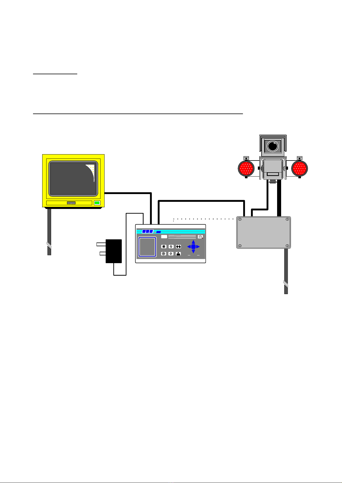
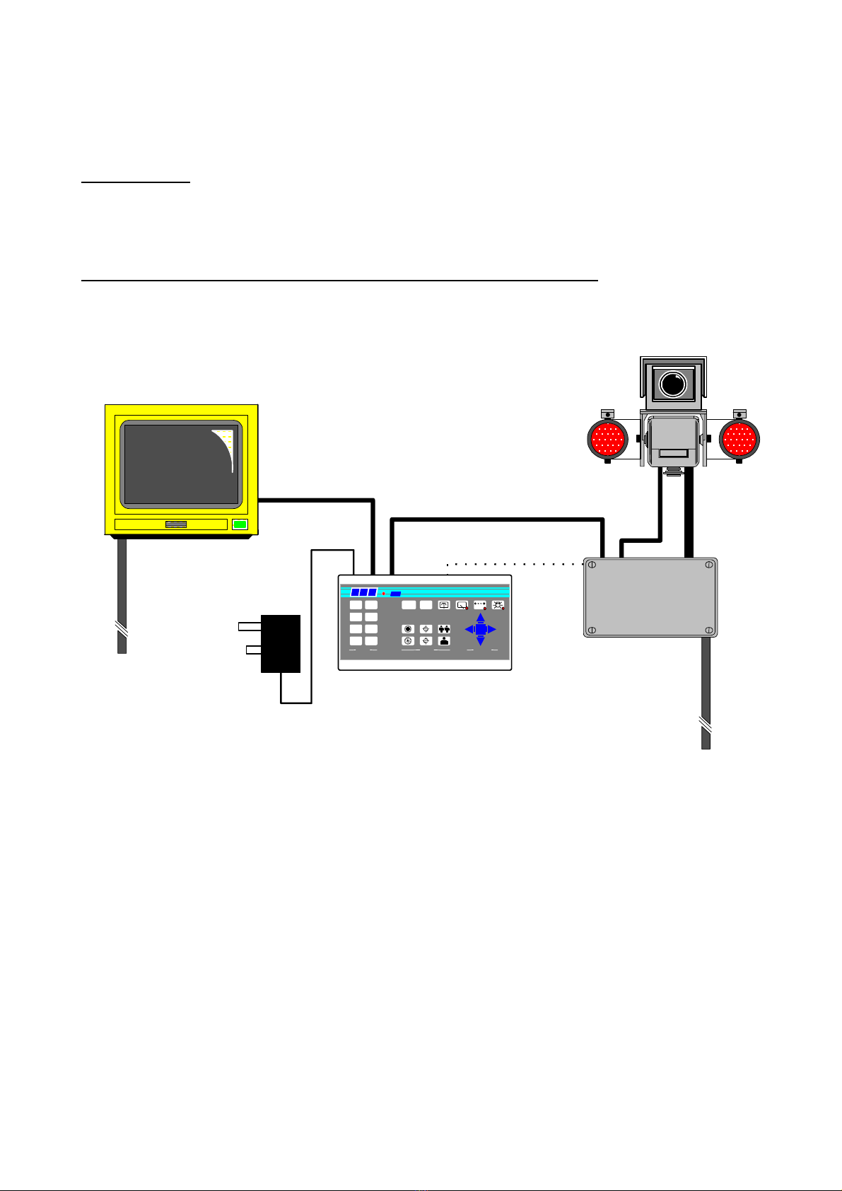
Additional information
It is strongly recommended that this equipment is pre-
built in the installer's workshop in advance, to ensure
problem-free installation at the customer's premises.

Tx300-400-1000MK2-1000 Keypad-Ex4 MK2-TxLD Installation Guide 12Jan05.doc
Tx300 (simple 1-2-1 controller) Page 3
Tx300Simple 1-2-1 controller
INTRODUCTION
The BBV Tx300 is a very easy-to-use keypad for use in a single-camera CCTV system. It is easily installed
into either a new or an existing system simply by connecting a BNC input and output, or twisted wire pair
and a 9Vdc supply.
ILLUSTRATION OF TELEMETRY SYSTEM SHOWING LOCATION OF KEYPAD
POWE
IRIS FOCUS ZOOM
PAN+ TILT
PROGR AM
B B V 1000
Tx300 Transmitter
BBV Rx receiver
9v PSU
75R Terminated
Monitor
POWE
Basic One-to-One Telemetry System
250M-RG59/ 500M-CT125
alternative-20mA twisted pair

Tx300-400-1000MK2-1000 Keypad-Ex4 MK2-TxLD Installation Guide 12Jan05.doc
Tx300 (simple 1-2-1 controller) Page 4
LAYOUT OF THE BBV Tx300 KEYPAD
KEYPAD FUNCTIONS
Pan and Tilt Action:
Press the relevant direction arrow(s)

Tx300-400-1000MK2-1000 Keypad-Ex4 MK2-TxLD Installation Guide 12Jan05.doc
Tx300 (simple 1-2-1 controller) Page 5
Lens Action
There are six lens-function switches on the BBV Tx300 keypad. These
are Iris Open, Iris Close, Focus Near, Focus Far, Zoom In and Zoom Out.
Press and hold the relevant key until the desired picture is obtained.
Note: If the key is pressed and held for longer than one second, High
Speed Lens Action is activated. Inching is achieved by quick presses of
the key.
Auxiliary Function Switch
There is only one auxiliary function switch on the Tx300; it is designated as the lights relay, press for on,
press for off.
SELF TEST
To run Self-Test, press Program and Focus Far. This activates the Self-Test routine in the BBV range of Rx
telemetry receivers. See the Telemetry Receiver Installation Handbook for more details.
IRIS LEVEL PROGRAM
To pre-set the aperture of the iris, press Iris Open or Iris Close until the desired level is reached, then press
Program and iris open together to set. Note: There is a 15-second time-out, after reaching the correct
aperture setting, in which to program the Iris setting. When this time period expires, the iris reverts to its
default setting.
IRIS SET AND
LIGHTS CONTROL

Tx300-400-1000MK2-1000 Keypad-Ex4 MK2-TxLD Installation Guide 12Jan05.doc
Tx300 (simple 1-2-1 controller) Page 6
RANDOM PAN – Rx300
The Rx300 telemetry receivers provide a random pan feature. During Random Pan operation, the camera is
randomly panned left or right for a random duration, paused for a random duration and then panned again.
This adds the affect that the camera is manually controlled. During random pan, the camera can be tilted to
the desired angle using the up/down buttons. Random pan is disabled by pressing either the pan right or
the pan left button.
TWISTED PAIR OUTPUT
The TWISTED PAIR output sends telemetry signals from the transmitter to the receiver. A video cable
connection is still required. The normal reason for using a twisted pair option is to connect to a non-cable
transmission system, fibre, microwave etc.
The twisted pair output option provides a 20mA compatible output. 1200 baud 8 data bits 1 stop bit, Even
parity.
V
BB
12
34
56
78
IRIS FOCUS ZOOM
PRESETS LENS PAN &
TILT
PROGRAM AUTOPAN
#
Polarity not important at Rx.
Maximum cable resistance 330R
If RF/Laser/Microwaveetc. used
to extend link, 20mA input may
bepolaritysensitive.
Grey connector on Rx PCB, Pins 1 &
2
Section of Rx
Sim
p
le twisted
p
air telemetr
y
when not
p
ractical to use u
p
-
A
coaxial cable is required to carry the video from the camera to the control
If the Rx is over driven from the RF/
Laser/Microwave equipment, the error
LED will light. Connecting a 470R
resistor across Pin 1/2 cures
bl
Tx300/400/400DC

Tx300-400-1000MK2-1000 Keypad-Ex4 MK2-TxLD Installation Guide 12Jan05.doc
Tx400 (1-2-1 controller) Page 7
Tx4001-2-1 controller
INTRODUCTION
The BBV Tx400 is a very easy-to-use keypad for use in a single-camera CCTV system. It is easily installed
into either a new or an existing system simply by connecting a BNC input and output, or twisted wire pair
and a 9-volt supply.
ILLUSTRATION OF TELEMETRY SYSTEM SHOWING LOCATION OF KEYPAD
POWE Tx400 Transmitter
BBV Rx receiver
9v PSU
75R Terminated
Monitor
POWE
Basic One-to-One Telemetry System
B B V
PRESETS
87
5 6
43
1 2
LENS
IRIS FOCUS ZOOM
PROGR AM #
400
A
UTOPAN
PAN+ TILT
250M-RG59/ 500M-
CT125
alternative-20mA twisted pair

Tx300-400-1000MK2-1000 Keypad-Ex4 MK2-TxLD Installation Guide 12Jan05.doc
Tx400 (1-2-1 controller) Page 8
LAYOUT OF THE BBV Tx400 KEYPAD
KEYPAD FUNCTIONS
Pan and Tilt Action:
Press the relevant direction arrow(s)
Lens Action
There are six lens-function switches on the BBV Tx400
keypad. These are IRIS OPEN, IRIS CLOSE, FOCUS
NEAR, FOCUS FAR, ZOOM IN and ZOOM OUT.
Press and hold the relevant key until the desired
picture is obtained. Note: If the key is pressed and
held for longer than one second, High Speed Lens
Action is activated. Inching is achieved by quick
presses of the key.

Tx300-400-1000MK2-1000 Keypad-Ex4 MK2-TxLD Installation Guide 12Jan05.doc
Tx400 (1-2-1 controller) Page 9
Auxiliary Function Switches
There are four auxiliary function switches on the BBV Tx400 keypad. These are Wash, Wipe, Autopan and
Lights.
Their functions are as follows:
WASH - Press and hold for washer motor to run.
WIPE - Latching output, press on/press off.
AUTOPAN - Press, LED lights up and the Autopan motor starts. Pressing Left or Right stops
Autopan.
LIGHTS - Latching output, press on/press off.
SELF TEST
To run Self-Test, press and hold PROGRAM whilst pressing WASH. This activates the Self-Test routine in
the BBV range of Rx receivers. See the Rx Series Telemetry Receiver Installation Handbook for more
details.
IRIS LEVEL PROGRAM
To pre-set the aperture of the iris, press IRIS OPEN or IRIS CLOSE until the desired level is reached, then
press and how PROGRAM whilst pressing WIPE to set. Note: There is a 15-second time-out, after
reaching the correct aperture setting, in which to program the Iris setting. When this time period expires, the
iris reverts to its default setting.

Tx300-400-1000MK2-1000 Keypad-Ex4 MK2-TxLD Installation Guide 12Jan05.doc
Tx400 (1-2-1 controller) Page 10
The remainder of this manual refers to features found only on the receivers supporting presets,
Rx100 dome interface, Rx400P AC preset receiver, Rx400DC high/variable speed DC receiver and
RX45X, RX55X advanced receivers.
PRESETS
To select a pre-programmed pre-set, press one of the Pre-set keys 1to 8.
To programme a pre-set, first position the camera using UP/DOWN and LEFT/RIGHT arrows. Then set
Zoom and Focus. When satisfied with the position and the quality of the picture, press and hold PROGRAM
whilst pressing one of the Pre-set keys 1 to 8.
To erase a pre-set, press and hold PROGRAM whilst pressing IRIS OPEN. (Note: This will erase the last-
selected pre-set.) For example, to erase Pre-set 4, press pre-set key 4, then press and hold PROGRAM
whilst pressing IRIS OPEN.
PATROL SETTINGS
A Patrol is a succession of pre-sets strung together by delays between them, the receiver continues in this
mode until a pan or tilt key is pressed.
Each Rx preset receiver is capable of operating two patrol modes made up of the 16 pre-sets. The
Tx400/400DC will control the first 8 presets. When a pre-set is programmed it is automatically entered into
both patrols, the user/installer has to remove a pre-set from either or both patrols if he so wishes.

Tx300-400-1000MK2-1000 Keypad-Ex4 MK2-TxLD Installation Guide 12Jan05.doc
Tx400 (1-2-1 controller) Page 11
STARTING THE PATROLS
On starting a patrol the receiver will immediately move to the first programmed included pre-set.
To start patrol 1 - Press and hold PROGRAM whilst pressing AUTOPAN.
To start patrol 2 - Press and hold PROGRAM whilst pressing LIGHTS.
Their function is to enable a string of presets to be selected in turn, switching between presets after a fixed
period of time (nominally 30 seconds).
Note: Once the nominal time period of 30 seconds has been altered, it cannot be recovered.
These patrols can be stopped at any time by pressing LEFT,RIGHT,UP or DOWN.
TO PROGRAM A PATROL
There is no separate Patrol programming function with the BBV Tx400 keypad. Once a pre-set has been
programmed, it is automatically included in Patrols 1 and 2.
TO REMOVE A PRESET FROM A PATROL
1. First select and goto the pre-set concerned by pressing the appropriate Pre-set key (keys 1 to 8)
2. Press and hold PROGRAM whilst pressing FOCUS NEAR for Patrol 1 - TOP ROW
or Press and hold PROGRAM whilst pressing FOCUS FAR for Patrol 2 - BOTTOM ROW

Tx300-400-1000MK2-1000 Keypad-Ex4 MK2-TxLD Installation Guide 12Jan05.doc
Tx400 (1-2-1 controller) Page 12
TO PROGRAM THE PATROL DELAY
First, determine the time delay required from the table below:
Pre-set Key 1 - Random switching from 0 to 100 seconds
Pre-set Key 2 - 12 Seconds switching
Pre-set Key 3 - 24 Seconds switching
Pre-set Key 4 - 36 Seconds switching
Pre-set Key 5 - 48 Seconds switching
Pre-set Key 6 - 60 Seconds switching
Pre-set Key 7 - 72 Seconds switching
Pre-ser Key 8 - 84 Seconds switching
Press and release the pre-set key that corresponds with the delay desired, then press and hold
PROGRAM whilst pressing ZOOM OUT to set patrol 1 delay
Or
PROGRAM whilst pressing ZOOM IN to set patrol 2 delay
SPARE OUTPUTS
Depending on the receiver the spare output is used to provide additional outputs or used for advanced
features with the Rx100 and RX45X/55X range. To activate, press and hold #whilst pressing pre-set key
1,2,3 or 4.

Tx300-400-1000MK2-1000 Keypad-Ex4 MK2-TxLD Installation Guide 12Jan05.doc
Tx400 (1-2-1 controller) Page 13
TWISTED PAIR OUTPUT
The TWISTED PAIR output sends telemetry signals from the transmitter to the receiver. A video cable
connection is still required. The normal reason for using a twisted pair option is to connect to a non-cable
transmission system, fibre, microwave etc.
The twisted pair output option provides a 20mA compatible output. 1200 baud 8 data bits 1 stop bit, Even
parity.
V
BB
12
34
56
78
IRIS FOCUS ZOOM
PRESETS LENS PAN
&
TILT
PROGRAM AUTOPAN
#
Polarity not important at Rx.
Maximum cable resistance 330R
If RF/Laser/Microwave etc. used
to extend link, 20mA input may
be polarity sensitive.
Grey connector on Rx PCB, Pins 1 & 2
Section of Rx
Simple twisted pair telemetry when not practical to use up-the-coax telemetry.
A coaxial cable is required to carry the video from the camera to the control point.
If the Rx is over driven from the RF/
Laser/Microwave equipment, the error
LED will light. Connecting a 470R
resistor across Pin 1/2 cures problem.
Tx300/400/400DC

Tx300-400-1000MK2-1000 Keypad-Ex4 MK2-TxLD Installation Guide 12Jan05.doc
Tx1000 MK2 (8/16 camera controller) Page 14
Tx1000 MK2
The system is available in four main variants:
1. TX1000/8 MK2 8 camera inputs and 2 monitor outputs.
2. TX1000/16 MK2 16 camera inputs and 2 monitor outputs.
3. TX1000/8A MK2 8 camera inputs, 2 monitor outputs and 16 alarm inputs.
4. TX1000/16A MK2 16 camera inputs, 2 monitor outputs and 16 alarm inputs.
Options are available to allow control of 64 cameras using single keyboard and an EX-4 MK2 keyboard
expander. Please contact BBV for further information.
All variants allow the use of two fully independent keypads.
The transmitter is a two-part design: the base unit, which is wall- or rack-mounting; and the keypad which is
connected by a video cable and a bi-directional RS232 link running at 9600 baud, No parity, 8 data bits and
1 stop bit.
INTRODUCTION
The BBV Tx1000 MK2 Series transmitters are very simple to use in multi-camera CCTV systems. They are
easily installed into either a new or an existing system.
Up-the-coax telemetry allows upgrading of static cameras to PTZ without the need for additional cabling.
BBV RS422 telemetry is available as standard where up-the-coax telemetry is not suitable on not required
and in addition an optional 20mA twisted pair unit can be retro fitted to the TX1000 Mk2 for complete
compatibility with existing TX1000 sites.

Tx300-400-1000MK2-1000 Keypad-Ex4 MK2-TxLD Installation Guide 12Jan05.doc
Tx1000 MK2 (8/16 camera controller) Page 15
Rx100
domecamera
4 local alarms
STATIC
static camera Rx200
static camera with
lights/wash/wipe Rx200
simple AC panner
Rx300
AC P/T Zoom/Focus
1 Aux.
Rx400DC
High & Variable speed
P/T Zoom/Focus
16 Preset with 3 Aux.
8 Local alarms
TX1000 base unit
TxLD
Tx1000 is compatible with numerous 3rd party equipment including:
DM DVST (with BBV PL1), Sony PMS, SiComTeleEye, BischkeFSC, Tecton
DRAX (with Tecton 300KB), Vision Systems Adpro VST10CA, Vision Research
RapidVision, Contex ReCam, Pinacl, Imigix, ControlWare, DigiEye, Mitsubishi
DS150.
Compatible with BBV Pick-A-Point graphical user interface.
Majority of other brand front ends have drivers available.
Up-The-Coax telemetry control up to 500M CT125 / 250M RG59
RS232 control Max distance - 50M
Optional TxLD available upto 1200M
Baud rate: 9600,N,8,1
video out
BBV TX1000 mk2 telemetry system
alarm cable or
Security Enclosures'
Videswitch can be used to
transmit alarm contact over
coax
Dome library includes:
360 Vision dome
Borsatec BT270/271FF
Chugai/Computar SMD
Daiwa DMP16-H3
Dennard type 2050/55/60
Ulltrak/Diamond KD6
Dynacolor 7720
Forward Vision MIC1-300
Gardiner Security Juno
*JVC TK-C675BE/676
Kalatel Cyberdome (1/1/02)
LiLin PIH717X/7000/7600/7625
MarkMercer D250MPT
Panasonic WV-CSR400/600/650
Panasonic WV-CS850
*Pelco SD5 'Spectra'
Philips Autodome (RS232)
Samsung SCC641/643
Sanyo VCC9200P
Sensormatic Speed dome (RS422)
Sony EVI-31D/1000
Star MD100 & MD200
VCL TP domes
Vicon Surveyor 2000
Vista Powerdome
*Rx100/24/ includes 24Vac 100VA
PSU. Call BBV for info. 9Vdc
PSU
Optional TxLD (RS422) link.
Distance 1200M max.
Twin Twisted Pair
video & data
All BBV Rx receivers feature built-in launch
amplifier with Gain & Lift controls. Telemetry
control via Coax or 20mA twisted pair.
230Vac/110Vac/24Vac options.
BBV coaxial receivers can
also be controlled using
models from DM's mux
range, Tecton Darlex,
Adpro FastTrace, Sanyo
DVR.
Vision Factory Cameo can
drive receivers via 20mA
telemetry via a TIF unit.
OPTIONAL SLAVE KEYBOARDKEYBOARD
TxLD
Optional TX/TPO MK2 20mA output
Rx400P
AC P/T Zoom/Focus
16 Presets with 4 Aux.
alarm cable
Rx45X(AC)
Rx55X(DC)
P/T Zoom/Focus/Iris
32 Preset with 3 or 4 Aux.
8 Local alarms
BBV Up-The-Coax and
RS422 telemetry
BBV RS422 telemetry - 1200M max
9Vdc
PSU
9Vdc
PSU
Optional Star Wired
20mA Telemetry.
Cable closed loop
resistance < 300R

Tx300-400-1000MK2-1000 Keypad-Ex4 MK2-TxLD Installation Guide 12Jan05.doc
Tx1000 MK2 (8/16 camera controller) Page 16
LAYOUT OF THE BBV Tx1000 KEYPAD
Connections
Having mounted the base unit on the wall or in a rack, continue as follows:
1. Connect the keypad to 9-pin D socket marked "Keypad 1".
2. Connect a BNC cable from output M1 to the keypad, and connect the other keypad connection to the
video monitor’s video input. Make sure that the monitor is terminated not Hi-Z.
3. If the keypad is remotely sited from the base unit, connect the 9Vdc plug-mounted power supply to the
keypad via the 2.1mm power connector.
4. Connect either a second video monitor (no keypad and no text), or the second keypad to Output 2.
Note that even if both keypads are local to the main unit, the second keypad must be powered from it’s
own 9Vdc power supply.
5. Connect the BNC cables from the cameras/receivers to the upper BNC sockets in each row, marked
"VIDEO IN".
6. Connect any other equipment requiring the camera video signals to the lower BNC sockets marked
"LOOP OUT". Note that the action of connecting to the video-out socket removes the 75Ωtermination.
7. If the user relay terminals are being used, connect these to the LOW VOLTAGE equipment of your
choice.
PIN 6
PIN 7
PIN 8
Normally closed
Common
Normally open
8. Plug in the matrix 9Vdc power supply. The STATUS LED should flash and the monitors should show
the video from Camera 1.

Tx300-400-1000MK2-1000 Keypad-Ex4 MK2-TxLD Installation Guide 12Jan05.doc
Tx1000 MK2 (8/16 camera controller) Page 17
CAMERA SELECTION
A camera may be selected onto the controlled monitor by pressing the relevant numbered camera key, 1-16.
MONITOR SELECTION
The monitor key has a red LED, which is lit when the keypad is controlling the second monitor output.
Pressing the monitor key toggles between controlling monitor 1 and monitor 2.
SEQUENCE ACTIVATION
Pressing the sequence key will start the camera sequence on the currently selected monitor. The on-screen
display changes from CAM XX to SEQ XX to indicate that the sequence is running. To stop the sequence,
select a camera on the main monitor.
PROGRAMMING THE SEQUENCE
Holding down the sequence key causes the sequence to run through the list of cameras at the rate of one
per second, allowing the operator to quickly determine which cameras are being sequenced. While the
sequence key is held down, any camera key pressed will toggle the inclusion or exclusion of the relevant
camera. When delivered, all camera inputs are included in the sequence.
ALTERING THE SEQUENCE DELAY
This is achieved by pressing the Program key, to gain access to the menu. The sequence delay time may
be altered using Option 9. The on-screen prompt "Seq Delay" appears, inviting the operator to enter a
number from 1 to 16 for the following values:
1
2
3
4
5
6
7
8
9
10
11
12
13
14
15
16
5 seconds
10 seconds
15 seconds
20 seconds
25 seconds
30 seconds
35 seconds
40 seconds
45 seconds
50 seconds
55 seconds
60 seconds
65 seconds
70 seconds
75 seconds
80 seconds
After entering the delay value, the screen clears.
THE TRIANGLE/RELAY KEY
This key activates a relay in the base unit. Pressing the key causes triangle relay contacts to changeover;
releasing the key causes the contacts to revert to original position. This relay may be used by the installer to
activate a panic record facility on a VCR, or to activate a video printer, etc. These contacts are low-voltage,
low-current only.
IMPORTANT: DO NOT CONNECT THESE CONTACTS TO MAINS POTENTIALS

Tx300-400-1000MK2-1000 Keypad-Ex4 MK2-TxLD Installation Guide 12Jan05.doc
Tx1000 MK2 (8/16 camera controller) Page 18
KEYPAD FUNCTIONS
The keypads should not be connected or disconnected from a "live" working unit, as this may damage the
RS232 components.
Priority control between two keypad systems
Keypad one has priority over keypad two. If keypad one is only viewing but not operating any camera, then
keypad two may move that same camera. After movement commands on keypad one, there is a 20-second
or so lock-out period before control is given to keypad two.
Pan and Tilt Action:
Press the relevant direction arrow(s)
Lens Action
There are six lens-function switches on the BBV Tx400
keypad. These are Iris Open, Iris Close, Focus Near,
Focus Far, Zoom In and Zoom Out. Press and hold the
relevant key until the desired picture is obtained. Note:
If the key is pressed and held for longer than one
second, High Speed Lens Action is activated. Inching
is achieved by repeated quick presses of the key.
Auxiliary Function Switches
There are four auxiliary function switches on the BBV Tx1000 keypad. These are Wash, Wipe, Autopan and
Lights.
Their functions are as follows:
Wash - Press and hold for washer motor to run
Wipe - Latching output, press on/press off
Auto - Press, LED lights up and autopan motor starts. Pressing Left or Right stops Auto
Lights - Latching output, press on/press off

Tx300-400-1000MK2-1000 Keypad-Ex4 MK2-TxLD Installation Guide 12Jan05.doc
Tx1000 MK2 (8/16 camera controller) Page 19
SELF TEST
To activate the self test feature for any particular camera receiver, first select that receiver, then press the
Program button and select Menu Option 2. The screen text will clear and Self Test will be activated. See
the Rx Series Telemetry Receiver Installation Handbook for more details.
IRIS LEVEL PROGRAM
To preset the aperture of the iris, press Iris Open or Iris Close until the desired level is reached, then press
Program and Option 3. Note: There is a 15-second time-out, after reaching the correct aperture setting, in
which to program the iris setting. When this time period expires, the iris reverts to its default setting.

Tx300-400-1000MK2-1000 Keypad-Ex4 MK2-TxLD Installation Guide 12Jan05.doc
Tx1000 MK2 (8/16 camera controller) Page 20
The remainder of this manual refers to features found only on receivers that support
presets. (Rx100, Rx400P, Rx400DC, Rx45X, Rx55X).
PRESETS
To select a pre-programmed preset, press the Preset key. On the screen, "Preset" will appear. While
holding down the Preset key, select the desired preset number.
To programme a preset, first position the camera using the Up/Down and Left/Right arrows. Then set Zoom
and Focus. When satisfied with the position and the quality of the picture, press Program and select Option
1. When the on-screen display changes to "Program Preset", enter the number of the preset you wish to
program.
To erase a preset, press the Program key to gain access to the menu. Select Option 4 and when the
display changes to "Erase Preset", select the number of the preset to be erased.
PATROL SETTINGS
There are two patrol commands that can be started by the BBV Tx1000. They are activated by pressing the
Patrol key and either Key 1 or Key 2. All other keys are ignored. Their function is to enable a string of
presets to be selected in turn, switching between presets after a fixed period of time (nominally 30 seconds).
These patrols can be stopped at any time by pressing any of the four arrows on the Pan and Tilt control,
when the receiver on which patrol is running is selected.
To Programme a Patrol
There is no separate patrol-programming function with the BBV Tx1000 keypad. Once a preset has been
programmed, it is automatically included in Patrols 1 and 2.
To Remove a Preset from a Patrol
1. Select the receiver on which the patrol is to run.
This manual suits for next models
10
Table of contents