BD Sensors DM 10 User manual
www.bdsensors.com
DE
EN
Deutsch
Montageanleitung /
Mounting instructions
Digitalmanometer / Digital pressure gauge
DM 10
Zentrale
Headquarters
BD SENSORS GmbH
BD-Sensors-Str. 1
D - 95199 Thierstein
Deutschland / Germany
Tel.: +49 (0) 92 35 / 98 11-0
Fax: +49 (0) 92 35 / 98 11-11
Osteuropa /
Eastern Europe
BD SENSORS s.r.o.
Hradištská 817
CZ - 687 08 Buchlovice
Tschechische Republik /
Czech Republic
Tel.: +42 (0) 5 72 / 4 11-0 11
Fax: +42 (0) 5 72 / 4 11-4 97
Russland /
Russia
BD SENSORS RUS
39a, Varshavskoe shosse
RU - Moscow 117105
Russland /
Russia
Tel.: +7 (0) 9 59 81 / 09 63
Fax: +7 (0) 9 57 95 / 07 21
Diese Montageanleitung stellt einen Auszug
aus der ausführlichen Betriebsanleitung dar.
Bitte laden Sie sich diese auf unserer Home-
page herunter, falls Sie nicht mit dem Produkt
vertraut sind.
These mounting instructions are an excerpt from the complete
operating manual. It may be downloaded from our homepage, if
you are not familiar with the device.
http://www.bdsensors.de/produkte/download/anleitungen
http://www.bdsensors.com/products/download/manuals
– Technische Änderungen vorbehalten –
– Technical modifications reserved –
WARNUNG! Um Gefährdungen des Bedienpersonals und
Schäden am Gerät auszuschließen, müssen die beschrie-
benen Arbeiten von qualifiziertem Fachpersonal durchge-
führt werden.
WARNUNG! Halten Sie sich an Sicherheitshinweise und
Handlungsanweisungen, die in der Betriebsanleitung auf-
geführt werden. Zusätzlich sind die geltenden Unfallverhü-
tungsvorschriften, Sicherheitsbestimmungen sowie landes-
spezifische Installationsstandards und die anerkannten
Regeln der Technik einzuhalten.
Haftungsbeschränkung
Bei Nichtbeachtung der Betriebsanleitung, unsachgemäßer
Verwendung, Veränderung oder Beschädigung des Gerä-
tes übernimmt der Hersteller keine Haftung.
Bestimmungsgemäße Verwendung
Stellen Sie sicher, dass das Messmedium mit den medien-
berührten Teilen verträglich und das Gerät uneinge-
schränkt für die Anwendung geeignet ist. Die im aktuellen
Datenblatt aufgeführten technischen Daten sind verbindlich
und müssen unbedingt eingehalten werden.
Produktidentifikation
Batteriewechsel
Um die Batterien zu wechseln gehen Sie folgendermaßen
vor:
- Nehmen Sie die Abdeckung ab und wechseln Sie die
Batterie.
- Verschließen Sie anschließend das Gerät wieder
ordnungsgemäß.
Aufbau des Menüsystems
Montage
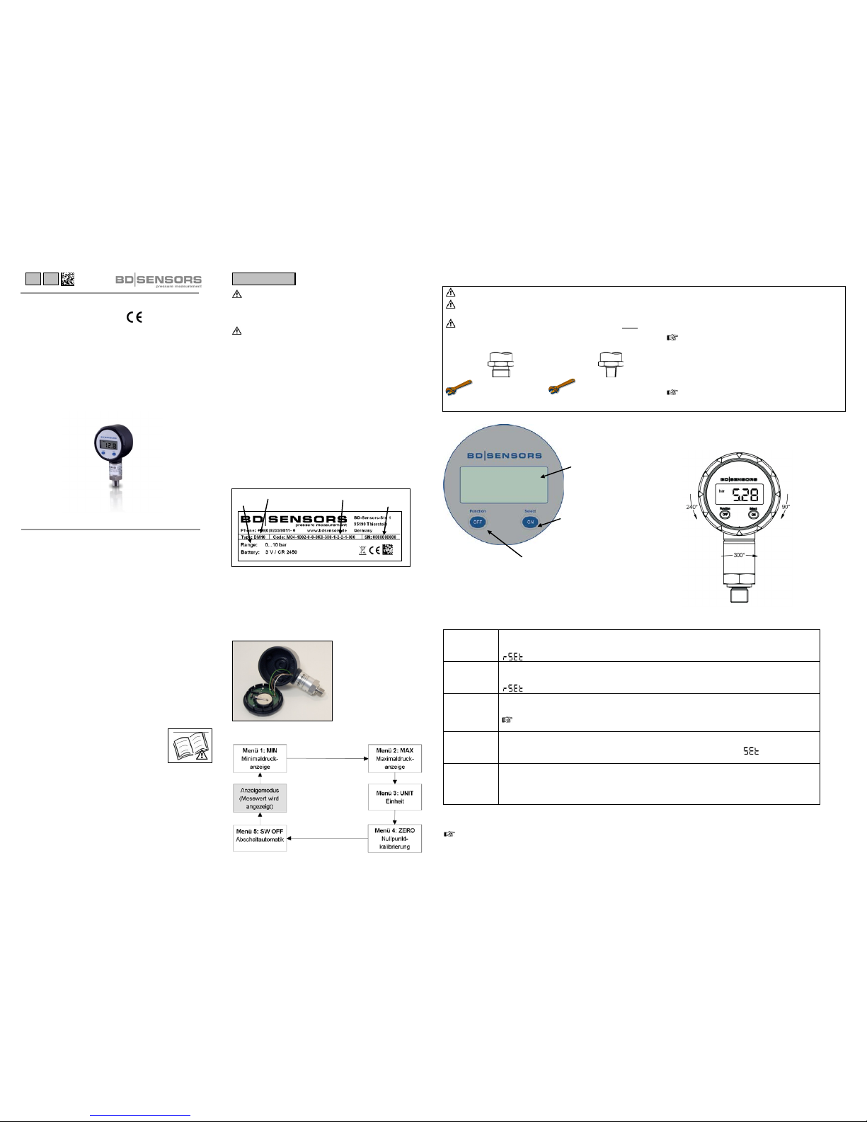
Anzeige- und Bedienmodul
Menüliste
Ausrichtung des Anzeigemoduls
Um eine einwandfreie Ablesbarkeit auch bei ungewöhnlichen
Einbaulagen zu gewährleisteten, kann die Anzeige in die
gewünschte Position gedreht werden.
Function / OFF -Taste
Select / ON -Taste
Display
Select / ON-Taste: Function / OFF-Taste:
- einschalten des Gerätes - ausschalten des Gerätes
- Auswahl der Druckeinheiten - "blättern" im Menüsystem
- Nullpunktkalibrierung
- Konfiguration der Abschaltautomatik
Bestellcode
Typenbezeichnung
Nenn-
druck
Serien-
nummer
1 MIN
Minimaldruckanzeige
Es wird der Minimaldruck, der während der Messung angelegen hat, in der Anzeige dargestellt.
Um den gespeicherten Wert zu löschen, drücken Sie die Select/ON-Taste. In der Anzeige erscheint
, der Wert wurde zurückgesetzt.
2 MAX
Maximaldruckanzeige
Es wird der Maximaldruck, der während der Messung angelegen hat, in der Anzeige dargestellt.
Um den gespeicherten Wert zu löschen, drücken Sie die Select/ON-Taste. In der Anzeige erscheint
, der Wert wurde zurückgesetzt.
3 UNIT
Einstellung der Druckeinheit
einstellbare Einheiten: bar, mbar, psi, MPa, mH2O
Mit der Select/ON-Taste wird die gewünschte Einheit angewählt und aktiviert.
Die mögliche Auswahl an Einheiten orientiert sich an der Genauigkeit des Gerätes und variiert in
Abhängigkeit vom Druckbereich.
4 ZERO
Nullpunkt
Stellen Sie bei dem ausgegebenen Wert in Bezug auf den Nullpunkt Abweichungen fest, können Sie die
Anzeige durch drücken der Select/ON-Taste neu kalibrieren. Im Display erscheint , der Wert wurde
zurückgesetzt. Bei einem vom Umgebungsdruck abweichenden Nullpunkt ist eine Druckreferenz nötig.
5 SW OFF
Konfiguration der Abschaltautomatik
Mit der Select/ON-Taste wird die gewünschte Abschaltautomatik ausgewählt.
Zuordnung der einstellbaren Ziffern:
"0": Abschaltautomatik ist ausgeschaltet
"1" – "5": Automatische Abschaltung nach 1 bis 5 Minuten
Das Menüsystem wird automatisch nach 10 Sek. verlassen, der zuletzt eingestellte Wert wurde gespeichert. Werden alle
Menüpunkte "durchblättert" wird nach
SW OFF
das Menüsystem verlassen.
Bei der Konfiguration der Einheit erfolgt eine Umrechnung des Messbereiches in die neue Einheit erst nach Verlassen des
Menüsystems. Je nach Druckbereich können nicht alle Einheiten verwendet werden.
WARNUNG! Montieren Sie das Gerät immer im druck- und stromlosen Zustand!
WARNUNG! Verwenden Sie zur Abdichtung eine geeignete Dichtung, entsprechend dem Messstoff und dem zu messenden
Druck. Für Anschlüsse nach DIN 3852 verwenden Sie
Verwenden SIE (bei Anschluss nach DIN 3852) KEIN
ZUSÄTZLICHES DICHTMATERIAL WIE WERG, HANF ODER
TEFLONBAND!
Anschluss nach DIN 3852 NPT-Anschluss
G1/4":ca. 5 Nm 1/4" NPT: ca. 30 Nm
Die angegebenen Anzugsmomente dürfen nicht überschritten werden!
Beachten Sie, dass durch die Montage keine unzu-
lässig hohen mechanischen Spannungen am
Druckanschluss auftreten, da diese zu einer Ver-
schiebung der Kennlinie oder zur Beschädigung füh-
ren könnten. Dies gilt ganz besonders für sehr kleine
Druckbereiche sowie für Geräte mit einem Druckan-
schluss aus Kunststoff.
Weitere wichtige Informationen entnehmen Sie bitte
der ausführlichen Bedienungsanleitung.

MA_DM10_070213
D
E
Englisch
www.bdsensors.com
Montageanleitung /
Mounting instructions
Digitalmanometer / Digital pressure gauge
DM 10
Zentrale
Headquarters
BD SENSORS GmbH
BD-Sensors-Str. 1
D - 95199 Thierstein
Deutschland / Germany
Tel.: +49 (0) 92 35 / 98 11-0
Fax: +49 (0) 92 35 / 98 11-11
Osteuropa /
Eastern Europe
BD SENSORS s.r.o.
Hradištská 817
CZ - 687 08 Buchlovice
Tschechische Republik /
Czech Republic
Tel.: +42 (0) 5 72 / 4 11-0 11
Fax: +42 (0) 5 72 / 4 11-4 97
Russland /
Russia
BD SENSORS RUS
39a, Varshavskoe shosse
RU - Moscow 117105
Russland /
Russia
Tel.: +7 (0) 9 59 81 / 09 63
Fax: +7 (0) 9 57 95 / 07 21
Diese Montageanleitung stellt einen Auszug
aus der ausführlichen Betriebsanleitung dar.
Bitte laden Sie sich diese auf unserer Home-
page herunter, falls Sie nicht mit dem Produkt
vertraut sind.
These mounting instructions are an excerpt from the complete
operating manual. It may be downloaded from our homepage, if
you are not familiar with the device.
http://www.bdsensors.de
http://www.bdsensors.com
– Technische Änderungen vorbehalten –
– Technical modifications reserved –
WARNING! In order to avoid hazards to operators and
damages to the device, the following instructions have to
be performed by qualified technical personnel.
WARNING! Adhere to the safety and operating instructions
stated in the operation manual. Effective regulations on oc-
cupational safety, accident prevention as well as national
installation standards and approved engineering tech-
niques must in addition be complied with.
Limitation of liability
If the instructions in the operating manual are not adhered
to or if the device is inappropriately used, modified or dam-
aged, liability is not assumed and warranty claims will be
excluded.
Intended use
Ensure that the medium is compatible with the media-
wetted parts and that the device is suitable for the applica-
tion without restrictions. The technical data listed in the cur-
rent data sheet is binding and must definitely be observed.
Product identification
Changing the batteries
To change the battery go ahead as follows:
- Remove the cap and change the battery.
- Lock the device after that properly.
Structure of the menu system
Mounting
Display and operating module
Structure of the menu system
Positioning of the display module
The display module of the pressure gauge is rotatable so that
clear readability is guaranteed even on unusual installation
positions.
Display
Select / ON -button
Function / OFF -button
Select / ON-button: Function / OFF-button:
- switch-on of the device - switch-off of the device
- choosing of the pressure units - scrolling in the menu system
- calibration of starting point
- configuration of the switch-off automatic
ordering code
type designation
input
serial
number
1 MIN
Minimum pressure display
The minimum pressure during the measurement process will be shown in the display.
To delete the stored value push the Select/ON-button. It appears in the display, the value has
been recessed.
2 MAX
Maximum pressure display
The maximum pressure during the measurement process will be shown in the display.
To delete the stored value push the Select/ON-button. It appears in the display, the value has
been recessed.
3 UNIT
Setting of the pressure unit
Possible units are: bar, mbar, psi, MPa, mH2O
The desired unit may be selected and activated with the Select/ON-button.
Depending on the nominal pressure range and the accuracy of the device, perhaps not all available
units could be used.
4 ZERO
Zero point
If you detect a shifting of the measured value deviating from the offset, the display can be re-calibrated via
pushing the Select/ON-button. The display shows , the value has been recessed. Differs the zero
point from the ambient pressure, it is a pressure reference necessary.
5 SW OFF
Configuration of the switch-off automatic
The desired switch-off automatic may be selected through the Select/ON-button.
Allocation of the programmable values:
"0": switch-off automatic is not active
"1" – "5": switch-off automatic after 1 up to 5 minutes
The menu system will be leaved automatically after 10 seconds, the last setted value has been saved. If you scroll all menu
points you will leave the menu system after
SW OFF
.
After configuring the unit, the conversion of the pressure range into the new unit will only occur after leaving the menu
system. Depending on the pressure range, probably not all available units can be used.
WARNING! Install the device only in depressurized and currentless state!
WARNING! Use a suitable seal, corresponding to the medium and the pressure input.
DO NOT USE ANY ADDITIONAL SEALING MATERIALS; LINKE YARN; HEMP OR TEFLON TAPE
(for connection acc. DIN 3852)!
Connection acc. to DIN 3852 NPT connections
G1/4":approx. 5 Nm 1/4" NPT: approx. 30 Nm
The indicated tightening torques must not be exceeded!
Take note that no inadmissibly high mechanical
stress occurs at the pressure port, since this
may cause a shifting of the characteristic curve
or to the demage. This is especially important
for very small pressure ranges as well as for
devices with a pressure port made of plastic.
For more information, please read the detailed
operating manual!
Table of contents
Languages:
Other BD Sensors Accessories manuals


Popular Accessories manuals by other brands


Vega
Vega vegacap 62 operating instructions

Hamron
Hamron 619-640 operating instructions

Oliver Kessler
Oliver Kessler SOLITAIRE PUNKAH Installation & owner's manual

Weir
Weir Synertrex S3-Gen1 installation guide

COMSOL
COMSOL PML20BK user manual

HomeMatic
HomeMatic HmIP-SWO-PR Installation instructions and operating manual


