BD Sensors DMK 457 User manual
www.bdsensors.com
EN
Operating Manual
Pressure Transmitter for Shipbuilding and Offshore
Applications
DMK 457, DMK 458 and DMP 457
Headquarters
BD SENSORS GmbH
BD-Sensors-Str. 1
D - 95199 Thierstein
Germany
Tel.: +49 (0) 9235-9811-0
Fax: +49 (0) 9235-9811-11
Eastern Europe
BD SENSORS s.r.o.
Hradištská 817
CZ - 687 08 Buchlovice
Czech Republic
Tel.: +42 (0) 572-4110 11
Fax: +42 (0) 572-4114 97
Russia
BD SENSORS RUS
39a, Varshavskoe shosse
RU - Moscow 117105
Russia
Tel.: +7 (0) 95-380 1683
Fax: +7 (0) 95-380 1681
China
BD SENSORS China Co, Ltd.
Room B, 2nd Floor, Building 10,
No. 1188 Lianhang Rd.
201112 Shanghai,
China
Tel.: +86 (0) 21-51600 190
Fax: +86 (0) 21-33600 613
further agencies in:
EUROPE
•Belgium
•Denmark
•Finland
•France
•Great Britain
•Greece
•Italy
•Lithuania
•Luxemburg
•Netherlands
•Norway
•Poland
•Portugal
•Romania
•Sweden
•Switzerland
•Slovakia
•Spain
•Turkey
•UK
•Ukraine
AFRICA
•Egypt
•South Africa
ASIA
•India
•Iran
•Israel
•Japan
•Kazakhstan
•Malaysia
•Singapore
•Taiwan
•Thailand
•Vietnam
AUSTRALIA
The addresses of our distribution partners are listed on our
homepage www.bdsensors.com. It is possible to download
data sheets, operating manuals, ordering codes and certifi-
cates, as well.
1. General information
1.1 Information on the operating manual
This operating manual contains important information on
proper usage of the device. Read this operating manual
carefully before installing and starting up the pressure
measuring device.
Adhere to the safety notes and operating instructions which
are given in the operating manual. Additionally applicable
regulations regarding occupational safety, accident preven-
tion as well as national installation standards and engineer-
ing rules must be complied with!
This operating manual is part of the device, must be kept
nearest its location, always accessible to all employees.
This operating manual is copyrighted. The contents of this
operating manual reflect the version available at the time of
printing. It has been issued to our best knowledge. BD
SENSORS is not liable for any incorrect statements and their
effects.
– Technical modifications reserved –
1.2 Symbols used
DANGER! – dangerous situation, which may result in
death or serious injuries
WARNING! – potentially dangerous situation, which
may result in death or serious injuries
CAUTION! – potentially dangerous situation, which may
result in minor injuries
!CAUTION! – potentially dangerous situation, which may
result in physical damage
NOTE – tips and information to ensure a failure-free
operation
1.3 Target group
WARNING! To avoid operator hazards and damages of
the device, the following instructions have to be worked
out by qualified technical personnel.
1.4 Limitation of liability
By non-observance of the operating manual, inappropriate
use, modification or damage, no liability is assumed and
warranty claims will be excluded.
1.5 Intended use
- Pressure transmitters DMK 456, DMK 457, DMK 458
and DMP 457 have been designed for typical applica-
tions in shipbuilding and offshore constructions. They
are suitable for measuring tasks with fluids and gases.
Typical applications of DMK 456 and DMK 458 are
pressure monitoring for loading and discharge proc-
esses as well as level measurement for ballast and
product storage tanks. Preferred areas of usage for
DMK 457 are gears, compressors, boilers, pneumatic
controls, elevators, oxygen applications and e.g. level
measurement into ballast tanks, etc. With mechanical
versions G1/2" open port or G1/2" flush DIN 3852 the
DMK 457 is especially suited for viscous, pasty or con-
taminated media due to the easily reachable ceramic
diaphragm. Preferred areas of usage for DMP 457 are
diesel engines, gears, compressors, pumps, boilers, hy-
draulic and pneumatic controls as well as elevators. The
pressure transmitters DMK 456, DMK 457, DMK 458
and DMP 457 fulfil the requirements of Germanischer
Lloyd (GL) as standard. DMK 457 as well as DMP 457
is additionally certificated by Det Norske Veritas (DNV).
The certificates are available for download on our
homepage: http://
www.bdsensors.com/proucts/download/certificates
- It is the operator's responsibility to check and verify the
suitability of the device for the intended application. If
any doubts remain, please contact our sales department
in order to ensure proper usage. BD SENSORS is not
liable for any incorrect selections and their effects!
- Permissible media are gases or liquids, which are com-
patible with the media wetted parts described in the data
sheet. In addition it has to be ensured, that this medium
is compatible with the media wetted parts.
- The technical data listed in the current data sheet are
engaging. If the data sheet is not available, please order
or download it from our homepage:
http://www.bdsensors.com
WARNING! Danger through improper usage!
1.6 Package contents
Please verify that all listed parts are undamaged included in
the delivery and check for consistency specified in your
order:
- pressure transmitter
- mounting instructions
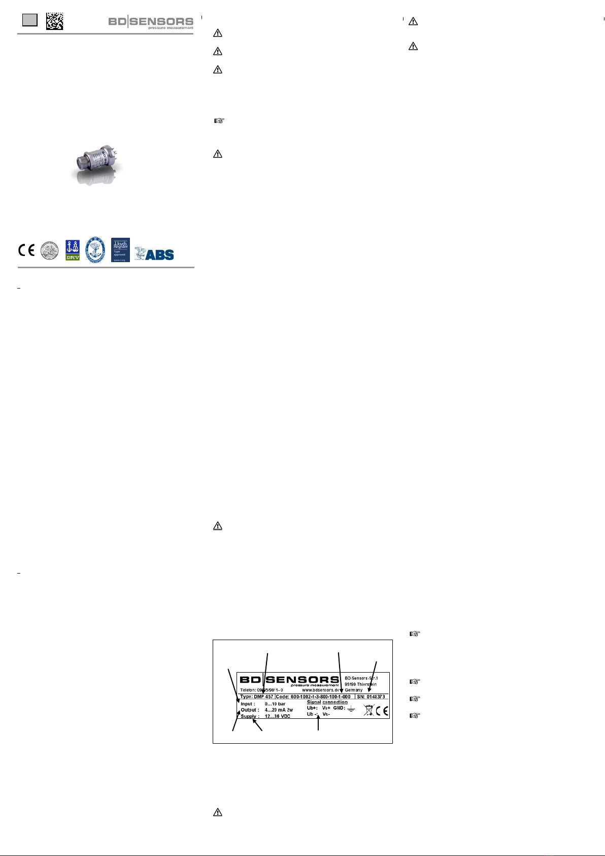
2. Product identification
The device can be identified by its manufacturing label. It
provides the most important data. By the ordering code the
product can be clearly identified.
Fig. 1 manufacturing label
!The manufacturing label must not be removed from the
device!
3. Mechanical installation
3.1 Mounting and safety instructions
WARNING! Install the device only when depressurized
and currentless!
WARNING! This device may only be installed by
qualified technical personnel who has read and under-
stood the operating manual!
DANGER! Explosion hazard, with devices for oxygen
applications, when used improperly. To ensure a usage
without danger, the following points must be adhered to:
- Make sure, your device has been ordered and de-
livered as a special version for oxygen applica-
tions. You can check the manufacturing label (see
figure 1). If the ordering code ends with "007", then
the device is suitable for oxygen applications.
- At time of delivery the device is packed into a plas-
tic bag in order to prevent it from impurity. Please
observe the indication label "Device for oxygen,
unpack only directly before assembling". Also,
avoid any skin contacts during unpacking and as-
sembly, in order to prevent greasy residues on the
device.
- During installation, the respective explosion protec-
tion regulations have to be met. Check, if ATEX-
approval is necessary for this type (oxygen) de-
vice. (the delivered device has no ATEX-approval)
- Note the entire design requirements meet the
standard demand of BAM (DIN 19247).
- Transmitters with o-rings of FKM Vi 567:
permissible maximum values: 15 bar/ 60° C.
!Handle this high-sensitive electronic precision
measuring device with care, both in packed and
unpacked condition!
!There are no modifications/changes to be made on the
device.
!Do not throw the package/device!
!To avoid damaging the diaphragm, remove packaging
and protective cap directly before starting assembly.
The delivered protective cap has to be stored!
!Place the protective cap on the pressure port again
immediately after disassembling.
!Handle the unprotected diaphragm very carefully - it is
very sensitive and may be easily damaged.
!Do not use any force when installing the device to
prevent damage of the device and the plant!
!For installations outdoor or in moist surroundings, the
following points have to be observed:
- To prevent moisture admission in the plug the de-
vice should be installed electrically after mounting,
at once. Otherwise a moisture admission has to be
blocked e.g. by using a suitable protection cap.
(The ingress protection in the data sheet is valid
for the connected device.)
- Choose an assembly position, which allows the
flow-off of splashed water and condensation. Avoid
permanent fluid at sealing surfaces!
- When using a cable gland device, turn the outgo-
ing cable downwards. If the cable has to be turned
upwards, then point it downward so the moisture
can drain.
- Install the device in such a way that it is protected
from direct solar irradiation. Direct solar irradiation
can lead to the permissible operating temperature
being overstepped in the worst case. Through this,
the operability of the device can be affected or
damaged. If the internal pressure increases due to
solar irradiation, temporary measurement errors
may occur.
!For devices with gauge reference in the housing (small
hole next to the electrical connection), install the device
in such a way, that the gauge reference is protected
from dirt and moisture. Should the device be exposed to
fluid admission, the functionality will be blocked by the
gauge reference. An exact measurement in this condi-
tion is not possible. Furthermore this can lead to dam-
ages on the device.
Take note that no inadmissibly high mechanical stress
occurs at the pressure port, since this may cause a
shifting of the characteristic curve or to the demage.
This is especially important for very small pressure
ranges as well as for devices with a pressure port made
of plastic.
In hydraulic systems, position the device in such a way
that the pressure port points upward (ventilation).
Provide a cooling line when using the device in steam
piping.
If there is any danger of damage by lightning or
overpressure when the device is installed outdoor, we
suggest putting a sufficiently dimensioned overpressure
protection between the supply or switch cabinet and the
device.
3.2 General installation steps
- Carefully remove the pressure measuring device from
the package and dispose of the package properly.
- Go ahead as detailed in the specific instructions below.
ordering code
connector pinout
type designation
supply
nominal
pressure
range
signal
serial
number
DMP 457
DMU Schiff_E_150915
3.3 Installation steps for DIN 3852
DO NOT
- Check to ensure the proper groove fitting of the o-ring
and additionally to ensure no damage to the o-ring.
USE ANY ADDITIONAL SEALING MATE-
RIALS, LIKE YARN, HEMP OR TEFLON TAPE!
- Ensure that the sealing surface of the taking part is
perfectly smooth and clean. (RZ 3.2)
- Screw the device into the corresponding thread by
hand.
- Tighten it with a wrench (G1/4": approx. 5 Nm; G1/2":
approx. 10 Nm; G3/4": approx. 15 Nm; G1": approx. 20
Nm; G1 1/2": approx. 25 Nm).
- The indicated tightening torques must not be
exceeded!
3.4 Installation steps for EN 837
- Use a suitable seal, corresponding to the medium and
the pressure input (e. g. a cooper gasket).
- Ensure that the sealing surface of the taking part is
perfectly smooth and clean. (RZ 6.3)
- Screw the device into the corresponding thread by
hand.
- Tighten it with a wrench (for G1/4": approx. 20 Nm; for
G1/2": approx. 50 Nm).
- The indicated tightening torques must not be
exceeded!
3.5 Installation steps for NPT
- Use a suitable seal (e. g. a PTFE-strip).
- Screw the device into the corresponding thread by
hand.
- Tighten it with a wrench (for 1/4" NPT: approx. 30 Nm;
for 1/2" NPT: approx. 70 Nm).
- The indicated tightening torques must not be
exceeded!
3.6 Installation steps for connecting flanges
- Use a suitable seal corresponding to the medium and
the pressure input. (e.g. a fiber gasket).
- Put the seal between connecting flange and counter
flange.
- Install the device with 4 resp. 8 screws (depending on
flange version) on the counter flange.
4. Electrical installation
WARNING! Install the device in currentless environ-
ments only!
Establish the electrical connection of the device according to
the technical data shown on the manufacturing label, the
following table and the wiring diagram.
Pin configuration:
Electrical
connection ISO 4400 M12x1 (4-pin)
Supply +
Supply
−
1
2 1
2
Shield
ground pin
4
Electrical
connection
field housing cable colours
(DIN 47100)
Supply +
Supply
−
IN +
IN -
wh (white)
bn (brown)
Shield gn/ye
(yellow / green)
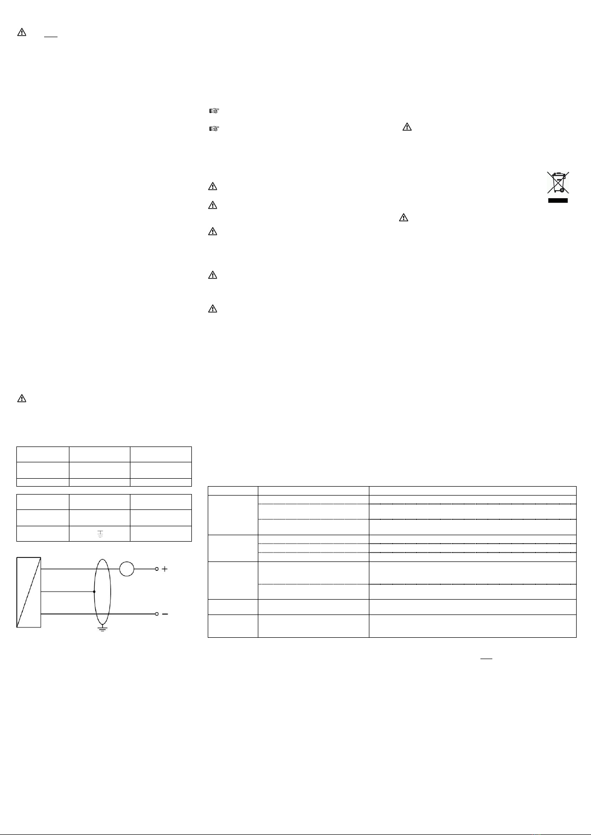
Wiring diagram:
!For devices with cable gland as well as cable socket,
you have to make sure that the external diameter of the
used cable is within the allowed clamping range.
Moreover you have to ensure that it lies in the cable
gland firmly and cleftlessly!
!For the installation of a device with cable outlet
following bending radiuses have to be complied with:
cable without ventilation tube:
static installation : 5-fold cable diameter
dynamic application: 10-fold cable diameter
cable with ventilation tube:
static installation : 10-fold cable diameter
dynamic application: 20-fold cable diameter
!Please note for devices with ISO 4400 plug and cable
socket, that the socket has to be mounted properly to
ensure the ingress protection mentioned in the data
sheet. Please check if the delivered seal is placed
between plug and cable socket. After connecting the
cable fasten the cable socket on the device by using the
screw.
!On devices with field housings, the terminal clamps are
situated under the metal cap. To install the device
electrically, the cap must be screwed off. Before the
cover is screwed on again, the O-ring and the sealing
surface on the housing have to be checked for
damages and if necessary to be changed! Afterwards
screw the metal cap on by hand and make sure that the
field housing is firmly locked again.
!Prevent the damage or removal of the PTFE filter which
is fixed over the end of the air tube on devices with
cable outlet and integrated air tube.
For the electrical connection a shielded and twisted
multicore cable has to be used.
Devices with TPE-cable
- Application in water with a temperature > 70°C
destroys the cable
Applications at media temperatures > 70°C have to be
clarified with BD|SENSORS in advance
5. Initial start-up
WARNING! Before start-up, the user has to check for
proper installation and for any visible defects.
WARNING! The device can be started and operated by
authorized personnel only, who have read and under-
stood the operating manual!
WARNING! The device has to be used within the
technical specifications, only (compare the data in the
data sheet)!
6. Placing out of service
WARNING! When dismantling the device, it must
always be done in the depressurized and currentless
condition! Check also if the medium has to be drained
off before dismantling!
WARNING! Depending on the medium, it may cause
danger for the user. Comply therefore with adequate
precautions for purification.
7. Maintenance
In principle, this device is maintenance-free. If desired, the
housing of the device can be cleaned when switched of
using a damp cloth and non-aggressive cleaning solutions.
With certain media, however, the diaphragm may be polluted
or coated with deposit. It is recommended to define corre-
sponding service intervals for control. After placing the
device out of service correctly, the diaphragm can usually be
cleaned carefully with a non-aggressive cleaning solution
and a soft brush or sponge. If the diaphragm is calcified, it is
recommended to send the device to BD SENSORS for
decalcification. Please read therefore the chapter “Repair”
below.
!An incorrect cleaning can cause irreparable damages
on diaphragm. Never use spiky objects or pressured air
for cleaning the diaphragm.
8. Error handling
9. Service / Repair
9.1 Recalibration
During the life-time of a transmitter, the value of offset and
span may shift. As a consequence, a deviating signal value
in reference to the nominal pressure range starting point or
end point may be transmitted. If one of these two phenom-
ena occurs after prolonged use, a recalibration is recom-
mended to ensure furthermore high accuracy.
9.2 Return
Before every return of your device, whether for recalibration,
decalcification, modifications or repair, it has to be cleaned
carefully and packed shatter-proofed. You have to enclose a
notice of return with detailed defect description when
sending the device. If your device came in contact with
harmful substances, a declaration of decontamination is
additionally required. Appropriate forms can be downloaded
from our homepage www.bdsensors.com. Should you
dispatch a device without a declaration of decontamination
and if there are any doubts in our service department
regarding the used medium, repair will not be started until an
acceptable declaration is sent.
If the device came in contact with hazardous
substances, certain precautions have to be
complied with for purification!
10. Disposal
The device must be disposed according to the
European Directives 2002/96/EG and
2003/108/EG (on waste electrical and electronic
equipment) Waste of electrical and electronic
equipment may not be disposed by domestic
refuse!
WARNING! Depending on the measuring medium,
deposit on the device may cause danger for the user
and the environment. Comply with adequate precau-
tions for purification and dispose of it properly.
11. Warranty conditions
The warranty conditions are subject to the legal warranty
period of 24 months from the date of delivery. In case of
improper use, modifications of or damages to the device, we
do not accept warranty claims. Damaged diaphragms will
also not be accepted. Furthermore, defects due to normal
wear are not subject to warranty services.
12. Declaration of conformity / CE
The delivered device fulfils all legal requirements.
The applied directives, harmonised standards and docu-
ments are listed in the EC declaration of conformity, which is
available online at: http://www.bdsensors.com.
Additionally, the operational safety is confirmed by the CE
sign on the manufacturing label.
Electrical connection
ISO 4400
Cable colours
(DIN 47100)
Supply +
Supply −1
2 white
brown
Ground
yellow/black
yellow/black
supply +
supply –
VS
A
p
I
Malfunction Possible cause Error detection / corrective
no output
signal
wrong connected inspect the connection
line break inspect all line connections necessary to supply the device (including
the connector plugs)
defective amperemeter (signal input)
inspect the amperemeter (fine-wire fuse) or the analogue input of the
PLC
analogue
output signal
too low
load resistance too high verify the value of the load resistance
supply voltage too low verify the output voltage of the power supply
defective energy supply inspect the power supply and the applied supply voltage at the device
small shift of
output signal
diaphragm is highly contaminated careful cleaning with non-aggressive cleaning solution and a soft
brush or sponge; incorrect cleaning can cause irreparable damages
on diaphragm or seals
diaphragm is calcified or coated with
deposit
if possible, it is recommended to send the device to BD SENSORS for
decalcification or cleaning
large shift of
output signal
diaphragm is damaged (caused by
overpressure or manually)
check the diaphragm; if it is damaged, please send the device to
BD SENSORS for repair
wrong or no
output signal manually, thermical or chemically
damaged cable
check the cable; a possible consequence of a damaged cable is pitting
corrosion on the stainless steel housing; if you determine this please
return the device to BD SENSORS for repair
If you detect an error, please try to eliminate it by using this table or send the device to our service address for repair.
!Improper action and opening can damage the device. Therefore repairs on the device may only be executed by the manufac-
turer!
This manual suits for next models
3
Other BD Sensors Accessories manuals


