BDR Thermea Group 28220 User manual
Installatiehandleiding - Installation manual - Manuel d’installation
Installationsanleitung - Manual de instalación
Manuale d’installazione - Instalação manual
nl en fr de es it pt
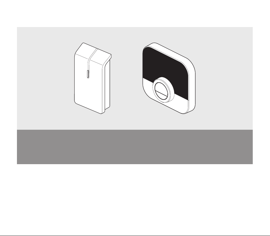
Wireless thermostat
• Lees en bewaar deze handleiding
• Read and keep this manual
• Lire et conserver ce manuel
• Bitte diese Anleitung lesen und aufbewahren
• Leia e guarde este manual
• Leggi e conserva questo manuale
• Lea y mantenga esta manual
7668357 - v.09 - 150620202
AD-2000027-03
E
DC
B
A
S1
F
G H
I
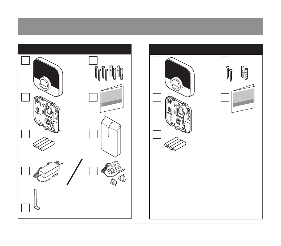
Inhoud doos - Set contents - Composition du kit - Set Inhalt
Contenido - Contenuto del kit - Conteúdos
AD-2000026-03
S2
E
DC
B
A
37668357 - v.09 - 15062020
AD-2000028-01
1
AD-2000029-02
≥ 50 cm
2

7668357 - v.09 - 150620204
AD-2000032-01
5
AD-2000033-02
6
AD-2000030-01
F
3
AD-2000031-01
4

57668357 - v.09 - 15062020
AD-2000047-02
I
7
AD-2000048-02
8
AD-2000034-02
F
G
1
2
F
H
1
2
9
7668357 - v.09 - 150620206
AD-2000035-01
EA
12
AD-2000036-01
13
AD-2000038-01
H
11
AD-2000037-02
10
77668357 - v.09 - 15062020
AD-2000039-02
1 2
14
AD-2000040-02
ø 6 mm
B
B
C
15
AD-2000041-01
16

7668357 - v.09 - 150620208
AD-2000044-01
19
AD-2000045-01
20
AD-2000042-02
ø 6 mm
B
B
17
AD-2000043-01
18
97668357 - v.09 - 15062020
AD-2000049-01
21
AD-2000050-01
22

7668357 - v.09 - 1506202010
nl - Informatie
1. Onderdelen:
A Thermostaat
B Schroeven en pluggen 6 mm x 30 mm
C Achterplaat
D Documentatie
E Batterijen
F Gateway
G Stroomadapter
H Stroomadapter
I Externe antenne
2. Stappen:
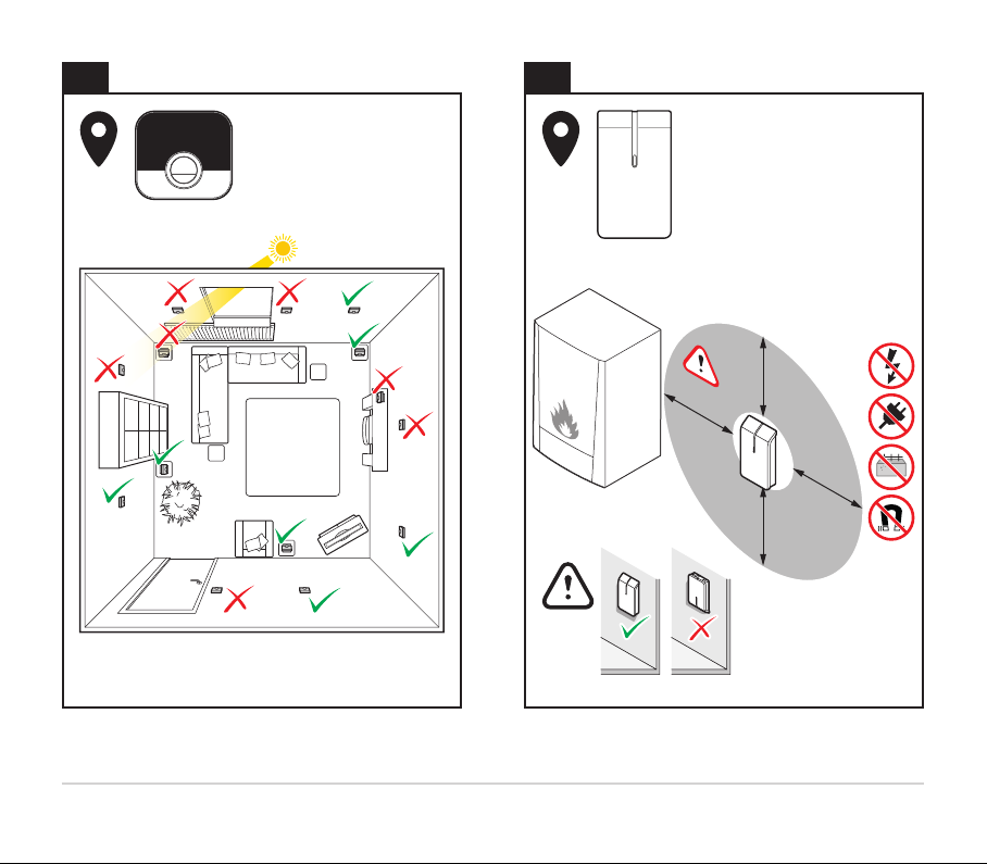
1. Kies de juiste locatie voor de thermostaat.
• Een locatie is geschikt als deze zich niet bevindt in de buurt van een warmtebron (bijv.
open haard, radiator, direct zonlicht, licht of kaarsen) of luchtstromen.
2. Kies de juiste locatie voor de gateway:
• De gateway is minstens 50 cm verwijderd van het klimaatapparaat.
• De gateway hangt niet op een locatie waar het klimaatapparaat zich tussen de gateway en
de thermostaat bevindt.
• De gateway is minstens 100 cm verwijderd van andere apparaten met een sterke
elektromagnetische straling, zoals een wasmachine, een droger of een luidspreker.
• Bevestig de gateway niet op een metalen oppervlak.
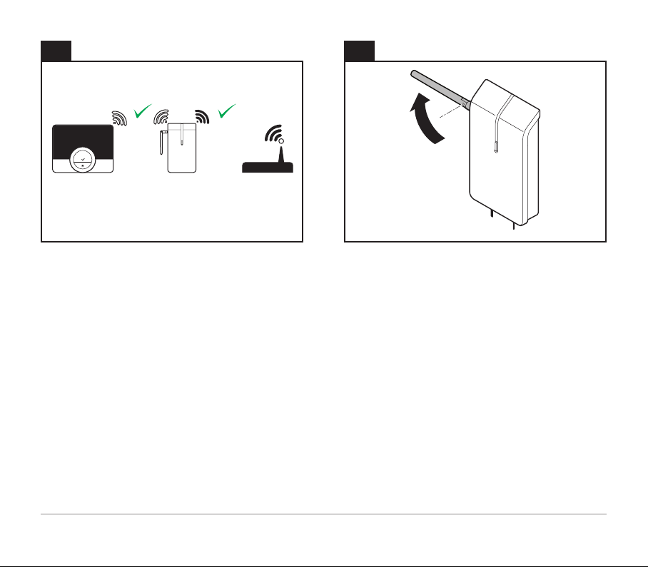
3. Verwijder de schroef uit de gateway.
4. Verwijder de kap van de gateway.
5. Verwijder de trekontlastingsklemmen.
6. Koppel het klimaatapparaat los van de stroomvoorziening.
7. Sluit de externe antenne aan.
8. Draai de antenne naar beneden in een verticale stand.
9. Sluit de vereiste draden aan:
9.1. Sluit de stroomadapter aan (onderdeel G of H).

117668357 - v.09 - 15062020
9.2. Sluit het klimaatapparaat aan op de gateway (onderdeel F):
Kabelvereisten
Maximale lengte 20 m 80 m 120 m
Dwarsdoorsnede 0,8 mm21,0 mm21,5 mm2
10. Sluit het klimaatapparaat aan op de stroomvoorziening.
11. Sluit de stroomadapter aan (onderdeel H).
12. Plaats de batterijen (onderdeel E).
13. Haal de thermostaat uit de stand-bymodus.
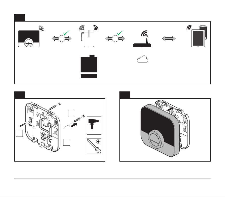
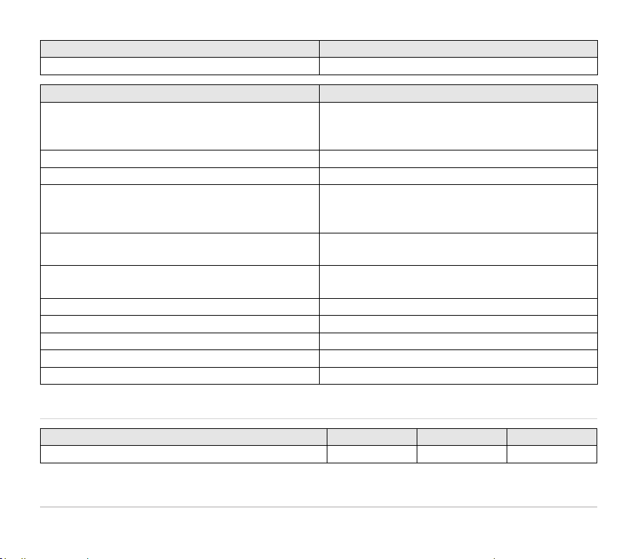
14. Stel de RF- en wifiverbinding in:
14.1. Stel de RF-communicatie tussen de gateway en de thermostaat in.
14.2. Stel de wificommunicatie tussen de gateway en de wifirouter in.
15. Plaats en bevestig de achterplaat (onderdeel C).
15.1. Bepaal de positie van de achterplaat (onderdeel C).
15.2. Boor de twee aangegeven gaten.
15.3. Plaats de pluggen (onderdeel B).
15.4. Zet hem vast met de schroeven (onderdeel B).
16. Bevestig de thermostaat op de achterplaat.
17.
17.1. Bepaal de positie van de gateway.
17.2. Boor de twee aangegeven gaten.
17.3. Plaats de pluggen (onderdeel B).
17.4. Zet hem vast met de schroeven (onderdeel B).
18. Bevestig de trekontlastingsklemmen.
19. Bevestig de kap.
20. Zet hem vast met de schroef.
21. Test de RF- en wifiverbinding.
22. Draai de antenne in een horizontale stand als de wifiverbinding niet goed is.

7668357 - v.09 - 1506202012
3. Beoogd gebruik
• De gateway is bedoeld als communicatie-interface tussen een klimaatapparaat (bijv. ketel of
warmtepomp) en de thermostaat.
• De gateway 14 ondersteunt de communicatieprotocollen OpenTherm, Aan/uit of RUB.
• De gateway 18 ondersteunt de communicatieprotocollen OpenTherm, Aan/uit, RUB of BSB.
4. Installatie
De installatie van de gateway moet worden uitgevoerd door een gekwalificeerd persoon.
Inbedrijfstelling
De inbedrijfstelling van de gateway vereist geen speciale procedure. Raadpleeg indien nodig de
gebruikershandleiding van de thermostaat voor meer informatie.
5. Referentiedocumenten
Op de gateway zit een label met de betekenis van de led-aanduidingen. De gateway maakt
deel uit van uw klimaatsysteem. Raadpleeg voor meer informatie de productinformatie van de
thermostaat of het klimaatapparaat.
6. Reiniging
De gateway en de thermostaat kunnen gereinigd worden met een licht bevochtigde doek. Gebruik
geen agressieve of schurende middelen.
7. Probleemoplossing
Bij een probleem met uw thermostaat, gateway en/of klimaatinstallatie raadpleegt u de betreffende
gebruikershandleiding. Als het probleem aanhoudt, neemt u contact op met uw installateur of
dealer.
8. Demontage
Open of demonteer de gateway nooit. Neem contact op met uw installateur of dealer als er zich
een probleem voordoet.
Verwijdering

137668357 - v.09 - 15062020
De gateways zijn een gangbaar elektronisch laagspanningsapparaat. Voer de gateway af op een
milieuvriendelijke manier en in overeenstemming met de lokale regelgeving.
9. Technische specificaties
Afmetingen Gateway Thermostaat
Breedte x hoogte x diepte (max. afmetingen) 83 x 145 x 28 mm 121 x 93 x 28 mm
117 x 107 x 28 mm
Voeding Gateway Thermostaat
Spanning 5 V 4 x AAA-batterijen
1,5 V
Maximaal opgenomen vermogen 4 W 0,25 mW
Max. uitgezonden RF-vermogen Gateway Thermostaat
WIFI 2,4 GHz +20 dBm -
868 MHz (RAMSES) +14 dBm +14 dBm
Elektrische aansluiting Gateway Thermostaat
Maximale kabellengte 50 m -
Maximale kabelweerstand 2 x 5 Ω -
Omgevingscondities Gateway en thermostaat
Opslagtemperatuur -25 °C tot +70 °C
Relatieve luchtvochtigheid 5% tot 95%, condensatie niet toegestaan
Bedrijfsomstandigheden van 0 °C tot 60 °C

7668357 - v.09 - 1506202014
Isolatie Gateway en thermostaat
IP-klasse IP21
Voldoet aan de normen Gateway en thermostat
NEN-EN-IEC 60335-1 2012
NEN-EN-IEC 60335-1 2012/C11 2014
NEN-EN-IEC 60335-1 2012/A11 2014
Huishoudelijke en soortgelijke elektrische
toestellen
2014/30/EU Laagspanningsrichtlijn (LVD)
2014/53/EU Richtlijn voor radio-apparatuur (RED)
2015/863/EU RoHS3 Richtlijn betreffende beperking van het gebruik
van bepaalde gevaarlijke stoffen in elektrische
en elektronische apparatuur (RoHS3)
2012/19/EU Richtlijn betreffende afgedankte elektrische en
elektronische apparatuur (AEEA)
1907/06/EG Verordening inzake de registratie en
beoordeling van en de autorisatie en
beperkingen ten aanzien van chemische stoffen
(REACH)
EN 55022-2011 Uitrusting voor informatietechnologie
EN 55024-2010 Immuniteit
EN 60068-2-6 Trillingstest

157668357 - v.09 - 15062020
Voldoet aan de normen Gateway en thermostat
EN 60068-2-27 Schoktest
OpenTherm V3.1
10. ErP Fiche-informatie
Gateway en thermostaat Thermostaat (1) Thermostaat (2) Thermostaat (3)
Klasse V VI IV
Bijdrage aan energie-efficiëntie voor
ruimteverwarming
3% 4% 2%
(1) Bij modulerende ketel.
(2) Bij modulerende ketel met
buitentemperatuursensor.
(3) Bij aan/uit-ketel.
Zie de achterzijde voor contactgegevens.
11. EG Conformiteitsverklaring
Het toestel is conform het in de EG conformiteitsverklaring beschreven standaardtype. Het is
vervaardigd en in bedrijf genomen overeenkomstig de Europese richtlijnen.
De originele conformiteitsverklaring is bij de fabrikant op te vragen.
https://declaration-of-conformity.bdrthermeagroup.com

7668357 - v.09 - 1506202016
en - Information
1. Parts:
A Thermostat
B Screws and plugs
C Back plate
D Documentation
E Batteries
F Gateway
G Power adapter
H Power adapter
I External antenna
2. Steps:
1. Choose the right location for the thermostat.
• A place is suitable if it is away from heat sources (fireplace, radiator, direct sunlight, light,
candles, etc.) and away from draughts.
2. Choose the right location for the gateway:
• The gateway is at least 50 cm from the climate appliance.
• The gateway is not at a place where the climate appliance is between the gateway and the
thermostat.
• The gateway is at least 100 cm from any other device with a strong electromagnetic
radiation, like washing machine, dryer or hi-fi speaker.
• You do not mount the gateway on a metal surface.
3. Remove the screw from the gateway.
4. Remove the cover from the gateway.
5. Remove the cable strain relief clamps.
6. Disconnect the climate appliance from the power supply.
7. Connect the external antenna.
8. Turn the antenna down to a vertical position.
9. Connect the necessary wires:
9.1. Connect the power adapter (part G or H).

177668357 - v.09 - 15062020
9.2. Connect the climate appliance to the gateway (part F):
Cable requirements
Maximum length 20 m 80 m 120 m
Cross-sectional area 0.8 mm21.0 mm21.5 mm2
10. Connect the climate appliance to the power supply.
11. Connect the power adapter (part H).
12. Insert the batteries (part E).
13. Awaken the thermostat.
14. Setup the RF and wi-fi connection:
14.1. Setup the RF communication between the gateway and the thermostat.
14.2. Setup the wi-fi communication between the gateway and the wi-fi router.
15. Position and mount the back plate (part C).
15.1. Determine the position of the back plate (part C).
15.2. Drill the 2 marked holes.
15.3. Fit the plugs (part B).
15.4. Secure with screws (part B).
16. Mount the thermostat on the back plate.
17.
17.1. Determine the position of the gateway.
17.2. Drill the 2 marked holes.
17.3. Fit the plugs (part B).
17.4. Secure with screws (part B).
18. Mount the cable strain relief clamps.
19. Mount the cover.
20. Secure with screw.
21. Test the RF and wi-fi connections.
22. If the wi-fi connection should not be sufficient, turn the antenna to a horizontal position.
3. Intended use
• The gateway is designed to operate as a communication interface between a climate appliance

7668357 - v.09 - 1506202018
(e.g. boiler, heat pump, etc) and the thermostat.
• The gateway 14 supports the communication protocols OpenTherm, On/Off or RUB.
• The gateway 18 supports the communication protocols OpenTherm, On/Off, RUB or BSB.
4. Installation
The installation of the gateway must be performed by a qualified person.
5. Commissioning
No special procedure is required for the commissioning of the gateway.
Consult the user manual of the thermostat for more information if required.
6. Reference documentation
On the gateway you will find a label that explains the meaning of the LED indications. The gateway
will be a part of your climate system. Consult the product information of the thermostat or climate
appliance for more information.
7. Cleaning
The gateway and thermostat can be cleaned with a light moist cloth. Do not use any aggressive or
abrasive agents.
8. Trouble shooting
In case of any problems with your thermostat, gateway and/or climate installation, please consult
the different user manuals. Consult your installer or sales outlet for unsolved issues.
9. Dismantling
Never open or dismantle the gateway. Consult your installer or sales outlet in case of any
problems.

197668357 - v.09 - 15062020
10. Disposal
The gateways are a regular low voltage electronic device. Dispose the gateway in an
environmentally friendly way, in accordance with local regulations.
11. Technical specifications
Dimensions Gateway Thermostat
Width x height x depth (max. dimensions) 83 x 145 x 28 mm 121 x 93 x 28 mm
117 x 107 x 28 mm
Max. transmitted RF power Gateway Thermostat
WIFI 2.4GHz +20 dBm -
868MHz (RAMSES) +14 dBm +14 dBm
Power supply Gateway Thermostat
Voltage 5V 4 x AAA Batteries 1.5V
Maximum power consumption 4 W 0.25 mW
Electrical connection Gateway Thermostat
Maximum cable length 50 m -
Maximum cable resistance 2 x 5 Ω -
Ambient conditions Gateway and Thermostat
Storage temperature from -25°C to +70°C
Relative humidity from 5% to 95%, condensation is not allowed
Operating conditions from 0°C to 60°C
7668357 - v.09 - 1506202020
Insulation Gateway and Thermostat
IP-classification IP21
Compliant with standards Gateway and Thermostat
NEN-EN-IEC 60335-1 2012
NEN-EN-IEC 60335-1 2012/C11 2014
NEN-EN-IEC 60335-1 2012/A11 2014
Household and similar electrical appliances
2014/30/EC Low Voltage Directive (LVD)
2014/53/EU Radio Equipment Directive (RED)
2015/863/EU RoHS3 Restriction of the use of certain Hazardous
Substances in electrical and electronic
equipment (RoHS3)
2012/19/EU Waste Electrical & Electronic Equipment
(WEEE)
1907/06/EC Registration, Evaluation, Authorisation and
Restriction of Chemicals (REACH)
EN 55022-2011 Information technology Equipment
EN 55024-2010 Immunity
EN 60068-2-6 Vibration test
EN 60068-2-27 Shock test
OpenTherm V3.1
12. ErP Fiche information
Gateway + Thermostat Thermostat (1) Thermostat (2) Thermostat (3)
Class V VI IV
Table of contents


