Document No. 129-129
Installation Instructions
Rev. 3, August, 2000
Information in this publication is based on current specifications. The company reserves the right to make changes in specifications and
models as design improvements are introduced. © 2000 Siemens Building Technologies, Inc.
Siemens Building Technologies, Inc.
Landis & Staefa Division
1000 Deerfield Parkway
Buffalo Grove, IL 60089-4513
U.S.A.
Your feedback is important to us. If you have
comments about this document, please send
them to technical.editor@sbt.siemens.com
Document No. 129-129
Printed in the U.S.A.
Page 3 of 3
Installation, Continued
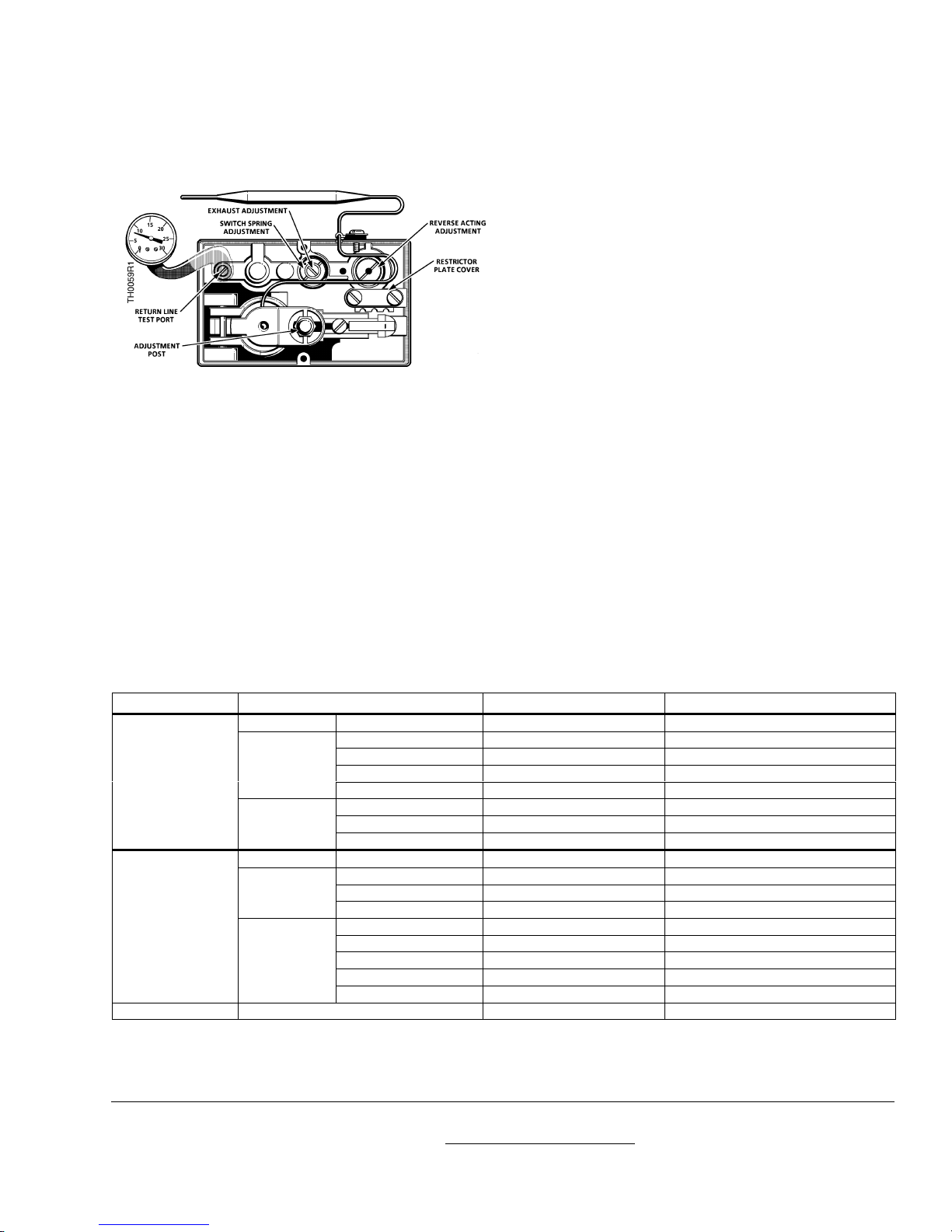
Figure 5. Heating/Cooling Changeover.
4. Rotate adjustment post to give an output within
1/2 psi (3.4 kPa) of calibration pressure.
5. Adjust PRV for 18 psi (124 kPa) air supply;
observe the control pressure. If not within
1/2 psi (3.4 kPa) of calibration pressure, adjust
the reverse acting adjustment until it is. Apply
ambroid to the screw setting.
6. Remove test port gauge; close bleed screw.
7. Replace cover and knob.
8. Lock knob in place with pointer at bulb
temperature.
9. Set knob at desired temperature setting.
Heat–cool thermostat changeover
See
Table 1
for air pressure and changeover
pressure.
The changeover is a factory adjustment; it is sealed
with ambroid and does not require field adjustment.
If, for some reason, this adjustment is disturbed, re-
adjust as follows (See
Figure 5
):
1. Supply the thermostat with an air supply
pressure equal to the appropriate changeover
pressure (
Table 1
).
2. With the exhaust adjustment (center screw)
backed out several turns, turn the switch spring
adjustment (outer screw) down snug, and then
back off until air can be heard bleeding out.
3. Turn the exhaust adjustment down snug and
back off approximately 1/8 turn.
4. Seal both screws with ambroid to prevent
further movement.
The installation is now complete.
Reference
Technical Instructions
TH 188-2
155-064P25
Table 2. Troubleshooting.
Complaint Check Possible Cause Corrective Action
Supply Air No Air As Required
Calibration Out of calibration Recalibrate
Restrictor Clogged or dirty Clean or replace
Sensing element Loss of charge Replace sensing element
*Heating
25 psi
(172 kPa) Direct acting stage Internal binding or leaking Replace thermostat
Calibration Out of calibration Recalibrate
Throttling pin Dirt built up around pin Clean or replace nozzle assembly
Return line
pressure
0 psi
(0 kPa) *Cooling
18 psi
(124 kPa) Reverse acting stage Internal binding or leaking Replace thermostat
Supply Air Pressure Too High As Required
Calibration Out of calibration Recalibrate
Throttling Pin Dirt built up around pin Clean or replace nozzle assembly
*Heating
25 psi
(172 kPa) Direct acting stage Internal binding Replace thermostat
Calibration Out of calibration Recalibrate
Restrictor Clogged or dirty Clean or replace
Sensing element Loss of charge Replace sensing element
Reverse acting stage Improperly adjusted Re-adjust
Return line
pressure
18 psi
(124 kPa) or
greater *Cooling
18 psi
(124 kPa) Reverse acting stage Internal leaks or binding Replace thermostat
Excessive cycling Lever assembly Sticking or binding of levers As required
* See
Table 1
for Honeywell and Johnson Controls pressures.