BE SP-500TD User manual

User Manual
SUBMERSIBLE
PUMP
610.536

2
TABLE OF CONTENTS
Introduction
3 Using the Operators Manual
Product Identification
4 Pressure Washer
Components
5 Components Diagram
Product Information
6 Product Information
Operating Instructions
7 Pre-operation Instructions
8 Operating Instructions
Technical Information
10 Product specications
Troubleshooting
11 How to Start your Pressure Washer

3
Using the Operator’s manual
The operating manual is an important part of your Submersible Pump. It
should be read thoroughly before initial use, and referred to often to make
sure adequate safety and service concerns are being addressed.
Reading the owner’s manual thoroughly will help avoid any personal injury or
damage to your pump. The information in this manual will oer you the most
eective tools for cleaning as well as the safest. By knowing how best to
operate this machine you will be better positioned to show others who may
also operate the unit.
This manual contains information for the complete range of BE submersible
pumps. It is placed in order starting from the safety requirements to the
operating functions of your pump. You can refer back to the manual at any
time to help troubleshoot any specic operating functions, so store it with the
machine at all times.
Attention: Read through the complete
manual prior to the initial use of your
Submersible Pump
GROUNDING
The grounding conductor of the power cord and switch are terminated
in listed double crimpled closed loop connectors that are secured to the
motor enclosure by a screw that engages at least two threads into metal
and star washer or lockwasher. Connectors are secured using crimping
tool recommended by the manufacturer.
INTRODUCTION

4
INTRODUCTION
Congratulations on your purchase of a BE Power Equipment water
pump. You can be confident that this machine is constructed and tested
with optimum performance and quality in mind.
Reading this manual will help get you the best results for set-up,
operation, maintenance and avoid personal injury or damage to your
machine. By knowing how best to operate this machine, you will be
better positioned to show others who may also operate the unit.
All the information in this manual is based on the latest product
information available at the time of printing. BE Power Equipment
reserves the right to make changes at any time without notice or
incurring any obligation.
Owner/Operator Responsibility
The owner/operator must have a thorough understanding of the
operation, maintenance and dangers associated with using this machine.
It must be understood that it is ultimately up to the owner/operator to
safely use this machine as outlined in this manual.
This manual is considered a part of the machine and needs to be kept
in a safe location. If the machine is resold or given to someone else, this
manual needs to be included.
Product Registration
Please register your product online to get the maximum benefit
from your warranty. Use the QR code below or register online at:
bepowerequipment.com/product-registration
It is recommended that you record the product identification numbers
in this manual. These numbers are important to have on hand if you
need to contact technical support (1-866-850-6662). The model and
serial number can be found on the box and on decal on the machine.
PRODUCT IDENTIFICATION
Model Number:
Serial Number:
Date of Purchase:
Dealer Name:

5
COMPONENTS
C8
9
B
1
2
3
4
56
7
1¼”
32mm
1”
25mm
½”
13mm
5
/8”
15mm
¾”
19mm
D E

6
1. Information Concerning the Operating Instructions
Please read these operating instructions carefully. Follow the information
given. Use the operating instructions to get acquainted with the proper
use of your submersible pump.
**For safety reasons, people who are not familiar with these
operating instructions should not use this Submersible Pump.
Following the operating instructions supplied by the manufacturer is
a prerequisite for the proper use of the pump.
2. Application Range and Liquids to be Pumped
Submersible pumps have been designed for private use around your
house and garden. Submersible pumps are predominantly used for
drainage after ooding, transferring liquids, draining containers, taking
water from wells and shafts, draining boats and yachts as well as water
aeration and circulation for limited period of time.
Only clean or slightly contaminated water can be handled by these pumps.
The max particle size allowable is 0.08”, 2mm, except the Trash Pump
Model # ST-900SD which allows .25” or 6.35mm. Soapy water can also
pass through the pumps without issue. These pumps are not designed
for continuous operation (e.g. continuous circulating operation). If used
for these applications, additional wear and tear will result.
WARNING
Corrosive, easily combustible, or explosive substances
(e.g. gasoline, petroleum, nitro thinner), fats, oils, salt and waste
water of toilets and urinals must not be pumped.
The temperature of the liquids handled must not exceed 35ºC.
PRODUCT INFORMATION

7
PRE-OPERATING INSTRUCTIONS
4. Measures Before Operation
4.1 Hose Connection
Screw the supplied ttings onto the pump, as described in illustration C.
The universal tting (7) allows connection of 1¼”(32mm), 1”(25mm),
3/4”(19mm) as well as of 1/3”(13mm) hoses, according to your individual
requirements, 5/4”(32mm) hoses are connected to the pump via the step
nipples of universal tting, 3/4”(19mm ) and 1/2” (13mm) hoses with
Hose connection system parts (illustration D). It is recommended
to x 1¼”(32mm) and 1” (25mm) hoses additional with a hose clamp.
Components of the universal tting which you don’t require (when
connecting 1¼” (32mm) hoses are detached with a knife from the
universal tting, illustration E.)
Best results in delivery capacity are achieved when using 5/4”(32mm)
hoses.
4.2 Float Switch Adjustment
The oat switch (5) automatically switches on the pump at a water height
of approx. 21”(53cm) and automatically switches o at a water height of
approx 2”(5cm) by xing the oat switch cable to the oat switch lock (3).
The cut-in/cut-out height can be adjusted individually.
4.3 Location and Transport
• Please ensure that the pump is placed in a stable position, especially for
automatic operation.
• In the event of automatic operation, ensure that the oat switch is able to
to move freely.
• Take care that the pump is located in a way ensuring that the inlet
openings at the suctions base are obstructed neither completely nor
partly. Therefore, it is advisable to place the pump for example on a brick.
• Don’t use power cable or oat switch for carrying or hanging up the
pump. When submerging the pump in wells or shafts, please use a rope
fastened to the carrying handle (2).
3. Functional Parts (Illustrations B & C on page 5)
1. Power Cable
2. Carrying Handle
3. Float Switch Lock
4. Vent Valve
5. Float Switch
6. Suction Base
7. Universal Fitting
8. Phillips Recessed Head Screws
9. Turbine

8
5. Operation
5.1 Automatic Operation
After having connected the power cable, the pump is automatically
switched on at a denite water height (cut-in height) and switches
o as soon as the water level drops down to a denite water height
(cut-out height).
5.2 Manual Operation
In case of manual operation, the Submersible Pump starts when the
power cable has been connected and the oat switch has been lifted.
6. Safety Tips before Operation
• For safety reasons, the Submersible Pump should always be operated
via a circuit breaker safety switch (FI switch) with rated fault current
of <30mA.
• Always check the pump (above all power cable and plug) before
each operation. A damaged pump must not be used. It is absolutely
necessary to have the pump inspected by a service center.
• Ensure that the electrical connections are made within a dry area,
protected from ooding.
• Protect plug and power cable (1) from heat, oil and sharp edges.
• Check line voltage. Data indicated on the type plate must match
technical data of the main supply.
• Children are not allowed to operate the pump. Ensure that they are kept
away from the work area.
• Before use, clear the outlet rst.
Observe the minimum water level (see point 9,“Technical Data”).
Observe max. delivery height (see point 9,“Technical Data”).
Have a professional electrician or your service center replace the
damaged cable. Please use a protective switch (drain current is no
more than 30mA).
PRE-OPERATING INSTRUCTIONS
WARNING
Always unplug the pump before performing maintenance.
Repairs on electrical parts should only be done at a Service Center.

9
OPERATING INSTRUCTIONS
7. Operating Tips
• Dry-running operation causes increased wear and should be avoided at
all costs. This means that the unit must be switched o if water ceases
to ow at any point.
• The pump is automatically switched o upon overheating by the built-in
thermal motor protector. After having cooled down, the motor
automatically switches on again. For more information, see Trouble
Shooting Guide, point 10.
• When unplugging the unit, pull from the shell, not the cord.
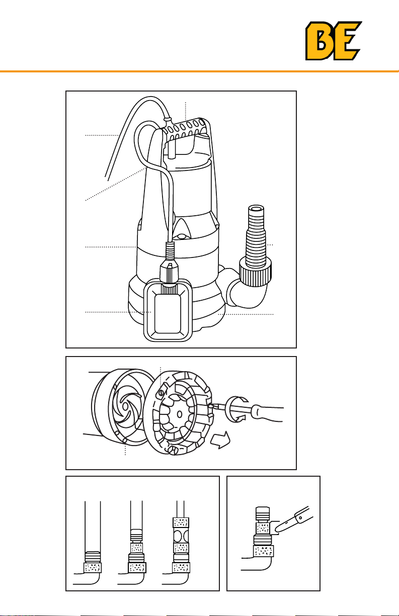
• The power cable (1) must not be used for mounting or relocating the
pump for submerging or lifting/securing the pump. Fix a rope to the
carrying handle (2).
• After pumping chlorinated swimming pool water or other liquids that can
leave residue, the pump should be rinsed with clear water.
• Sand and other abrasive material in the liquid cause increased wear,
reducing the output of the pump over time.
• Avoid running of the pump for more than 10 mins against closed
delivery side of the pump.
• The Submersible Pumps drains up to a residual water height
of approx. 0.2”(5mm). This at suction height is only reached during
manual operation (see point 5,“Operation”), but not during automatic
operation.
• The Submersible Pump is equipped with an automatic deaerating
device whose function is to remove probable air pockets in the pump.
If the water level drops below the vent valve (4), some water ows
penetrates outside through the vent valve. This is not a defect of your
pump, but rather serves to deaerate the pump.
• In the event of manual operation, the pump has sucked o completely
and water ows again after the pump operation, the pump isn’t deaer-
ated automatically. Then, the pump has to be switched o for a short
time and then switched on again.
8. Maintenance, Care and Storage.
Submersible pumps are virtually maintenance free. That being said, it is
important to ensure that they are not used for anything other than their
intended application. Misuse can permanently damage the pump.
In case of contamination inside the pump, the suction base (6) can be
taken o by unscrewing the 3 Phillips recessed head screws (8).
This the turbine space can be cleaned. For safety reasons, a damaged
turbine (9) can only be exchanged by the Service Center.
To protect the pump from frost damage, store the pump in a dry place.

10
9. Technical Data
SP-500TD SP-550SD SP-600BD SP-650BD SP-750TD SP-900SD ST-900SD
Max. Delivery Capacity 1580 GPH
5980 l/h
2905 GPH
11,000 l/h
3036 GPH
11,500 l/h
3036 GPH
11,500 l/h
2905 GPH
10,996 l/h
4360GPH
16,500 l/h
4356GPH
16,490 l/h
Max. Delivery Height 28.5 ft
8.6m
28 ft
8.5m
24 ft
7.3m
24 ft
7.3m
27 ft
8.5m
31 ft
9.4m
34 ft
10.3m
Contaminated Water
with particle size of
max.
0.2 in
5mm
0.2 in
5mm
0.2 in
5mm
0.2 in
5mm
0.2 in
5mm
0.2 in
5mm
1.4 in
35mm
TECHNICAL DATA

11
10. Trouble-Shooting Guide
Problem Probable Cause Remedy
Pump is running
but doesn’t
transfer water.
Air cannot escape, since
pressure line is closed.
Open pressure line
(e.g. kinked pressure pipe.)
Air locks in the suction
base.
Wait for max 60 seconds
until the pump deaerates
automatically over the
vent valve. If necessary,
switch o and start it
again.
Turbine clogged Clean turbine (point 8).
When starting the pump,
water height falls below
the min. water level.
Submerge pump deeper
(see min. water level,
point 9.)
Pump doesn’t
start or suddenly
stops during
operation.
Thermal overload switch
has switched the pump
o due to overheating.
Disconnect plug and
clean turbine.
(point 8). Note that max
water temp is 35ºC.
No power
Check fuses and electrical
connections
Dirt particles (e.g. pebbles)
are jammed in the
suction base.
Disconnect plug and
clean suction base
(point 8).
Pump runs but
output suddenly
decreases.
Suction base is clogged. Disconnect plug and
clean suction base
(point 8).
Please note that any damage caused to the machine due to lack of
maintenance or improper use will not be covered under warranty.
TROUBLESHOOTING GUIDE

If you need assistance with the assembly or
operation of your Submersible Pump please call
1-866-850-6662

Si vous avez besoin d’assistance avec
l’assemblage ou l’opération de ce Pompe
Submersible, s’il vous plait appelez le
1-866-850-6662

11
10. Guide de dépannage
Problème Cause probable Solution
La pompe
fonctionne, mais
n’ore pas son plein
rendement
L’air ne peut s’échapper,
puisque la ligne de
pression est fermée
Ouvrir ou dégager la ligne
de pression (par exemple,
le tuyau de pression peut
être plié).
L’air se bloque dans le
socle d’aspiration.
Attendez maximum 60
secondes jusqu'à ce que
la pompe désaère
automa
tiquement dans la
soupape
de dégagement.
Si nécessaire, éteignez-la
et recommencez.
La turbine est obstruée. Nettoyer la turbine
(point 8).
Lors du démarrage de la
pompe, la hauteur de l’eau
descend en dessous du
niveau d’eau minimum.
Immergez la pompe plus
bas (voir niveau d’eau
minimum, point 9).
La pompe ne
démarre pas ou
s’arrête brusquement
pendant l’opération
L’Interrupteur thermique a
mis la pompe en arrêt dû à
une surchaue
Débranchez la prise et
nettoyer la turbine
(point 8). Respecter la
température maximale
de l’eau de 35oC.
Il n’y a pas de courant. Vérier les fusibles et les
connexions électriques
Des particules de saleté
(cailloux par exemple) sont
coincées dans la socle
d’aspiration
Débrancher la che et
nettoyer le socle
d’aspiration (point 8).
La pompe
fonctionne mais
le débit diminue
brusquement.
La pompe fonctionne
mais le débit diminue
brusquement.
Débrancher la che et
nettoyer le socle
d’aspiration (point 8).
Nous signalons expressément que, conformément à la responsabilité
du fabricant, nous ne sommes pas responsables des dommages causés
par le matériel, si cela est dû à une réparation incorrecte, à des pièces
échangées en n’utilisant pas nos pièces d’origine ou approuvées par
nous et si les réparations n’ont pas été eectuées par le Service
technique. La même chose s’applique aux pièces et accessoires
complémentaires.
GUIDE DE DÉPANNAGE

10
9. Informations techniques
INFORMATIONS TECHNIQUES
SP-500TD SP-550SD SP-600BD SP-650BD SP-750TD SP-900SD ST-900SD
Max. Capacité de
livraison
1580 GPH
5980 l/h
2905 GPH
11,000 l/h
3036 GPH
11,500 l/h
3036 GPH
11,500 l/h
2905 GPH
10,996 l/h
4360GPH
16,500 l/h
4356GPH
16,490 l/h
Max. Hauteur de
livraison
28.5 ft
8.6m
28 ft
8.5m
24 ft
7.3m
24 ft
7.3m
27 ft
8.5m
31 ft
9.4m
34 ft
10.3m
Eau contaminée avec
une taille de particule
de max.
0.2 in
5mm
0.2 in
5mm
0.2 in
5mm
0.2 in
5mm
0.2 in
5mm
0.2 in
5mm
1.4 in
35mm

9
7. Conseils d’utilisation
• La marche à sec provoque une usure accrue et doit être évitée.
Par conséquent, la pompe doit être immédiatement mise hors tension
lorsque l’eau ne s’écoule plus.
• La pompe s’arrête automatiquement en cas de surchaue grace à la
protection thermique intégré au moteur. Après avoir refroidi, le moteur
se remet automatiquement en marche. (consultez le guide de
dépannage, page 11)
• Pour débrancher, tirer sur la che, pas sur le câble d’alimentation.
• Le câble d’alimentation (1) ne doit pas être utilisé pour soulever ou sus-
pendre la pompe. Fixez plutôt une corde à la poignée de transport (2).
• Après avoir pompé l’eau chlorée de la piscine ou d’autres liquides lais-
sant des résidus, la pompe doit être rincée à l’eau claire.
• Le sable et autres matériaux abrasifs dans les liquides peuvent causer
une usure accrue et réduire la puissance des pompes.
• Évitez de faire fonctionner la pompe pendant plus de 10 minutes contre
une surface orant une résistance à l’évacuation des eaux.
• Les pompes submersibles aspirent l’eau jusqu’à une hauteur résiduelle
d’environ 5mm. Cette hauteur d’aspiration plane est atteinte seulement
en cas de fonctionnement manuel (voir le point 5,“Utilisation”), mais
pas en cas de fonctionnement automatique.
• La pompe submersible est équipée d’un dispositif automatique de
désaération dont la fonction est d’éliminer les bulles d’air probables
dans la pompe. Si le niveau d’eau descend en dessous de la soupape
d’aération (4), de l’eau pénètrent par l’extérieur à travers la soupape
d’aération. Ce n’est pas un défaut de la pompe, mais ça sert à la purger.
• Si, en cas de fonctionnement manuel, la pompe a aspiré l’eau complète-
ment et que cette dernière coule à nouveau après l’opération, la pompe
n’est pas désaérée automatiquement. La pompe doit alors être arrêtée
pendant un court moment, puis remise en marche.
8. Entretien et rangement
Les pompes submersibles sont pratiquement sans entretien.
AVERTISSEMENT
Toujours débrancher la pompe avant de procéder à l’entretien.
Les réparations sur les composantes électriques ne doivent être
effectuées qu’à un Centre de Service.
En cas de contamination à l’intérieur de la pompe, la base d’aspiration
(6) peut être retiré en dévissant les 3 vis cruciformes (8). Cet espace
de la turbine peut être nettoyé. Pour des raisons de sécurité une turbine
endommagée (9) ne peut être échangée que par le Centre de Service.
Pour protéger la pompe contre le gel, rangez la dans un endroit sec à
l’intérieur
UTILISATION ET ENTRETIEN

8
5. Utilisation
5.1 Fonctionnement automatique
Après avoir connecté le câble d’alimentation, la pompe est automatique-
ment activée à une hauteur d’eau déterminée et s’éteint dès que le niveau
d’eau descend jusqu’à une hauteur d’eau déterminée
5.2 Fonctionnement manuel
En cas de fonctionnement manuel, la pompe submersible se met en
marche lorsque le câble d’alimentation est branché et l’interrupteur à
otteur a été levée.
6. Conseils de sécurité avant utilisation
•Pour des raisons de sécurité, la pompe submersible doit toujours être branchée
dans un interrupteur de sécurité coupe-circuit (FI interrupteur) avec un
courant nominal par défaut de <30mA. • Toujours vérier la pompe
(surtout le câble d’alimentation et la che) avant
chaque opération. Une pompe endommagée ne doit pas être utilisée. Il
est absolument nécessaire de faire vérier l’appareil par un électricien.
• Veillez à ce que les connexions électriques soient réalisées dans un
endroit sec, à l’abri des inondations.
• Protégez la che et le câble d’alimentation (1) de la chaleur, de l’huile et
de tout objet tranchant.
• Vérier la tension de ligne. Les données indiquées sur la plaque
signalétique de l’appareil doivent correspondre aux données de
l’alimentation principale.
• Les enfants ne sont pas autorisés à faire fonctionner la pompe.
Gardez-les à l’écart de l’appareil branché.
• Avant toute utilisation, désactivez d’abord la prise de courant.
Observer le niveau d’eau minimum (voir point 9,“Caractéristiques
techniques”). Observez la hauteur de refoulement maximum (voir
point 9,“Caractéristiques techniques”). Demander à un électricien
professionnel ou à votre agent de remplacer tout câble endommagé.
S’il vous plaît utiliser un interrupteur de protection dont le courant ne
dépasse pas 30 mA.
Par conséquent, il est conseillé de placer la pompe, par exemple,
sur une brique
• Ne pas utiliser de câble d’alimentation ou l’interrupteur à otteur pour le
transport ou pour accrocher la pompe. Lors de l’immersion de la pompe
dans des puits, s’il vous plaît utiliser une corde qui est attachée à la
poignée de transport de la pompe (2).
MANUEL D’INSTRUCTION

7
3. Pièces fonctionnelles (Illustrations B & C page 4)
1. Câble d’alimentation
2. Poignée de transport
3. Cran de sécurité de l’interrupteur à otteur
4. Soupape d’aération
5. Interrupteur à otteur
6. Socle d’aspiration
7. Embout universel
8. Vis cruciformes
9. Turbine
4. Mesures à prendre avant l’utilisation
4.1 Raccordement du tuyau
Visser les raccords fournis sur la pompe, comme indiqué dans
l’illustration B. L’embout universel (7) permet la connexion des tuyaux
exibles de 32 mm (5/4“), 25 mm (1”), 19 mm (3/4 “) ainsi que celui
de 13mm (1/3“), en fonction de vos besoins individuels. Les tuyaux de
32mm (5/4”) sont raccordés à la pompe par les rainures de l’embout
universel. Les tuyaux de 19mm (3/4“) et de 13 mm (1/2” tuyaux) sont
installés grace à des pièces de raccordement ( voir illustration D). Il est
recommandé de xer les tuyaux de 32mm (5/4“) et de 25 mm (1”) avec
un collier de serrage.
Lors de la connexion du tuyau de 32mm (1/2“) , il faut couper avec un
couteau la partie exédente de l’embout universel.
Les meilleurs résultats dans la capacité d’exécution de la pompe sont
réalisés avec l’utilisation de tuyaux exibles de 32mm (5/4“).
4.2 Réglage de l’interrupteur à flotteur
Seule l’eau propre ou légèrement contaminée peut être manipulée par ces
pompes. La taille de particule maximale autorisée est de 0,08 “, 2 mm, à
l’exception du modèle de pompe à déchets # ST-900SD qui autorise 0,25”
ou 6,35 mm. L’eau savonneuse peut également traverser les pompes sans
problème. Ces pompes ne sont pas conçues pour un fonctionnement continu
(par exemple un fonctionnement à circulation continue). S’il est utilisé pour
ces applications, il en résultera une usure supplémentaire.
4.3 Positionnement et transport
• S’il vous plaît veillez à ce que la pompe soit placée dans une position
stable (surtout pour le fonctionnement automatique).
• En outre, veillez à ce que, en cas de fonctionnement automatique,
l’interrupteur à otteur puisse se déplacer librement.
• Veillez à ce que la pompe soit située de façon à garantir que l’ouverture
à la base d’aspiration ne soit obstruée ni totalement ni partiellement.
MODE D’EMPLOI AVANT UTILISATION

6
1. Renseignements concernant le mode d’emploi
S’il vous plaît lire attentivement ces instructions. Suivez les informations
fournies
. Utilisez le mode d’emploi an de vous familiariser avec l’utilisation
correcte de votre pompe submersible.
** Pour des raisons de sécurité, les personnes qui ne sont pas
familières avec ces instructions de fonctionnement ne devraient pas
utiliser cette pompe submersible.
Suivre les instructions d’utilisation fournies par le fabricant est une
condition préalable à la bonne utilisation et au bon fonctionnement
de la pompe
2. Domaines d’application et liquides pouvant être pompés
Les pompes submersibles ont été conçus pour un usage privé autour
de votre maison et de votre jardin. Les pompes submersibles sont
principalement utilisées, pour une période limitée, pour le drainage après
pliage, le transfert de liquides, le drainage des conteneurs, des bateaux
et des yachts, la prise d’eau dans les puits , ainsi que pour l’aération
et la circulation de l’eau.
Les pompes sont entièrement submersibles (étanches, scellées) et
peuvent être submergées jusqu’à une profondeur de:
Les liquides qui peuvent être traitées par la pompe submersible sont les
suivantes: l’eau propre ou légèrement usée (granulométrie max 5 mm ou
0,5 mm, à l’exception de ST-900SD qui est 1.4”, 35mm) et l’eau savon-
neuse. Les pompes ne sont pas conçus pour un fonctionnement continu
(par exemple, le fonctionnement continu de circulation), votre vie sera
raccourcie pompes en conséquence par une telle opération.
AVERTISSEMENT
Les substances corrosives, facilement inflammables ou explosives
(essence, le pétrole, diluant nitro), les graisses, les huiles, le sel
et les eaux usées des toilettes et des urinoirs ne doivent pas être
pompés. La température des liquides traités ne doit pas dépasser
35 ° C.
MODE D’EMPLOI AVANT UTILISATION

5
C8
9
B
1
2
3
4
56
7
1¼”
32mm
1”
25mm
½”
13mm
5
/8”
15mm
¾”
19mm
D E
DIAGRAMME
This manual suits for next models
6
Table of contents
Other BE Water Pump manuals
Popular Water Pump manuals by other brands

Sensidyne
Sensidyne Gilian 800i Quick start manual

Pfeiffer Vacuum
Pfeiffer Vacuum HiPace 800 operating instructions

BUSCH
BUSCH MINK MM 1104 CVM instruction manual

Graco
Graco ChemSafe 307 Instructions - parts

Trebor
Trebor MAXIM 50R-X12 Operation & maintenance manual

TTI
TTI DieselCaptain Operator's handbook

SAFEMATIC
SAFEMATIC 361034B Installation and Maintenance

GORMAN-RUPP PUMPS
GORMAN-RUPP PUMPS SFV4D Installation, operation and maintenance manual

XPOtool
XPOtool 15 l instruction manual

KNF
KNF N286.15 SP Original Operating and Installation Instructions

Ozito
Ozito PSDWK-1000 instruction manual

Edwards
Edwards nEXT200200 instruction manual