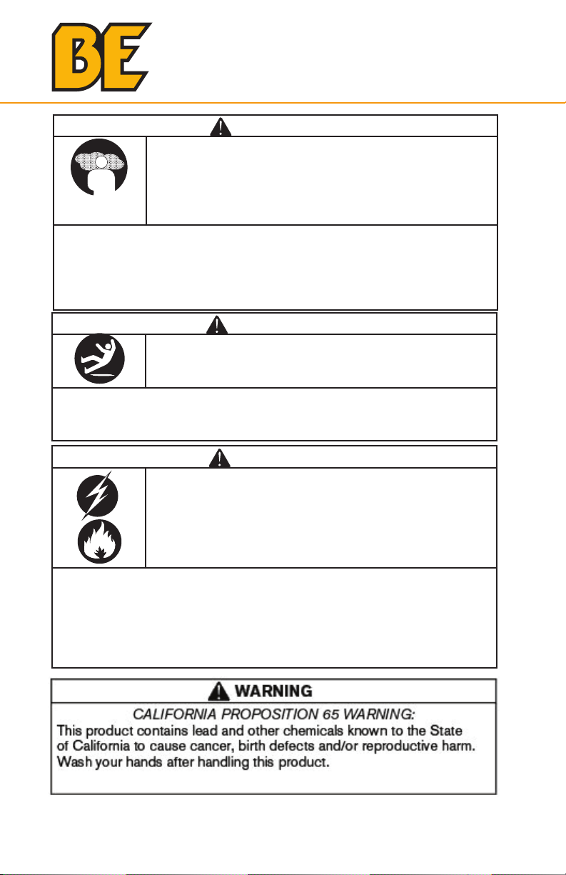
BE WP1015 User manual

WATER PUMP
WP1015
USER MANUAL

2
Introduction
3 Using the Operators Manual
Product Identification
4 Water Pump
Safety
5 Safety Rules & Warnings
5 Hazard Symbols & Meanings
Assembly
10 Connecting Hose to Pump
11 Attaching Suction Hose to Strainer Basket
11 Connecting Discharge Hose
Operation
12 What is “Head”
13 Moving the Water Pump to a Safe Location
13 Priming the Water Pump
14 Placing the Strainer Basket in Water Source
Starting The Water Pump
15 Starting the Pump & First-Time Use
Stopping The Water Pump
17 Stopping the Water Pump
17 Draining & Flushing the Water Pump
Warranty
18 Warranty
19 Claims
TABLE OF CONTENTS

3
Using the Operator’s manual
The operating manual is an important part of your water pump
and should be read thoroughly before initial use, and referred to
often to make sure adequate safety and service concerns are being
addressed.
Reading the owner’s manual thoroughly will help avoid any personal
injury or damage to your machine. By knowing how best to operate
this machine you will be better positioned to show others who may
also operate the unit.
This manual contains information for the complete range of water
pumps, and is placed in order starting from the safety requirements
to the operating functions of your machine. You can refer back to
the manual at any time to help troubleshoot any specific operating
functions, so store it with the machine at all times.
Attention: Read through the complete
manual prior to the initial use of your
water pump
INTRODUCTION

4
INTRODUCTION PRODUCT IDENTIFICATION
Using the Operator’s manual
The operating manual is an important part of your generator. It should
be read thoroughly before initial use, and referred to often to make sure
adequate safety and service concerns are being addressed.
Reading the owner’s manual thoroughly will help avoid any personal injury
or damage to your machine. By knowing how best to operate this
machine you will be better positioned to show others who may also
operate the unit.
This manual contains information for the complete range of BE
generators, and was written to take you from the safety requirements
to the operating functions of your machine. You can refer back to the
manual at any time to help troubleshoot any specific operating functions,
so store it with the machine at all times.
If you need to contact an Authorized Dealer or Customer Service line
for information on servicing, always provide the product model and
identification numbers.
You will need to locate the model and serial number for the machine and
record the information in the places provided below.
For information on warranty and to register your product online,
please visit BEPOWEREQUIPMENT.COM
Date of Purchase:
Dealer Name:
Dealer Phone:
Product Identification Numbers
Model Number:
Serial Number:
Attention: Read through the complete
manual prior to the initial use of your
generator.

5
The safety alert symbol is used with a signal word (DANGER,
CAUTION, WARNING), a pictorial and/or a safety message to alert
you to hazards.
DANGER indicates a hazard which, if not avoided, will result
in death or serious injury.
WARNING indicates a hazard which, if not avoided, could
result in death or serious injury.
CAUTION indicates a hazard which, if not avoided, might
result in minor or moderate injury.
NOTICE indicates a situation that could result in equipment
damage.
Hazard Symbols and Meanings
Save these Instructions
Safety Rules
This is the safety alert symbol. It is used to alert
you to potential personal injury hazards. Obey
all safety messages that follow this symbol to
avoid possible injury or death.
explosion
kickback
moving parts read manual
hot surface
slippery
fire electric shock
toxic fumes
SAFETY

6
WARNING
Running engine gives o carbon monoxide, an
odorless, colorless, poison gas.
Breathing carbon monoxide can cause headache,
fatigue, dizziness, vomiting, confusion, seizures,
nausea, fainting or death.
• Operate water pump ONLY outdoors.
• Keep exhaust gas from entering a confined area through windows,
doors, ventilation intakes, or other openings.
• DO NOT start or run engine indoors or in an enclosed area, even if
windows and doors are open.
WARNING
Use of water pump can create puddles and
slippery surfaces.
• Operate water pump from a stable surface.
• The area should have adequate slopes and drainage to reduce the
possibility of a fall due to slippery surfaces.
WARNING
Unintentional sparking can result in fire or electric
shock.
When Adjusting or Making Repairs to Your Water Pump
• Disconnect the spark plug wire from the spark plug and place the
wire where it cannot contact spark plug.
When Testing for Engine Spark
• Use approved spark plug tester.
• DO NOT check for spark with spark plug removed.
SAFETY

7
WARNING
Fuel and its vapors are extremely flammable and
explosive.
Fire or explosion can cause severe burns or death.
When Adding or Draining Fuel
• Turn water pump OFF and let it cool at least 2 minutes before
removing fuel cap. Loosen cap slowly to relieve pressure in tank.
• Fill or drain fuel tank outdoors.
• DO NOT overfill tank. Allow space for fuel expansion.
• If fuel spills, wait until it evaporates before starting engine.
• Keep fuel away from sparks, open flames, pilot lights, heat, and
other ignition sources.
• DO NOT light a cigarette or smoke.
When Starting Equipment
• Ensure spark plug, muer, fuel cap, and air cleaner are in place.
• DO NOT crank engine with spark plug removed.
When Operating Equipment
• DO NOT pump flammable liquids, such as fuel or fuel oils.
• This water pump is not for use in mobile equipment or marine
applications.
• DO NOT tip engine or equipment at angle which causes fuel to
spill.
• Secure water pump. Loads from hoses may cause tipover.
When Transporting or Repairing Equipment
• Transport/repair with fuel tank EMPTY or with fuel shuto valve
OFF.
• Disconnect spark plug wire.
When Storing Fuel or Equipment with Fuel in Tank
• Store away from furnaces, stoves, water heaters, clothes dryers, or
other appliances that have pilot light or other ignition source
because they can ignite fuel vapors.
SAFETY

8
WARNING
Starter cord kickback (rapid retraction) can result in
bodily injury. Kickback will pull hand and arm toward
engine faster than you can let go.
Broken bones, fractures, bruises, or sprains could
result.
Keep hands and body clear from discharge of pump.
• When starting engine, pull cord slowly until resistance is felt and
then pull rapidly to avoid kickback.
• Secure discharge hose to avoid whipping.
WARNING
Contact with muer area can result in serious burns.
Exhaust heat/gases can ignite combustibles,
structures or damage fuel tank causing a fire.
• DO NOT touch hot parts and AVOID hot exhaust gases.
• Allow equipment to cool before touching.
• Keep at least 5 feet (1.5 m) of clearance on all sides of pressure
washer including overhead.
WARNING
Starter and other rotating parts can entangle hands,
hair, clothing, or accessories.
• NEVER place hands or body parts inside of running pump or
hoses.
• Never operate water pump without protective housing or covers.
• DO NOT wear loose clothing or anything that may be caught in
the starter or other rotating parts.
• Tie up long hair and remove jewelry.
SAFETY

9
CAUTION
Excessively high operating speeds increase risk of injury and damage to
water pump.
Excessively low speeds impose a heavy load.
• DO NOT tamper with the governed speed.
• DO NOT modify the water pump.
• DO NOT allow unqualified persons or children to operate or service
water pump.
NOTICE
Improper treatment of water pump can damage it and shorten its life.
• If you have questions about intended use, ask dealer or contact
nearest authorized dealer.
• Be sure pump chamber is filled with water before starting the engine.
Never run pump without priming.
• Use a non-collapseable hose on the suction side of the hose.
• Use water pump only for intended uses.
• Pumping sea water, beverages, acids, chemical solutions, or any other
liquid that promotes corrosion can damage the pump.
• Ensure all connections are air tight.
• DO NOT obstruct the suction or discharge hose in any way.
• NEVER operate pump without strainer basket connected to end of
suction hose.
• NEVER allow vehicles to drive over hoses. If a hose must be
positioned across a roadway, use planking on each side of hose to
allow vehicles to pass over without obstructing or collapsing hose.
• Anchor pump to avoid equipment movement.
• Keep equipment away from edge of river or lake where it could cause
the bank to collapse.
• DO NOT insert any objects through cooling slots.
• NEVER operate units with broken or missing parts, or without
protective housing or covers.
• DO NOT by-pass any safety device on this machine.
• NEVER move machine by pulling on hoses. Use frame on unit.
• Check fuel system for leaks or signs of deterioration, such as chafed
or spongy hose, loose or missing clamps, or damaged tank or cap.
Correct all defects before operating water pump.
SAFETY

10
9
3. Slide hose clamp (A) over end of hose (B). Slide
suction hose onto hose barb (C). Tighten hose clamp
securely using a standard 1/4” (6mm) screwdriver.
Attach Suction Hose to Strainer Basket
Slide hose clamp over hose. Attach open end of suction hose
to strainer hose barb. Tighten hose clamp securely using a
standard 1/4” (6mm) screwdriver.
Connect Discharge Hose (Optional)
If desired, use a commercially available hose. DO NOT use a
hose with an inside diameter smaller than the pump’s
discharge port size.
1. Slide barb cuff over hose barb. Insert rubber seal into
end of barb cuff as shown earler.
2. Screw hose barb assembly onto pump in clockwise
rotation until hose barb assembly is tightened securely.
3. Slide hose clamp over end of discharge hose. Slide
discharge hose onto hose barb. Tighten hose clamp
securely using a standard 1/4” (6mm) screwdriver.
C
A
B
Your water pump requires some set up and is ready for use after it has
been properly serviced with the recommended oil and fuel.
Attach Suction Hose to Strainer Basket
1. Slide hose clamp over hose. Attach open end of suction hose to
strainer hose barb. Tighten hose clamp securely.
ASSEMBLY

11
ASSEMBLY
Connect Discharge Hose (Optional)
If desired, use a commercially available hose. DO NOT use a hose with
an inside diameter smaller than the pump’s discharge port size.
ASSEMBLY
Connect Suction Hose (Mandatory)
Attach Suction Hose by connecting camlocks.

12
What is “Head”
Head refers to the height of a column of water that can be delivered by
the discharge of the pump.
Suction Head is the vertical distance between the center of the pump
and the surface of the liquid on the suction side of the pump. May also
be referred to as “suction lift”. The atmospheric pressure of 14.7 psi at
sea level limits suction head lift to less than approximately 26 feet for any
pump.
Discharge Head is the vertical distance between the pump’s discharge
port and the point of discharge, which is the liquid surface if the hose is
submerged or pumping into the bottom of a tank.
Total Head is the sum of the suction head value plus the discharge head
value.
As water pumping height increases, pump output decreases. The length,
type, and size of the suction and discharge hoses can also significantly
aect pump output.
It is important for the suction operation to be the shorter part of the total
pumping action. This will decrease the priming time and improve pump
performance by increasing the discharge head.
Suction head is a maximum of 25 feet and discharge head should be a
maximum of 81 feet. Total head can not be more than 106 feet as shown
on next page.
Move Water Pump to Safe Operating Location
For best pump performance, locate the pump on a flat, level surface as
close as possible to the water to be pumped. Secure water pump to avoid
tipover. Use hoses that are no longer than necessary.
IMPORTANT: Direct open end of discharge hose away from home,
electrical devices or anything not desired to get wet.
WARNING
Fuel and its vapors are extremely flammable and
explosive.
Fire or explosion can cause severe burns or death.
• This water pump is not for use in mobile equipment or marine
applications
• DO NOT tip engine or equipment at angle which causes fuel to spill.
• Secure water pump. Loads from hoses may cause tip over.
OPERATION

13
OPERATION
Discharge
Head
Total
Head
Suction
Head
Prime the Water Pump
1. Remove priming plug from top of pump.
2. Fill pump with clean, clear water up to top of discharge outlet.
3. Replace priming plug.
NOTICE
Improper treatment of water pump can damage it and shorten its
life.
• Be sure chamber is filled with water before starting the engine.
• NEVER run pump without priming
OPERATION

14
Placing Strainer Basket Into Water Source
Place strainer basket into water to be pumped. Basket must be fully
immersed.
NOTICE
Improper treatment of water pump can damage it and shorten its
life.
• NEVER operate pump without strainer connected to end of suc-
tion hose.
• Keep strainer out of sand or silt, place in bucket or on stones.
• DO NOT let pump run dry or damage to seals may result.
OPERATION

15
Starting the Water Pump
Use the following start instructions:
1. Fill Engine with Oil, SAE 10W30
2. Make sure unit is on a flat, level surface and pump is primed.
3. Turn fuel valve (1) to “On” position. The fuel valve handle will be
vertical (pointing toward the ground).
4. Push on/o switch (2) to “On” position.
5. Move engine speed lever (3) to “Fast” ( ) position.
7. Grasp recoil handle and pull slowly until slight resistance is felt.
Then pull handle rapidly to overcome compression, prevent kickback
and start engine.
6. Move choke lever (4) to “On” position.
2
3
4
1
WARNING
Starter cord kickback (rapid retraction) can result in
bodily injury. Kickback will pull hand and arm toward
engine faster than you can let go.
Broken bones, fractures, bruises, or sprains could
result.
• When starting engine, pull cord slowly until resistance is felt and
then pull rapidly to avoid kickback.
STARTING THE WATER PUMP

16
IMPORTANT: If excessive fuel is present in the air/fuel mixture caus-
ing a “flooded” condition, move choke lever to “Run” position and
pull handle repeatedly until engine starts.
8. Move choke lever to “Run” position a short distance at a time over
several seconds in warm weather or minutes in cold weather. Let
engine run smoothly before each change. Operate with choke in
“Run” position.
IMPORTANT: It may take a few minutes for water pump to begin
pumping water.
WARNING
Contact with muer area can result in serious burns.
Exhaust heat/gases can ignite combustibles, struc-
tures or damage fuel tank causing a fire.
• DO NOT touch hot parts and AVOID hot exhaust gases.
• Allow equipment to cool before touching.
• Keep at least 5 feet (1.5 m) of clearance on all sides of pressure
washer including overhead.
Pump output is controlled by adjusting engine speed. Moving the
engine speed lever in the “Fast” direction will increase pump output,
and moving the engine speed lever in the “Slow” direction will
decrease pump output.
STARTING THE WATER PUMP

17
WARNING
Backfire, fire or engine damage could occur.
• DO NOT stop engine by moving choke control to “Choke”
position.
Stopping the Water Pump
1. Move engine speed lever to “Slow” position.
2. Push on/o switch to “O” position.
3. Turn fuel valve to “O” position.
Drain and Flush Water Pump
1. Disconnect and drain suction and discharge hoses.
2. Remove drain plug at bottom of pump.
3. Remove primer plug from top of pump and flush internal compo-
nents of pump with clean water.
4. Replace both plugs and finger tighten.
STOPPING THE WATER PUMP

18
WARRANTY
BE Pressure Inc. warrants that each new product will be free of any
manufacturer defects in workmanship for the set warranty period of
the product. Warranty applies to the original purchaser of the
product and cannot be transferred.
This warranty does not cover normal wear items, including but not
limited to: seals, packings, valves, o-rings, spark plugs etc. Warranty
does not include normal maintenance like oil changes, filters or valve
adjustments. Nor does it include misuse of product. Warranty
approval is at the sole discretion of BE Pressure Inc.
In no event shall BE Pressure Inc be liable for any indirect, incidental
or consequential damages from the sale or use of the product. This
disclaimer applies both during and after the term of this warranty. BE
Pressure Inc disclaims liability for any implied warranties,
including implied warranties of merchantability and fitness for a
specific purpose, after the applicable term of this warranty.

19
WARRANTY
Warranty Claim Submission
When there is a perceived fault with a product please provide the
following information to BE Pressure Inc
i. Dealer Information (Contact name and number)
ii. Product Model Number, and Serial Number (hour reading of
machines with hour meter, or estimate of hours)
iii. Electronic Copy of Customer Invoice
iv. Explanation of defect or how it is not performing properly
a.Trouble shooting steps already taken
v. Pictures of product including
a. Picture of whole unit showing condition
b. Picture of serial number
c. In close of picture of problem area (leaking oil, water,
broken part, etc)
For more information on warranty and returns,
please visit the support section at:
BEPOWEREQUIPMENT
.COM
or call 1-800-663-8331.

If you need assistance with the assembly
or operation of your Water Pump please call
1-866-850-6662
THE POWER YOU NEED.
Table of contents
Other BE Water Pump manuals
Popular Water Pump manuals by other brands

Everbilt
Everbilt SP03302VD Use and care guide

Bijur Delimon
Bijur Delimon DP33 manual

SANICONDENS
SANICONDENS Best Flat 190 Operating & installation manual

hillvert
hillvert HT-SP-104 user manual

Anest Iwata
Anest Iwata ISP-250C Series instruction manual

Harbor Freight Tools
Harbor Freight Tools creekstone 63402 owner's manual