BEA UL MAGLOCKS 600LB User manual

75.5366.08 UL MAGLOCKS 600lb 20210806 Page 1 of 4
UL MAGLOCKS 600LB
USER’S GUIDE
ELECTROMAGNETIC LOCKS
The Electromagnetic Lock (Maglock) series is a surface-mounted,
magnetic-lock assembly. They are available in single- and dual-
lock varieties, various holding forces, and also avaible with or
without built-in Door Status Switch (“DS” versions). All models
are designed for standard installation on most types of doors.
Door Position
Switch
ENGLISH
door conguration door status sensor
single dual with without
10MAGLOCK3UL
10MAGLOCK3ULDS
10MAGLOCK6UL
10MAGLOCK6ULDS
1 Description
DESCRIPTION 10MAGLOCK3UL
10MAGLOCK3ULDS
10MAGLOCK6UL
10MAGLOCK6ULDS
Lock: single dual
Input Voltage: 12 or 24 VDC 12 or 24 VDC
Relay Rating: 1.0 A @ 24 VDC
resistive
1.0 A @ 24 VDC
resistive
Reed Switch Rating: SPDT 0.5 amp @ 30 VAC/VDC
resistive
SPDT 0.5 amp @ 30 VAC/VDC
resistive
Power Consumption: 505 mA @ 12 VDC /
260 mA @ 24 VDC
505 ×2 mA @ 12 VDC /
260 ×2 mA @ 24 VDC
Dimensions: 9.84 x 1.65 x 1.02 in
250 x 42 x 26 mm
19.76 x 1.65 x 1.02 in
502 x 42 x 26 mm
Certication: UL1034 UL1034
Operating Temperature: 14 – 131 °F (-10 – 55 °C) 14 – 131 °F (-10 – 55 °C)
Operating Humidity: 0 – 95% 0 – 95%
ATTENTION: This product must be powered from a UL-listed, regulated, power-limited, power supply!
NOTE: The specications listed above are for an indoor, dry, installation location.
2 Specications

FOLD ON DOTTED LINE
(1/8")
DRILL 3.2mm HOLE
(2 PLACES)
PLACE AGAINST DOOR
(11/16")
DRILL 16mm HOLE
TEMPLATE
PLACE AGAINST JAMB
OPPOSITE HINGES FOR
L.H.R. DOOR INSTALLATION
PLACE AGAINST HEADER
185mm ARMATURE PLATE GUIDE PIN HOLE
[6mm(1/4") DIA, 12.5mm(1/2") DEEP]
185mm ARMATURE PLATE
[6mm(1/4") DIA, 12.5mm(1/2") DEEP]
PLACE AGAINST JAMB
OPPOSITE HINGES FOR
R.H.R. DOOR INSTALLATION
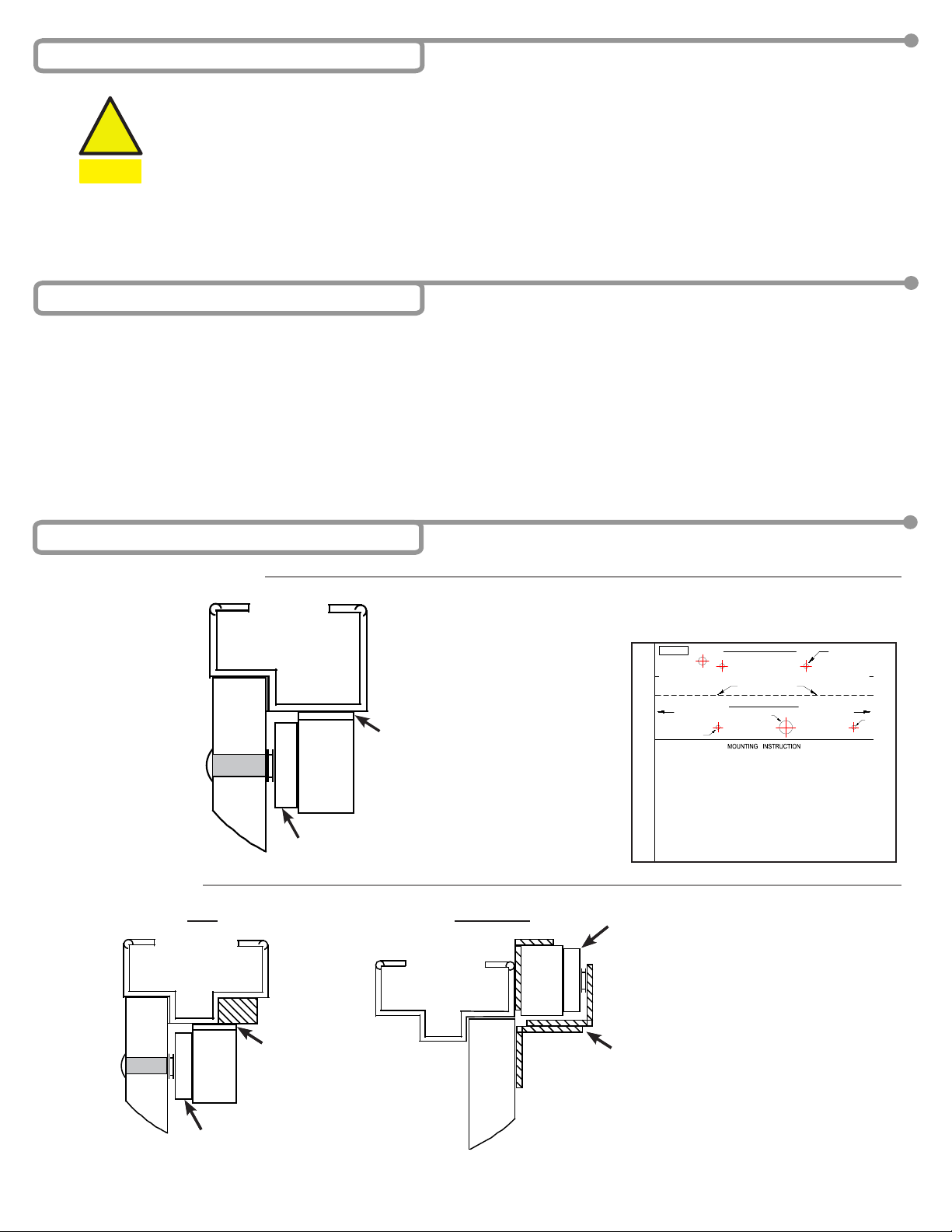
STEP 1
FOLD TEMPLATE ALONG DOTTED LINE.
PLACE TEMPLATE AGAINST DOOR AND HEAD FRAME.
DRILL HOLES AS INDICATED ON TEMPLATE.
STEP 2
MOUNT THE ARMATURE PLATE TO DOOR USING
1 RUBBER WASHER SANDWICHED BETWEEN 2 STEEL
WASHER (THE RUBBER WASHER AND 2 STEEL
WASHER ARE INSTALLED ON THE THROUGH SEXNUT
BETWEEN THE ARMATURE PLATE AND DOOR).
●
●
●
●
STEP 3
DETACH MOUNTING PLATE FROM MAGNET BY REMOVING
2 SOCKET CAP SCREWS. SCREWS COULD BE ACCESSED
THROUGH BOTTOM OF MAGNET.
●
●INSTALL THE MOUNTING PLATE WITH 2 FLAT HEAD
SCREWS (THE 2 M5x15 FLAT HEAD SCREWS ARE
INSTALLED IN THE SLOTTED HOLES FOR ADJUSTMENT).
ADJUST MOUNTING PLATE SO THAT IT FORMS A RIGHT
ANGLE WITH THE ARMATURE PLATE.
●
●USING THE MOUNTING PLATE AS A TEMPLATE,DRILL
THE WIRE HOLE.
●DRILL AND INSTALL THE REMAINING MOUNTING SCREWS.
STEP 4
INSTALL MAGNET TO MOUNTING PLATE WITH
2 M6 SCREWS SUPPLIED.
●
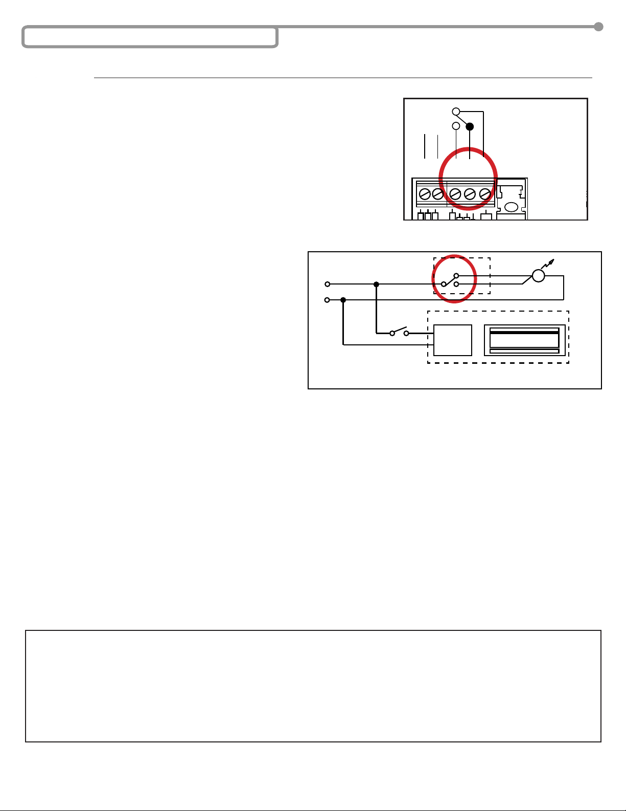
INSTALL ELECTRICAL WIRING PER
INSTRUCTION SHEET.
●
STEP 5
TEST ALL FUNCTIONS OF THIS MODEL (SEE
WIRING INSTRUCTION).
●
STEP 6
INSERT 2 LOCKING STOPPERS IN TWO END
PLATES,AND COVER WITH 4 mm SCREWS.
●
STEP 7
INSERT 2 ALUMINUM CAPS TO COVER THE
TWO M6 SCREW HOLES.
●
STEP 8
NOTE: IF NEEDED, USE SMALL MAGNET TO
REMOVE LOCKING STOPPERS FROM HOLES.
●
DWG. NO. 820001
Page 2 of 4 75.5366.08 UL MAGLOCKS 600lb 20210806
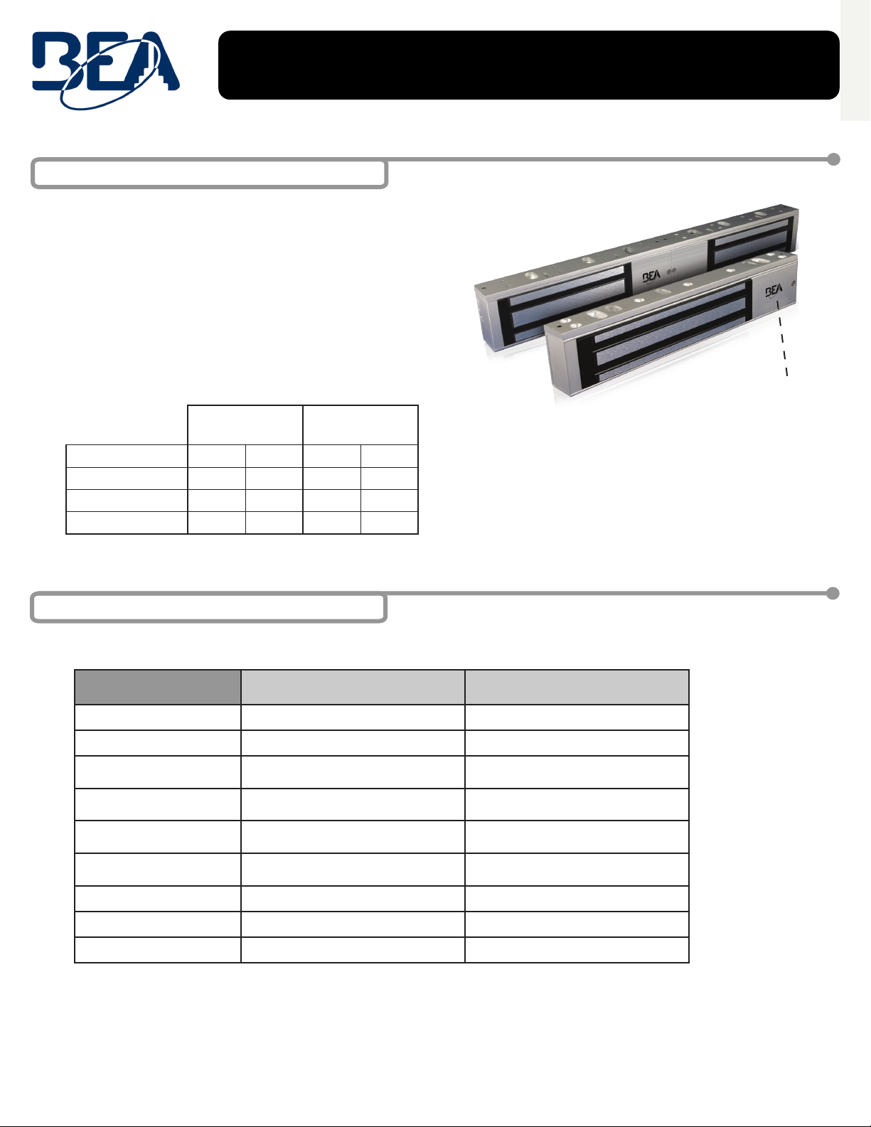
5Handle the equipment with care. Damaging the mating surfaces of the magnet and armature plate may reduce locking efciency.
5The maglock mounts rigidly to the door frame. The armature plate mounts to the door with the hardware provided. This allows
the armature plate to pivot about its center to compensate for door wear and misalignment.
5Template use must take place with the door in its normally closed position.
5Add threadlocker to all screws before installing, and rmly tighten screws.
5Install only for indoor, dry applications.
5Installation and wiring must be performed in compliance with ANSI/NFPA70 regulations.
5The Maglock shall be installed within the same room as other equipment and circuitry connecting to the Maglock (per UL 864).
5Shut off all power going to door or header before attempting any wiring procedures.
5Maintain a clean and safe environment when working in public areas.
5Constantly be aware of pedestrian trafc around the door area.
5Always stop pedestrian trafc through the doorway when performing tests that may result in unexpected reactions
by the door.
5Always check placement of all wiring before powering up to ensure that moving door parts will not catch any wires
and cause damage to equipment or cable insulation.
5Ensure compliance with all applicable safety standards (i.e. ANSI A156.10) upon completion of installation.
DO NOT over-tighten the armature plate.
The rubber washer is designed to allow the armature plate to automatically adjust position for best mating position between the magnet and armature plate.
DOOR FRAME
DOOR FRAME
DOOR FRAME
MAGNET
MAGNET
MAGNET
DOOR
DOOR
DOOR
MOUNTING PLATE
Use the applicable mounting template.
See image of template below.
See User’s Guide 75.5643 for U-bracket
installation (to be used with glass doors).
MOUNTING PLATE L&Z BRACKET
FILLER
ARMATURE PLATE
ARMATURE PLATE
ARMATURE PLATE
Filler L&Z bracket
3 Precautions
4 Installation Notes
5 Installation – Mechanical
Mounting Options
TYPICAL INSTALLATION
!
CAUTION

!
CAUTION
Page 2 of 2 75.5366.02 20140401
5 Installation - Mechanical & Electrical
LOCK STATUS SWITCH (SPDT)
POWER
SUPPLY
+ -
POWER
SELECTOR
JUMPER
LED
MAG BOND SENSOR
MAGNET
TIMER (0-90 SEC)
TYPICAL INSTALLATION
NOTE: DO NOT over-tighten the armature plate. The rubber washer is designed to allow the armature
plate to automatically adjust position for best mating position between the lock and armature plate.
DOOR FRAME
ARMATURE PLATE
MAGNET
ANGLE
BRACKET
MOUNTING
PLATE
MOUNTING
PLATE
STRINGER
HOLE FOR
GUIDE PIN
HOLE FOR NUT
RUBBER WASHER
STEEL WASHER
ARMATURE PLATE
SCREW M8 (35MM)
GUIDE PIN
DOOR
NUT
SPACER
WASHER
ARMATURE
PLATE
DOOR
NUT
DOOR FRAME DOOR FRAME
DOOR
ARMATURE PLATE ARMATURE PLATE
MAGNET MAGNET
DOOR DOOR
MOUNTING
PLATE
CAUTION: Observe proper
circuit board orientation!
NOTE: The product must be powered from a UL listed, regulated, power limited, power supply.
NOTE: If power switch is not wired between DC source voltage and magnet,
it will take a longer time to de-energize the magnet simulating residual magnetism.
1. 12 VDC INPUT
A. Required power 0.5A (Max).
B. Connect ground (-) lead from a 12 VDC power source to Terminal 2.
C. Connect positive (+) lead from a 12 VDC power source to Terminal 1.
D. Check jumper for 12 VDC operation.
2. 24 VDC INPUT
A. Required power 0.25A (Max).
B. Connect ground (-) lead from a 24 VDC power source to Terminal 2.
C. Connect positive (+) lead from a 24 VDC power source to Terminal 1.
D. Check jumper for 24 VDC operation.
3. CONTACTS
1. Relay dry contacts are rated 1A at 24 VDC for safe operation, DO NOT exceed this
rating.
2. If a NO switch is required, connect the wires from the system to Terminal 4 & Terminal 3.
3. If a NC switch is required, connect the wires from the system to Terminal 4 & Terminal 5.
DS VERSION
24/7 Tech Support: 1-800-407-4545 | Customer Service: 1-800-523-2462 | General Tech Questions: T[email protected] | Tech Docs: www.beasensors.com
75.5366.08 UL MAGLOCKS 600lb 20210806 Page 3 of 4
CIRCUIT BOARD
NOTE: Terminals ratings: 12~24AWG
7 Installation – Electrical
CAUTION! Observe
proper circuit board
orientation!
+ -
G
1 2 3 4 5
+ - NO C NC
12VDC
24VDC
POWER
SELECTOR
JUMPER
0 - 90 SEC.
RELOCK TIMER
POWER
SUPPLY
+ -
LOCK STATUS RELAY (SPDT)
Align the black, plastic piece of the
armature plate with the cover plate (i.e.
magnet must line up with the switch).
6 Armature Plate Installation
Hole For Guide Pin
Hole For Nut
Steel Washer
Rubber Washer
Steel Washer
Armature Plate
Nut
Spacer
Door
Screw M8 35mm
Guide Pin
The product must be powered from a UL-listed, regulated, power-limited, power supply.
If power switch is not wired between DC source voltage(+) and magnet, it will take a longer time
to de-energize the magnet simulating residual magnetism.
Dual MAGLOCK models have two circuit boards that must both be powered; repeat these steps
on each side.
12 VDC INPUT
- Required power: See Specications on page 2.
- Connect positive (+) lead from a 12 VDC power source to Terminal 1.
- Connect negative (-) lead from a 12 VDC power source to Terminal 2.
- Check jumper for 12 VDC operation.
24 VDC INPUT
- Required power: See Specications on page 2.
- Connect positive (+) lead from a 24 VDC power source to Terminal 1.
- Connect negative (-) lead from a 24 VDC power source to Terminal 2.
- Check jumper for 24 VDC operation.
+ -
G
1 2 3 4 5
+ - NO C NC
12VDC
24VDC
POWER
SELECTOR
JUMPER
0 - 90 SEC.
RELOCK TIMER
POWER
SUPPLY
+ -
LOCK STATUS RELAY (SPDT)
POWER

Page 4 of 4 75.5366.08 UL MAGLOCKS 600lb 20210806
LOCK STATUS RELAY CONTACTS (SPDT)
- Relay dry contacts are rated 1A at 24 VDC for safe operation, DO NOT exceed this
rating.
- If a NO switch is required, connect the wires from the system to Terminal 3 and
Terminal 4.
- If a NC switch is required, connect the wires from the system to Terminal 4 and
Terminal 5.
DOOR STATUS SWITCH (DS versions only)
- Connect the positive (+) lead from the power source to the
black wire of the Door Status Sensor switch.
- Connect the negative (-) lead from the power source to one
end of the light for door status.
- Connect the red or green wire of the Door Status Sensor switch
to the other end of the light for door status.
red = light off with door closed
green = light on with door closed
- Reed switch dry contacts are rated 0.25 amp at 30 VAC/VDC
for safe operation. Do not exceed this rating.
7 Installation – Electrical (cont.)
SWITCHES
+ -
G
1 2 3 4 5
+ - NO C NC
12VDC
24VDC
POWER
SELECTOR
JUMPER
0 - 90 SEC.
RELOCK TIMER
POWER
SUPPLY
+ -
LOCK STATUS RELAY (SPDT)
1
PCB
2
sw
+
-
NC
COM NO
1
PCB
2
MAGNETIC LOCK
NC RED
GREEN
BLACK
LIGHT
COM
REED SWITCH
ON
DOOR STATUS SENSOR SWITCH*
* Switch changes state when door is open
NO
BEA Inc., the sensor manufacturer, cannot be held responsible for incorrect installations or incorrect adjustments of the sensor/device; therefore, BEA Inc. does not
guarantee any use of the sensor/device outside its intended purpose.
BEA Inc. strongly recommends that installation and service technicians be AAADM-certified for pedestrian doors, IDA-certified for doors/gates, and factory-trained for the
type of door/gate system.
Installers and service personnel are responsible for executing a risk assessment following each installation/service performed, ensuring that the sensor/device system
performance is compliant with local, national, and international regulations, codes, and standards.
Once installation or service work is complete, a safety inspection of the system shall be performed and documented per the manufacturer’s recommendations or industry
guidelines. Examples of compliance may apply to ANSI 156.10, ANSI 156.19, ANSI/DASMA 102, ANSI/DASMA 107, UL294, UL325, and International Building Code.
BEA, INC. INSTALLATION/SERVICE COMPLIANCE EXPECTATIONS
Tech Support & Customer Service: 1-800-523-2462 | General Tech Questions: [email protected] | Tech Docs: www.BEAsensors.com
This manual suits for next models
4
Other BEA Lock manuals
Popular Lock manuals by other brands

National Cabinet Lock
National Cabinet Lock C8711 Dimensional drawing

ANXELL
ANXELL ML-400M Installation instruction

SECO-LARM
SECO-LARM E-941SA-1K2PD installation manual

Dorma
Dorma ARCOS Office Mounting instructions

Borglocks
Borglocks BL2605MG Installation Guide, Parts List & Maintenance Instructions

Assa Abloy
Assa Abloy APERIO P100 Setup instructions

nvent
nvent CADDY Speed Link SLS Series Technical handbook

Burg Wächter
Burg Wächter secuENTRY ENTRY 7710 RFID manual

Hongda USA
Hongda USA DL210 manual

Paxton
Paxton PaxLock Pro APN-1173-AE Installation and commissioning guide

KSQ
KSQ CR2450 quick start guide

Assa Abloy
Assa Abloy Sargent IN100 installation instructions