51120-G 10/2008
4
INTRODUCTION:
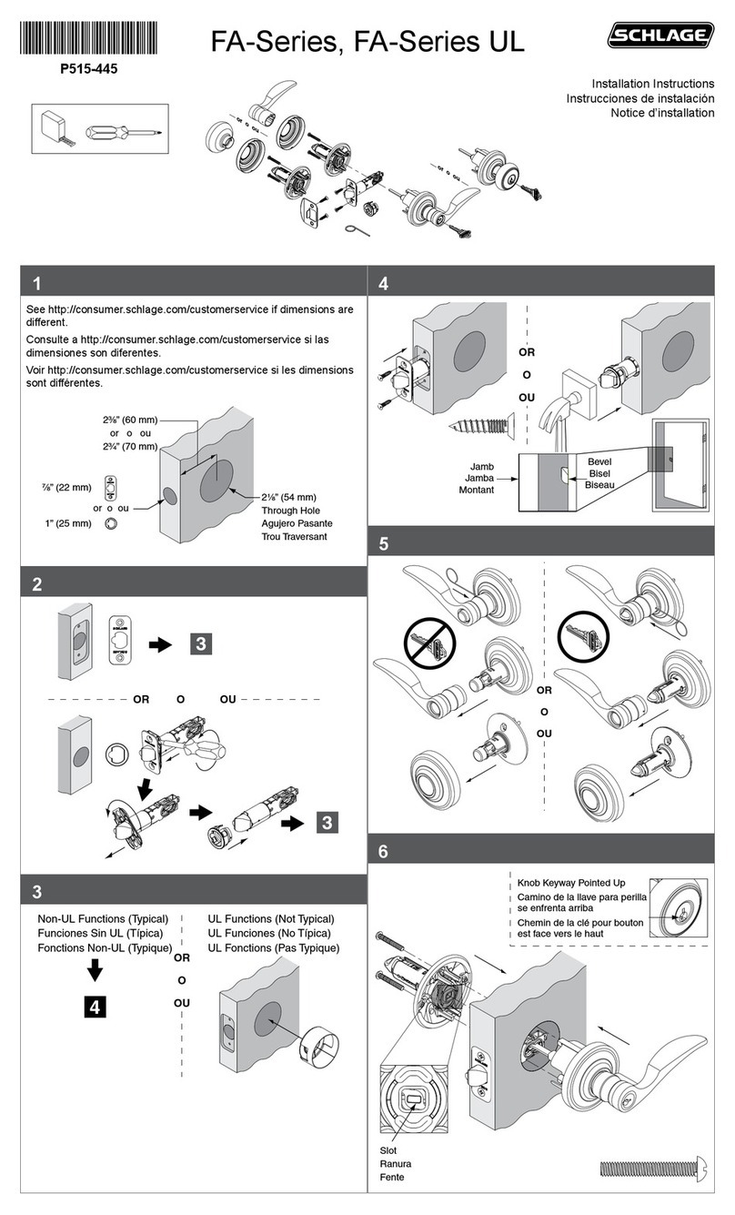
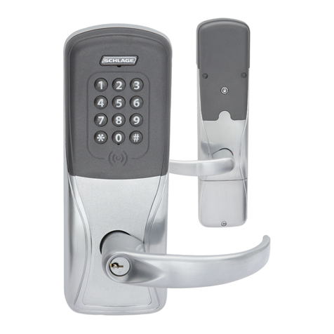
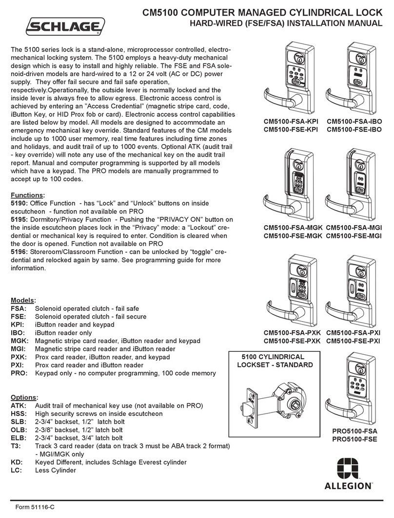
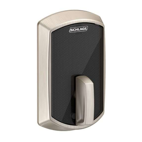
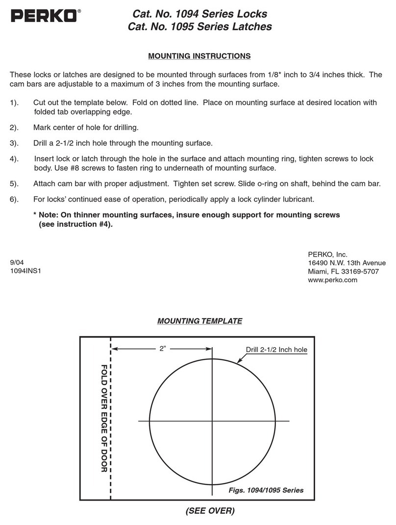
This manual covers the complete hardware installation of all models in
the WA5200 & AUWA5200 Cylindrical Series line of Wireless Access
Modular Locks.
NOTES:
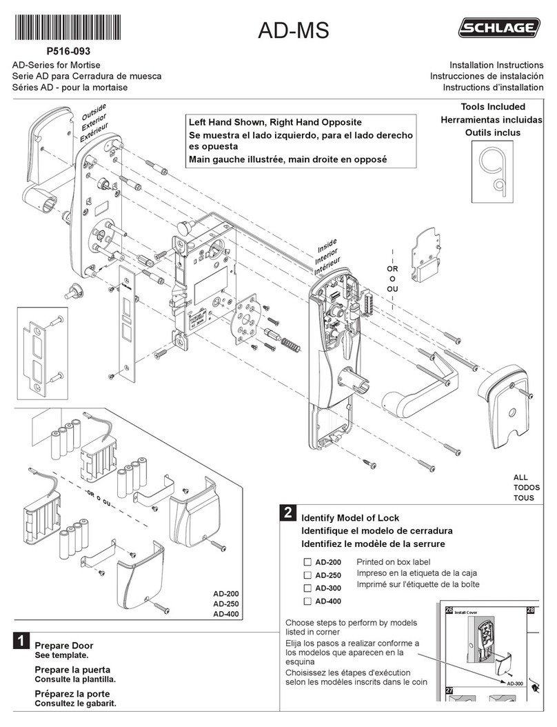
!Illustration on pages 2 and 3 shows a LH installation, but yours might be
different.
!When mounting Reader and Transceiver:
- Wear some form of ESD protection.
- Do not use power tools to tighten mount screws. Hand tools only.
- Turn in each mount screw a little bit at a time.
- Do not over tighten mount screws.
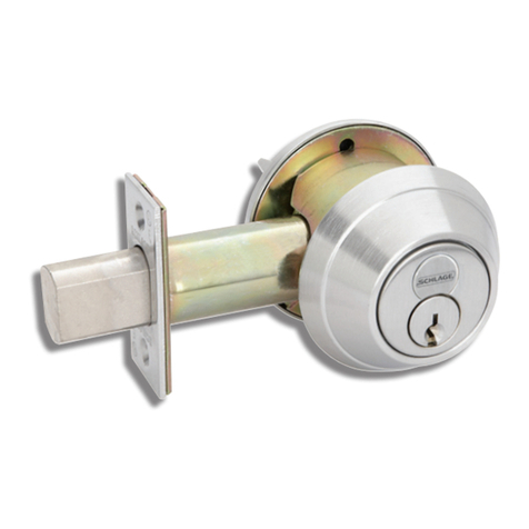
If cylinder key does not work properly, check that cylinder and appropriate
cylinder cam are installed in correct position.
NON-SUPPLIED TOOLS & MATERIALS NEEDED:
F Philips head screwdriver set
F Power Drill with 3/8"[10mm] chuck
F Drill bit set (up to 1"[25mm])
F 2-1/8"[54mm] hole saw w/mandrel
F Allen wrench set
F Square (90 degrees)
F Threadlocker (Loctite 242 recommended)
F Tape Measure
F Pencil
F Center Punch
F Hammer
F Chisel
F Masking tape
F Level
F Fire rated putty (recommend-Metacaulk Putty from Rectorseal Corp.)
4
INSTALLATION INSTRUCTIONS
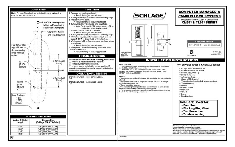
See Back Cover for:
- Door & Frame Prep
- Interchangeable Core Installation
- Tailpiece Installation
- Lock Timing: SFIC, Standard, & LFIC
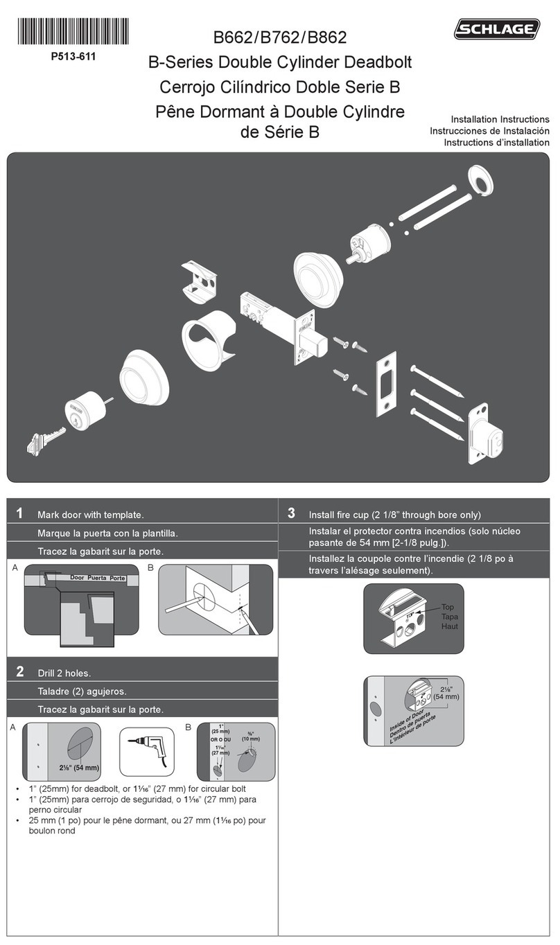
DOOR & FRAME PREP
WIRELESS ACCESS
MODULAR LOCKS
WA5200 & AUWA5200
CYLINDRICAL SERIES
OUTSIDE FRAMEDOOR EDGE
2-5/8"
(2.625")
[67mm]
INSIDE
C
LLever
5-3/4"
(5.750")
[146mm]
ø1/8"
(0.125")
[3mm]
1" Deep
[25mm]
6X
LH / LHR RH / RHR
C
L
2-3/4"
(2.750")
[70mm]
3"
(3.00")
[76mm]
2"
(2.00")
[51mm]
ø2-1/8"
(2.125")
[54mm]
THRU
ø5/16"
(0.313")
[8mm]
THRU
2X
C
LDoor
Contact
1-3/8"
(1.375")
[35mm]
1-5/8"
(1.625")
[41mm]
13/16"
(0.813")
[21mm]
2-3/4"
(2.750")
[70mm]
3/8"
(0.375")
[10mm]
3/4"
(.750")
[19mm]
1-5/16"
(1.313")
[33mm]
Top hole: For metal doors. Drill this side only.
Bottom hole: For wood doors. Drill thru.
13/16"
(0.813")
[21mm]
1-5/8"
(1.625")
[41mm]
#8-32
FH
Comb.
2X
ø1"
(1.000")
[25mm]
To intersect
2-1/8" hole.
ø3/4"
(0.750")
[19mm]
ø3/4"
(0.750")
[19mm]
To Intersect
Wire Hole
1-1/8 x 2-1/4"
(1.125 x 2.250")
[29mm x 57mm]
Depth = 3/16" (0.188") [5mm]
5-11/16"
(5.688")
[144mm]
1-1/4 x 4-7/8"
(1.250 x 4.875")
[32mm x 124mm]
Depth = 3/16" (0.188") [5mm]
15/16 x 3-5/8"
(.940 x 3.625")
[24mm x 92mm]
Depth =1- 1/8" (1.125") [29mm]
4-1/8"
(4.125")
[105mm]
#12-24
FHMS
2X
ø3/4"
(0.750")
[19mm]
Depth=2"
(2.000") [51mm]
1-1/4"
(1.250")
[32mm]
ø3/4"
(0.750")
[19mm]
11/16"
(0.688")
[17mm]
5/8"
(0.625")
[16mm]
LH / LHR RH / RHR
C
L
4"
(4.000")
[102mm]
5"
(5.000")
[127mm]
1-7/16"
(1.438")
[37mm]
ø1/8"
(0.125")
[3mm]
Depth=1" [25mm]
4X
Measure
backset
from center
of bevel.
2-3/4"
(2.750")
[70mm]
2-3/8"
(2.375")
[60mm]
C
LC
L
SFIC
(Small Format IC)
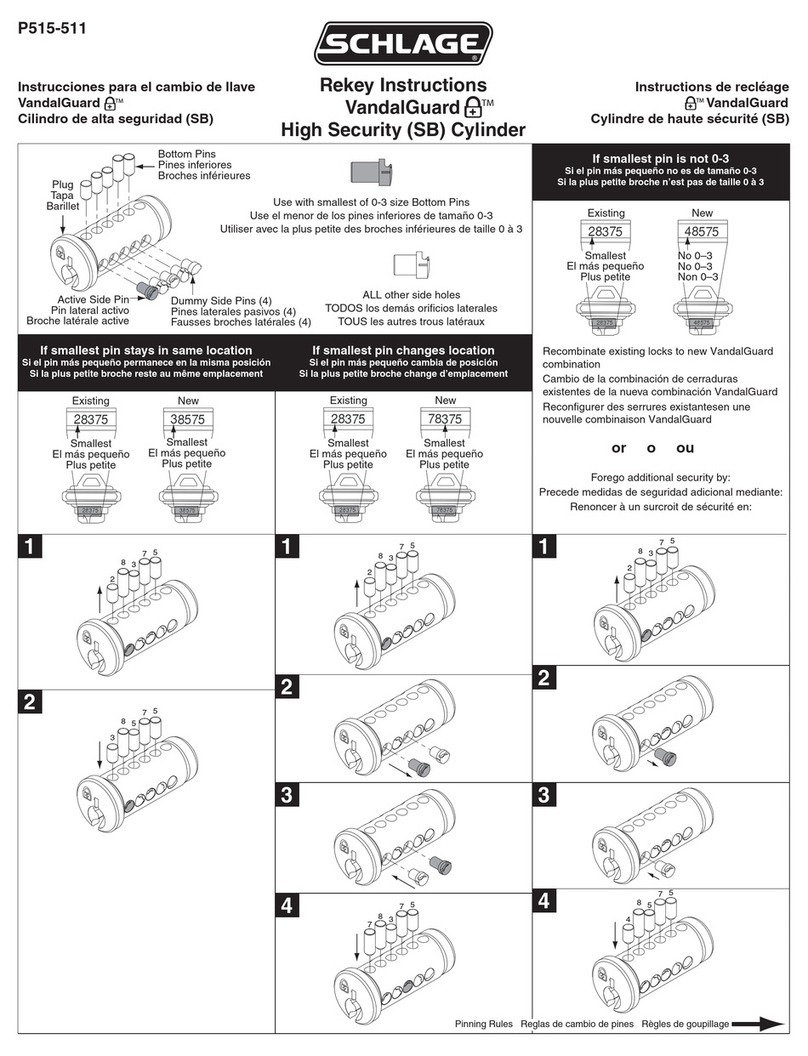
Install Interchangeable Core
FSIC: Insert key into core. Turn key 15° CW and
hold. Insert core into lever.
SFIC: Insert driver into back of core. Insert key
into core. Turn key 15° CW and hold.
Insert core into lever.
----
Install Tailpiece
(a) Remove Cyl. Cap. Depress
cap pin. Rotate cap CCW until off.
(b) Select Tailpiece. See below.
(c) Install Tailpiece. Place tailpiece
against back of cyl. Place cap over
tailpiece. Depress cap pin. Rotate
cap CW until tight.
FSIC
(Full Size IC)
b
a
a
b
c
Lock Timing- SFIC & Standard
(a) Insert key into cylinder. Rotate key
90 CW & hold.
(b) Insert push pin into lever hole.
Depress lever catch. Pull off lever.
(c) Rotate key 180 CCW. Slide lever
onto spindle.
°
°
Lock Timing - LFIC
(a) Remove core. Remove lever assembly
(refer to illustration on pages 2 and 3).
(b) Using provided driver tool, rotate driver
180° CW. Reinstall lock.
core
driver
core
15°
15°
N523-022
N523-023
a
b
c
Classic
Everest or Primus
cap pin cap
push
pin
cap
core
driver tool
(provided)
180°
90°
lever
catch
180°
FCC Compliance
s This device has been authorized by the FCC Rules and Industry Canada.
s This device complies with the limits for a Class B digital device and a
Class B intentional radiator, pursuant to Part 15 of the FCC Rules and with
RSS-210 of Industry Canada. Operation is subject to the following two
conditions: (1) This device may not cause harmful interference, and (2) this
device must accept any interference received, including interference that
may cause undesired operation.
s The Wireless Access System Component must be installed by qualified
professionals or contractors in accordance with FCC part 15.203, Antenna
Requirements.
s Do not use any antenna other than the one provided with the unit.
UL Compliance
w The WA5200 & AUWA5200 Wireless Access Cylindrical Locks are listed
under UL294 as an access control system accessory.
w The WA5200 & AUWA5200 Wireless Access Cylindrical Locks are listed
under UL10C.
w Access equipment manufactured and/or sold by Ingersoll Rand Security
Technologies is not rated for, or intended for use in life safety installations.
w For UL installations that use a Door Position Switch, use a UL listed
door/window contact. Door contacts for door position monitoring are not for
intrusion protection.
w No standby power provided.
w The WA5200's & AUWA5200's maximum current at 12 VDC is 250 mA.
Warnings
s RF Exposure - To comply with FCC RF exposure requirements for mobile
transmitting devices, this transmitter should only be used or installed at
locations where there is normally at least a 20 cm separation between the
antenna and all persons.
s Do not co-locate and operate in conjunction with any other antenna or
transmitter.
s Use only the Battery Pack specified in this instruction manual.
s Do not subject Battery Pack to fire or high temperatures.
s Do not attempt to recharge, short out or disassemble Battery Pack.
s Follow local regulations for alkaline battery disposal.
s Immediately remove the batteries and discontinue use if: the product is
impacted after which the interior is exposed, or the product emits a strange
smell, heat, or smoke.
s Changes or modifications not expressly approved by Ingersoll Rand
Security Technologies could void the user's authority to operate the
equipment.
Schlage Lock Company
575 Birch Street
Forrestville, CT 06010
technical support: 866-322-1237
web: www.irsupport.net
