Beacon/Morris PRIOM-1 Instruction manual
PRIOM-1
PANEL RADIATOR
INSTALLATION, OPERATION
& MAINTENANCE MANUAL
ATTENTION: READ THESE INSTRUCTIONS CAREFULLY BEFORE ATTEMPTING
TO INSTALL, OPERATE, OR SERVICE. RETAIN THESE INSTRUCTIONS FOR
FUTURE REFERENCE.
INSPECT THE SHIPMENT IMMEDIATELY WHEN RECEIVED TO DETERMINE IF ANY
DAMAGE HAS OCCURRED DURING SHIPMENT.
260 NORTH ELM STREET, WESTFIELD, MASSACHUSETTS 01085
7555 TRANMERE DRIVE, MISSISSAUGA, ONTARIO L5S 1L4 CANADA

2
Section 1: General Information
Important Information
Inspect Panel Radiator and all contents for damage prior to installation. There will be 2 boxes. One contains
the panel radiator and one contains necessary mounting hardware and radiator accessories. If additional
accessories were ordered, they will arrive in a 3rd box check your packing slip for more information.
Accessory Box Contents
• Insert Pack containing: 1 Valve
insert, 1 valve insert cover, 1
drain cover (see Fig. 1)
• Type 11 only - L Bracket
Installation Kit containing: 2
brackets, 4 wall anchors, 4
bolts, 1 air vent, 1 drain cover,
2 locking clips, 4 plastic U
inserts (see Fig. 2)
• Type 21/22/33 only – J Bracket
Installation Kit containing: 2
J Brackets, 4 wall anchors, 4
bolts, 1 air vent, 1 drain cover
(see Fig. 3)
Figure 1 – Insert Pack Contents
Figure 2 – L Bracket Kit
Figure 3 – J Bracket Kit
PLEASE NOTE: Any 70" (1800 mm) panel
radiator will require the installation of a
3rd bracket in the center of the unit. These
units will come with 2 brackets kits. Only 1
bracket needs to be used from the 2nd kit.

3
Section 2: Specications and Ratings
Type Part Number Depth
Dimensions (HxL) Output
(BTU)
@120°F
Output
(BTU)
@140°F
Output
(BTU)
@160°F
Output
(BTU)
@180°F
Weight
(lbs)
Water
Content
(gal)
Equivalent
Baseboard
@180°F (ft)In. mm
11
5136U1150040100
2-3/4
19 11/16 x 15 3/4 500 x 400 506 810 1,139 1,472 13 0.29 3
5136U1150060100 19 11/16 x 23 5/8 500 x 600 758 1,215 1,708 2,207 18 0.44 4
5136U1150070100 19 11/16 x 27 9/16 500 x 700 887 1,419 1,991 2,575 22 0.5 5
5136U1150090100 19 11/16 x 35 7/16 500 x 900 1,140 1,824 2,560 3,311 26 0.66 6
5136U1150100100 19 11/16 x 39 3/8 500 x 1000 1,268 2,024 2,847 3,678 29 0.73 7
5136U1160060100 23 5/8 x 23 5/8 600 x 600 922 1,490 2,093 2,731 22 0.52 5
5136U1160070100 23 5/8 x 27 9/16 600 x 700 1,081 1,737 2,444 3,189 24 0.6 6
5136U1160090100 23 5/8 x 35 7/16 600 x 900 1,389 2,237 3,145 4,104 31 0.76 8
21
5136U2640040000
2-7/8
15 3/4 x 15 3/4 400 x 400 583 927 1,280 1,654 15 0.47 3
5136U2640060000 15 3/4 x 23 5/8 400 x 600 875 1,391 1,921 2,484 22 0.71 5
5136U2640070000 15 3/4 x 27 9/16 400 x 700 1,019 1,622 2,239 2,895 26 0.84 5
5136U2640090000 15 3/4 x 35 7/16 400 x 900 1,311 2,083 2,879 3,726 33 1.08 7
5136U2640100000 15 3/4 x 39 3/8 400 x 1000 1,454 2,313 3,197 4,138 37 1.18 8
5136U2640120000 15 3/4 x 47 1/4 400 x 1200 1,749 2,778 3,841 4,968 44 1.42 9
5136U2640140000 15 3/4 x 55 1/8 400 x 1400 2,038 3,239 4,477 5,775 51 1.66 10
5136U2640180000 15 3/4 x 70 7/8 400 x 1800 2,621 4,166 5,755 7,448 64 2.16 13
5136U2650040000 19 11/16 x 15 3/4 500 x 400 699 1,114 1,558 2,002 20 0.58 4
5136U2650060000 19 11/16 x 23 5/8 500 x 600 1,047 1,674 2,340 3,009 29 0.87 6
5136U2650070000 19 11/16 x 27 9/16 500 x 700 1,223 1,951 2,730 3,507 33 1.03 7
5136U2650090000 19 11/16 x 35 7/16 500 x 900 1,570 2,507 3,508 4,511 41 1.32 8
5136U2650100000 19 11/16 x 39 3/8 500 x 1000 1,762 2,814 3,935 5,013 46 1.45 9
5136U2650140000 19 11/16 x 55 1/8 500 x 1400 2,468 3,935 5,508 6,980 53 1.58 13
5136U2650180000 19 11/16 x 70 7/8 500 x 1800 3,173 5,064 7,085 9,022 82 2.61 16
5136U2660040000 23 5/8 x 15 3/4 600 x 400 817 1,303 1,826 2,322 24 0.68 5
5136U2660060000 23 5/8 x 23 5/8 600 x 600 1,226 1,955 2,734 3,533 33 1.03 7
5136U2660070000 23 5/8 x 27 9/16 600 x 700 1,431 2,280 3,192 4,120 40 1.21 8
5136U2660090000 23 5/8 x 35 7/16 600 x 900 1,840 2,935 4,106 5,302 49 1.55 10
5136U2660100000 23 5/8 x 39 3/8 600 x 1000 2,043 3,257 4,559 5,887 55 1.71 11
5136U2660120000 23 5/8 x 47 1/4 600 x 1200 2,449 3,908 5,471 7,064 66 2.06 13
5136U2660140000 23 5/8 x 55 1/8 600 x 1400 2,861 4,564 6,386 8,206 77 2.38 15
22
5136U2230060000
4-1/8
11 13/16 x 23 5/8 300 x 600 825 1,309 1,824 2,358 20 0.55 5
5136U2230070000 11 13/16 x 27 9/16 300 x 700 962 1,526 2,130 2,750 24 0.66 5
5136U2230090000 11 13/16 x 35 7/16 300 x 900 1,237 1,966 2,739 3,542 29 0.84 7
5136U2230100000 11 13/16 x 39 3/8 300 x 1000 1,375 2,182 3,042 3,934 33 0.95 7
5136U2230120000 11 13/16 x 47 1/4 300 x 1200 1,649 2,619 3,651 4,719 37 1.13 9
5136U2230130000 11 13/16 x 51 3/16 300 x 1300 1,787 2,839 3,958 5,115 42 1.24 9
5136U2230140000 11 13/16 x 55 1/8 300 x 1400 1,924 3,056 4,260 5,491 48 1.37 10
5136U2230180000 11 13/16 x 70 7/8 300 x 1800 2,474 3,932 5,478 7,084 57 1.69 13
5136U2240040000 15 3/4 x 15 3/4 400 x 400 712 1,132 1,583 2,013 18 0.47 4
5136U2240060000 15 3/4 x 23 5/8 400 x 600 1,065 1,696 2,374 3,016 26 0.71 6
5136U2240070000 15 3/4 x 27 9/16 400 x 700 1,242 1,978 2,767 3,518 31 0.84 7
5136U2240090000 15 3/4 x 35 7/16 400 x 900 1,595 2,546 3,559 4,524 40 1.08 8
5136U2240100000 15 3/4 x 39 3/8 400 x 1000 1,777 2,828 3,957 5,026 42 1.18 9
5136U2240120000 15 3/4 x 47 1/4 400 x 1200 2,130 3,396 4,744 6,029 51 1.42 11
5136U2240140000 15 3/4 x 55 1/8 400 x 1400 2,484 3,960 5,539 7,006 60 1.67 13
5136U2240180000 15 3/4 x 70 7/8 400 x 1800 3,195 5,096 7,122 9,049 75 2.16 16
5136U2250040000 19 11/16 x 15 3/4 500 x 400 911 1,458 2,038 2,620 22 0.58 5
5136U2250060000 19 11/16 x 23 5/8 500 x 600 1,365 2,182 3,053 3,925 33 0.87 7
5136U2250070000 19 11/16 x 27 9/16 500 x 700 1,593 2,545 3,560 4,580 37 1.03 8
5136U2250090000 19 11/16 x 35 7/16 500 x 900 2,048 3,274 4,579 5,889 49 1.32 11
5136U2250100000 19 11/16 x 39 3/8 500 x 1000 2,279 3,636 5,090 6,545 53 1.45 12
5136U2260040000 23 5/8 x 15 3/4 600 x 400 1,088 1,744 2,448 3,184 26 0.68 6
5136U2260060000 23 5/8 x 23 5/8 600 x 600 1,633 2,615 3,673 4,781 40 1.03 9
5136U2260070000 23 5/8 x 27 9/16 600 x 700 1,904 3,050 4,285 5,575 46 1.21 10
5136U2260090000 23 5/8 x 35 7/16 600 x 900 2,449 3,991 5,605 7,172 57 1.55 13
5136U2260100000 23 5/8 x 39 3/8 600 x 1000 2,766 4,434 6,228 7,965 64 1.71 14
5136U2260120000 23 5/8 x 47 1/4 600 x 1200 3,319 5,323 7,474 9,562 75 2.06 17
5136U2260140000 23 5/8 x 55 1/8 600 x 1400 3,868 6,208 8,719 11,083 86 2.41 20
5136U2260180000 23 5/8 x 70 7/8 600 x 1800 4,976 7,979 11,206 14,335 112 3.09 25
33
5136U3350060000
6-1/2
19 11/16 x 23 5/8 500 x 600 1,743 2,767 3,929 5,132 49 1.32 9
5136U3350070000 19 11/16 x 27 9/16 500 x 700 2,035 3,226 4,587 5,988 57 1.53 11
5136U3350090000 19 11/16 x 35 7/16 500 x 900 2,615 4,146 5,893 7,694 73 1.98 14
5136U3350100000 19 11/16 x 39 3/8 500 x 1000 2,903 4,608 6,548 8,551 79 2.19 15
5136U3360060000 23 5/8 x 23 5/8 600 x 600 2,147 3,424 4,785 6,117 60 1.55 11
5136U3360090000 23 5/8 x 35 7/16 600 x 900 3,221 5,138 7,184 9,177 86 2.32 16
5136U3360100000 23 5/8 x 39 3/8 600 x 1000 3,577 5,705 7,979 10,199 95 2.58 18
5136U3360120000 23 5/8 x 47 1/4 600 x 1200 4,293 6,847 9,577 12,237 115 3.09 22
5136U3360140000 23 5/8 x 55 1/8 600 x 1400 5,011 7,990 11,172 14,213 135 3.60 25
5136U3360180000 23 5/8 x 70 7/8 600 x 1800 6,441 10,271 14,363 18,355 170 4.64 32

4
Section 3: Bracket Installation Instructions
Type 11 – L Bracket Installation
Step 1: L Brackets can be installed using either side of
the bracket depending upon installation requirements.
Units should be mounted at least 4" above the oor.
Measure required distance for bracket installation using
the brackets on the back side of the panel radiator as
a guide. The brackets should be installed at least 1
1/8" away from the inside of the bracket on the back
of the panel radiator to allow clearance for locking clip
installation (see Fig. 4). The brackets are identical, no
left or right. The U notches on the brackets should be
facing up, these notches are where the brackets on the
back of the panel radiator will rest.
Figure 4 – Bracket measurement to allow for clearance of
locking clips
Figure 8 – Final Assembly for illustration purposes not installed
on wall
Figure 5 – U Insert Installation
Figure 6 – Locking Clip installed on outside
of wall bracket
Figure 7 – Locking clip installed towards
inside of wall bracket
Step 2: Install brackets using wall anchors and bolts
supplied with the unit. Whenever possible, install on
wood studs.
Step 3: Install plastic “U” anti-vibration insert at the top
and bottom of the bracket where the unit will be resting.
(Refer to Fig 5).
Step 4: Place the brackets on the back of the panel
radiator into the notches on the wall bracket containing
the “U” insert.
Step 5: Attach locking clip with screw to the top bracket
on the panel radiator to lock the unit in place. The locking
clips need to be installed to the inside of the wall brackets.
One locking clip will be installed on the outside of the
wall bracket, but towards the inside of the unit (See
Figure 6 & right side of gure 8). The other clip will be
installed to the inside of the wall bracket and towards
the inside of the unit (see Figure 7 & left side of gure
8). Tighten down the screws to hold the clips in place.
See Figure 8 for nal assembly photo.

5
Types 21, 22 & 33 J Bracket Installation Instructions
Step 1: Wall brackets should be installed on wall
joists whenever possible. Mount the brackets on the
wall using the bolts and wall anchors provided. The
unit should be mounted at least 4" off the oor. The
brackets should be installed 4 ¾" in from the edge of
the unit on each side. For units over 70" a 3rd bracket
is required to be installed. The 3rd bracket should be
installed in the center of the unit.
Step 2: Set the unit on the brackets. The bracket height
adjustments can be made by pushing in the tab on
the plastic slide adjuster (see Figure 9). To adjust the
depth of the bracket (adjusts from 1 5/16" to 2 1/8"),
loosen the screw at the top of the bracket to slide the
hanger forward or back (see Figure 10). Be sure to set
the edge of the back panel into one of the notches in
the bottom of the bracket to insure the unit is stable.
Tighten the screw at the top of the bracket to secure
the unit in place (See Figure 11).
Figure 9 – Height Adjustment
Figure 11 – J Bracket installation
Figure 10 – Depth adjustment
Figure 12 – J Bracket Bottom Notch installation
6
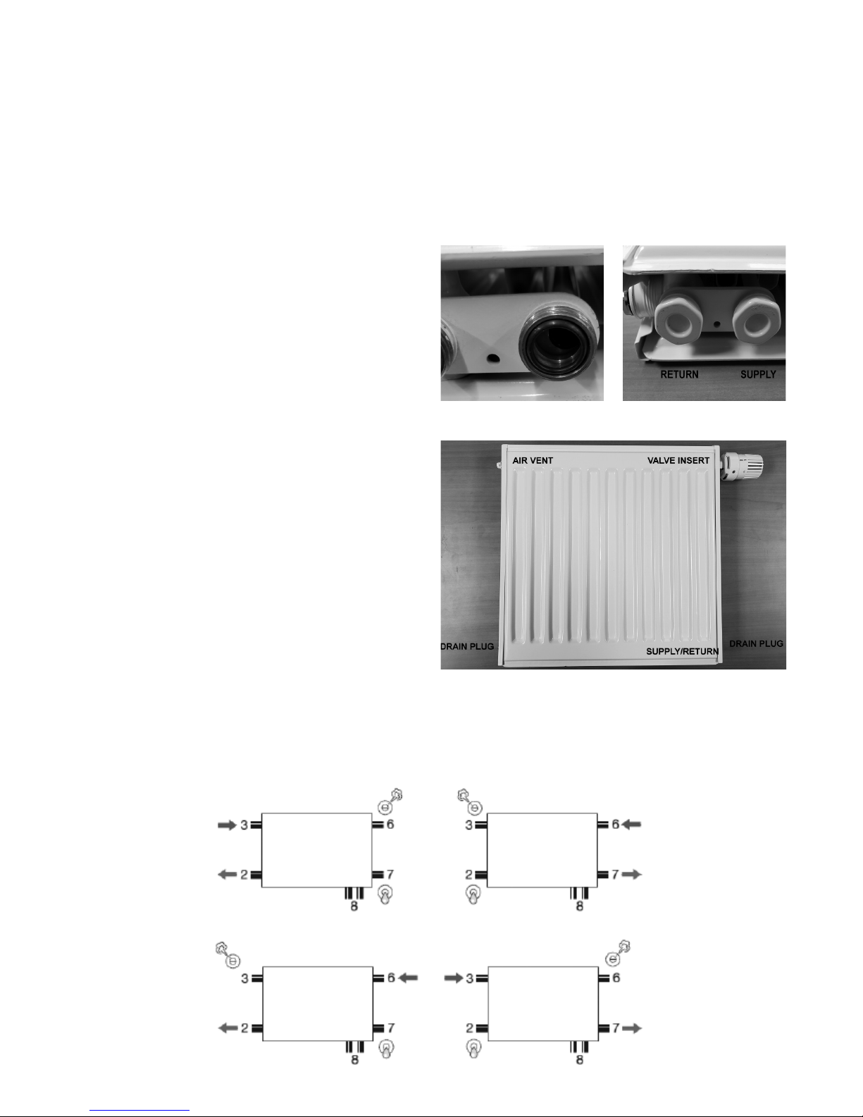
Section 4: Piping
Check that the unit is rmly in place. Piping to the unit
can be done using copper or pex pipe.
Choose a piping arrangement that is suitable for the
job. The unit has 6 possible connection points. Two
on each side and a bottom connection that can be
installed on either the left hand or right hand side as
the units are reversible (for all units except the Type
11). If piping from the bottom, remove the metal covers
and the o-rings (see g 13). Failure to remove the
o-ring will prohibit proper installation of accessories
and may cause leaking.
For a bottom piping arrangement, the supply is to the
inside of the unit, and the return to the outside (see
g 14). Should the unit get installed with the incorrect
piping arrangement, valves (part # 1016362) are
available to reverse the piping with little disruption.
The unit was supplied with 2 blind stops (drain plugs),
an air vent, and a thermostatic valve insert and cover.
For bottom piping arrangements, remove the
temporary plugs from the left and right hand side
lower ports and install the chrome drain plugs. The
thermostatic valve and insert must be installed on
the same side as the supply and return port located
at the bottom of the unit. If piping is on the bottom
left hand side, the thermostatic valve and insert
must be installed on the top left hand port. Failure to
install correctly will result in noise. Once the insert is
installed, a thermostatic head may be installed. If a
thermostatic head will not be installed, cover the insert
with the white plastic cover supplied with unit. The air
vent should be installed on the upper corner opposite
the valve insert. See gure 15 for recommended
placement of accessories for bottom piped units.
Once all the connections have been made, the air must
be purged from the system. This can be accomplished
using the coin air vent that was supplied with the unit.
Figure 13 – O-ring
Figure 15 – Accessory placement
Figure 14 – Supply / Return
connections
Alternative Piping Arrangements
Below are the recommended alternative piping connections when not piping from the bottom. For alternative
piping arrangements not shown, please consult the factory.
7
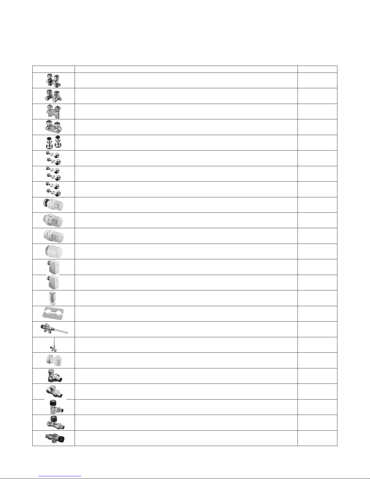
Section 5: Accessories
Below is a listing of accessories available through Beacon Morris. It is recommended that these accessories be
installed with the Beacon Morris Panel Radiator units to insure proper operation.
Description Part Number
Straight H Valve for Isolation and bypass 3/4"F x 3/4"M (connection pieces included)* 551015943
Angled H Valve for Isolation and bypass 3/4"F x 3/4"M (connection pieces included)* 551015944
Straight reverse connection H valve 3/4"F x 3/4"M (connection pieces included)* 551016362
Angled reverse connection H valve 3/4"F x 3/4"M (connection pieces included)* 551016462
Compression tting, set of 2, for 1/2" copper 551016844
Compression tting, set of 2, for 3/8" PEX/PEX-Al-PEX 551646849
Compression tting, set of 2, for 1/2" PEX/PEX-Al-PEX 551646850
Compression tting, set of 2, for 5/8" PEX/PEX-Al-PEX 551646851
"Vindo TH" non-electric thermostat 551013066
"Uni-LH" non-electric thermostat 551011365
"Uni LHB" non-electric thermostat with vandal resistant design 551011410
Manual valve handle 551012565
Electromotive actuator for 2-pt, 3-pt, and 0-10V control 551012705
Electromotive actuator for 0-10V control with position feedback signal 551012706
Electrothermal actuator for 2-pt control, normally closed 551012416
Rosette cover for pipe entry 551016674
Single entry radiator valve with horizontal insertion tube, with bypass 551183561
Single entry radiator valve with vertical insertion tube, with bypass 551183571
Right angle adapter M30 x 1.5 551011450
Angle radiator balancing and shut off valve 1/2" NPT 551091082
Straight radiator balancing and shut off valve 1/2" NPT 551091182
Angle radiator valve 1/2" NPT 551889004
Straight radiator valve 1/2" NPT 551889104
Reverse angle radiator valve 1/2" NPT 551889204
*For H valves purchased through Beacon Morris (part #s 1015943/44 1016362/6462) included in the valve are the connection pieces.
These rings must be installed with the valve to prevent leaking.
260 NORTH ELM STREET, WESTFIELD, MASSACHUSETTS 01085
7555 TRANMERE DRIVE, MISSISSAUGA, ONTARIO L5S 1L4 CANADA
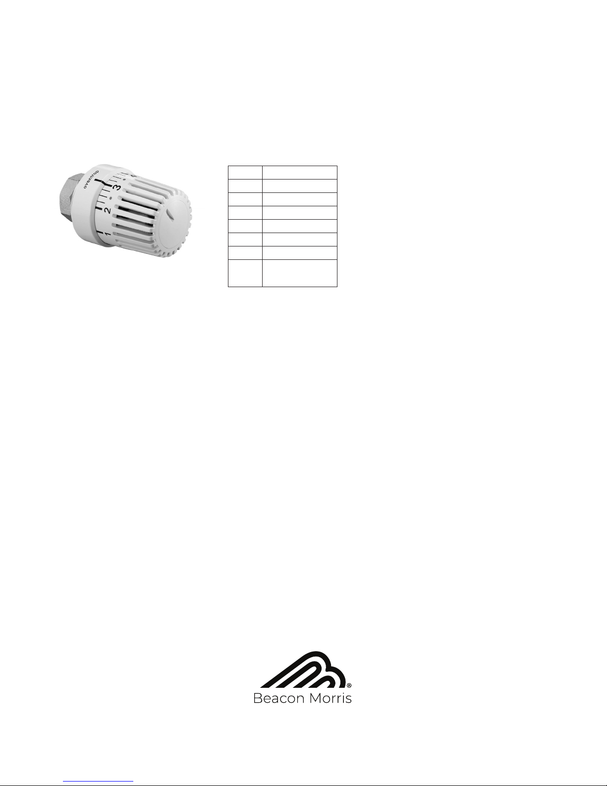
Thermostatic Valve Settings
The thermostats purchased through Beacon Morris have multiple settings. Refer to the chart below for set points
in relation to the number on the valve. The snowake setting is a low ow / non-freeze setting. This will allow a
small amount of water ow to prevent the unit from freezing. If the thermostat is set at 0, no water will ow and
the unit will be off. Refer to gure 16 for the temperature ratings.
Section 8: Cleaning the Unit
The unit may be cleaned using a vacuum or long handled brush.
Never use abrasive cleaners or cleaning products with chemicals as this may compromise the integrity of the
nish. The outside of the units can be cleaned with a non-abrasive cloth or sponge and soap. Thoroughly dry the
unit with a soft cloth.
Code Temperature
0 OFF
1 54°F
2 61°F
3 68°F
4 75°F
5 80°F
Non-freeze/
Low ow
Figure 16 – Tstat Temperature Ratings
"Uni-LH" non-electric thermostat
Part # 1011465 shown
Table of contents


