Beacon 3470 BTR User manual

Model 3470 BTR Beacon Tracking Receiver 1
Model 3470 BTR
Beacon Tracking Receiver
A tracking receiver for antenna step tracking
or automatic uplink power control
1. Functional Description
1.1 The Model 3470 BTR is a fully frequency agile satellite receiver designed
to provide a DC reference voltage proportional to the received signal level of a
satellite beacon or other SCPC carrier. The receiver has a pre-detection
bandwidth of 50 KHz. Frequency selection of the desired carrier is
accomplished from the front panel or by remote serial link. The minimum step
size is 10 kHz. Programming instructions are outlined in the back section of
this manual.
2. Model 3470 BTR Unit Specifications
Input Frequency .................................67.5 to 72.5 MHz
Input Level .........................>-60 dBm, front panel adjustable
Input Impedance .........................................50 ohm
Frequency Selection .............................Local or remote over
+2.5 MHz on 10 KHz steps
Threshold .................................4 dB C/N for acquisition
< 1 dB C/N for carrier lock
Alarms ......................................Local/Alarm Display
Form-C relay contacts
AFC ................................................±25 KHz,
Noise Bandwidth .........................................50 KHz
Output Level .......Internal op amp scalable 0 to 10 VDC, 7.5VDC NOMINAL
Tracking Response ..........................0.5 volts change for 1 dB
change of input level.
MECHANICAL:
Input Connector ............................BNC (Female) 50 Ohm
Output Connector ............................Modular socket & plug
M&C Connector ....................................DB-9, Female
M&C Interface ..................RS-232 or RS-485 (factory configured)
DIMENSIONS: .........................Single 19" rack unit, 16" deep
POWER ..................................110/230 VAC 40-60 Hz
auto-sensing

Installation and Alignment
Model 3470 BTR Beacon Tracking Receiver 2
3. Front Panel Facilities 3.1 DISPLAY
3.1.1 Receive Frequency
The frequency to which the 3470 is tuned is displayed in the upper left
corner of the LCD display.
3.1.2 Carrier Lock or Alarm Status
When the 3470 is locked to a carrier, the LCD will display LOCK in
the upper right corner. When the 3470 is not locked to a carrier, the
LCD will display ALARM.
3.1.3 VDC Output
The tracking reference DC level output from the 3470 will be
displayed in the bottom left corner of the LCD display.
3.1.4 Input Gain
The RF input to the 3470 may be adjusted to the receiver’s linear
range. A number between 400 and 999, which represents the input
attenuation, is displayed in the bottom right corner of the LCD display.
3.2 KEYPAD
3.2.1 The L/R key is used to toggle the Local or Remote mode of operation.
To place the unit in LOCAL or REMOTE mode of operation, hold the L/R
key and simultaneously press and then release the RESET key. After the
display changes, release the L/R key. The unit will change modes of operation
and retain the new mode selected.
3.2.2 The RIGHT ARROW key moves the cursor on the LCD display.
NOTE: Hold the CUR key to enable the RIGHT ARROW key. Use the
RIGHT ARROW key to position the cursor under the LCD digit you wish to
change. The number above the cursor is the number which will change when
the +or -key is pressed. When you release the CUR key, the frequency is
updated internally. If an invalid frequency is selected, the colon [:] after FREQ
will blink.

Installation and Alignment
Model 3470 BTR Beacon Tracking Receiver 3
3.2.3 The +key is used alone to increase gain. The +key is also used in
conjunction with the CUR key to change frequency. The +key increases the
RF input gain by reducing an attenuator inside the 3470. A number between G:
400 and G: 999, which represents the input attenuation, is displayed in the
bottom right corner of the LCD display.
3.2.4 The -key is used alone to decrease gain. The -key is also used in
conjunction with the CUR key to change frequency. The - key decreases the
RF input gain by reducing an attenuator inside the 3470. A number between G:
400 and G: 999, which represents the input attenuation, is displayed in the
bottom right corner of the LCD display.
3.2.5 The RESET key is used to toggle the Local or Remote mode of
operation. To place the unit in LOCAL or REMOTE mode of operation, hold
the L/R key and simultaneously press and then release the RESET key. After
the display changes, release the L/R key. The unit will change modes of
operation and retain the new mode selected.
4. Rear Panel Facilities
4.1 Rear Mounted Terminal Plug (provided)
8 - SS Provides a DC reference proportional to the received
signal input level. This DC level changes
approximately 0.5 volts for a one dB input signal
level change over a 0 to 10.0 VDC range. Normal;
+7.5 VDC for -70 dBm input.
7 - GND Signal Ground
6 - PWR-1 Not Used
5 - PWR-2 Not Used
4 - N/A Not Used
3 - COM Alarm relay common
2 - N/O Normally open relay contact. Open with respect to
common when unit is LOCKED to beacon.
1 - N/C Normally closed relay contact. Closed with respect to
common when unit is LOCKED to beacon.
4.2 IF Input
4.2.1 BNC Female connector for input of 67.6MHz to 72.5MHz.

Installation and Alignment
Model 3470 BTR Beacon Tracking Receiver 4
The serial protocol of the 3470 is fixed at 1200N81. 1200 baud, no parity, eight bits, 1 stop bit.
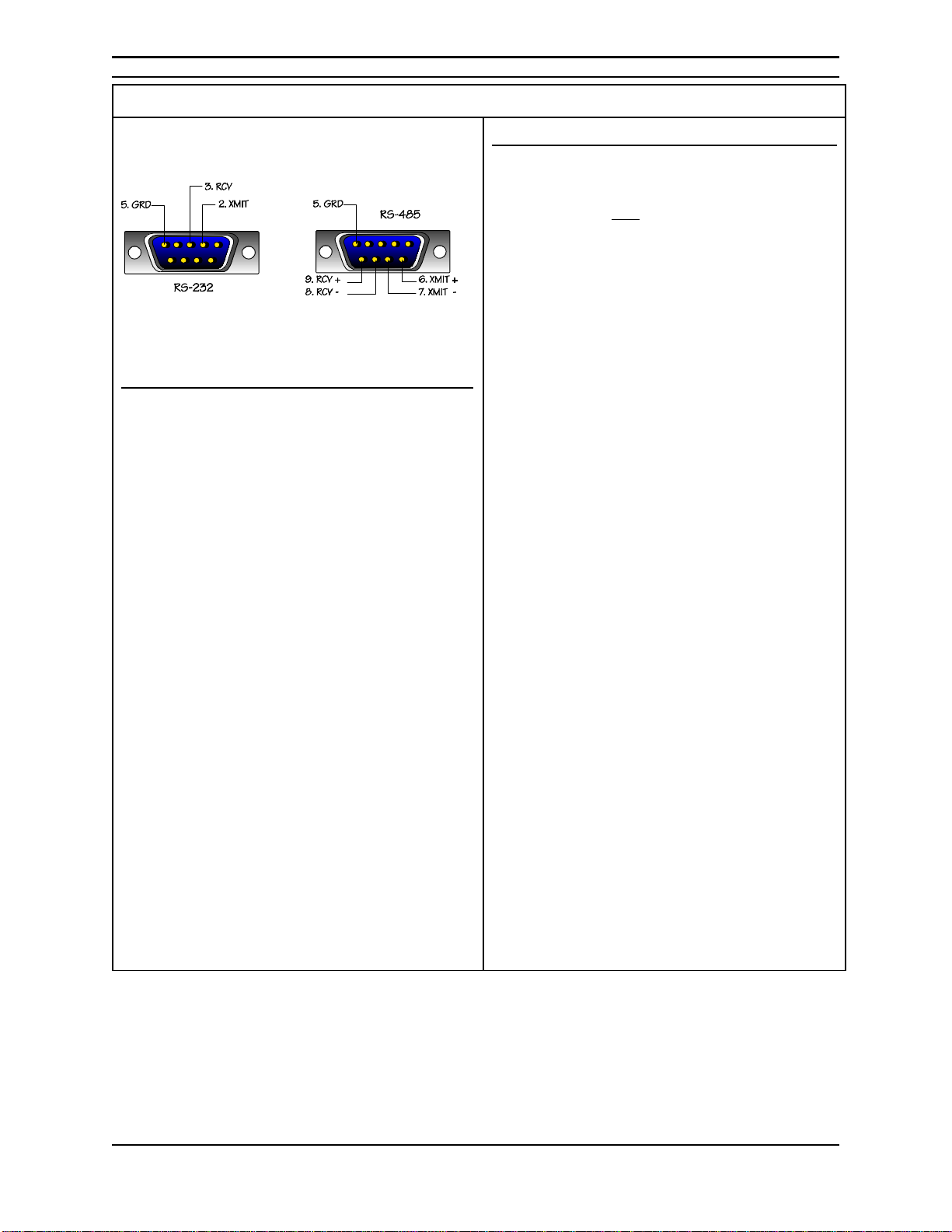
RS-232
Polling the 3470
?To query a status report from the 3470, send
the command string: (F, space) That is, the
ascii letter “F” followed by a space
?The unit will respond with:
FREQ=(receive frequency), GAIN=(gain),
SS=(signal strength voltage), L (lock) or A
(alarm)
Changing the frequency and gain
?Send the command string:
(F space frequency in MHz, space, frequency
in KHz, space,gain, space)
WHERE:
?frequency in MHz =67.5 - 72.5 Mhz
in 1 MHz increments
?frequency in KHz = 00 to 99 in 10
KHz increments
?gain = a relative number between 400
and 999.
?The entire command string must be
transmitted in all cases; to change frequency,
gain or both.
?If an incomplete command string is sent, the
unit will respond with the current conditions
as if being polled.
?If an incorrect command string is sent, the
unit will not respond
RS-485
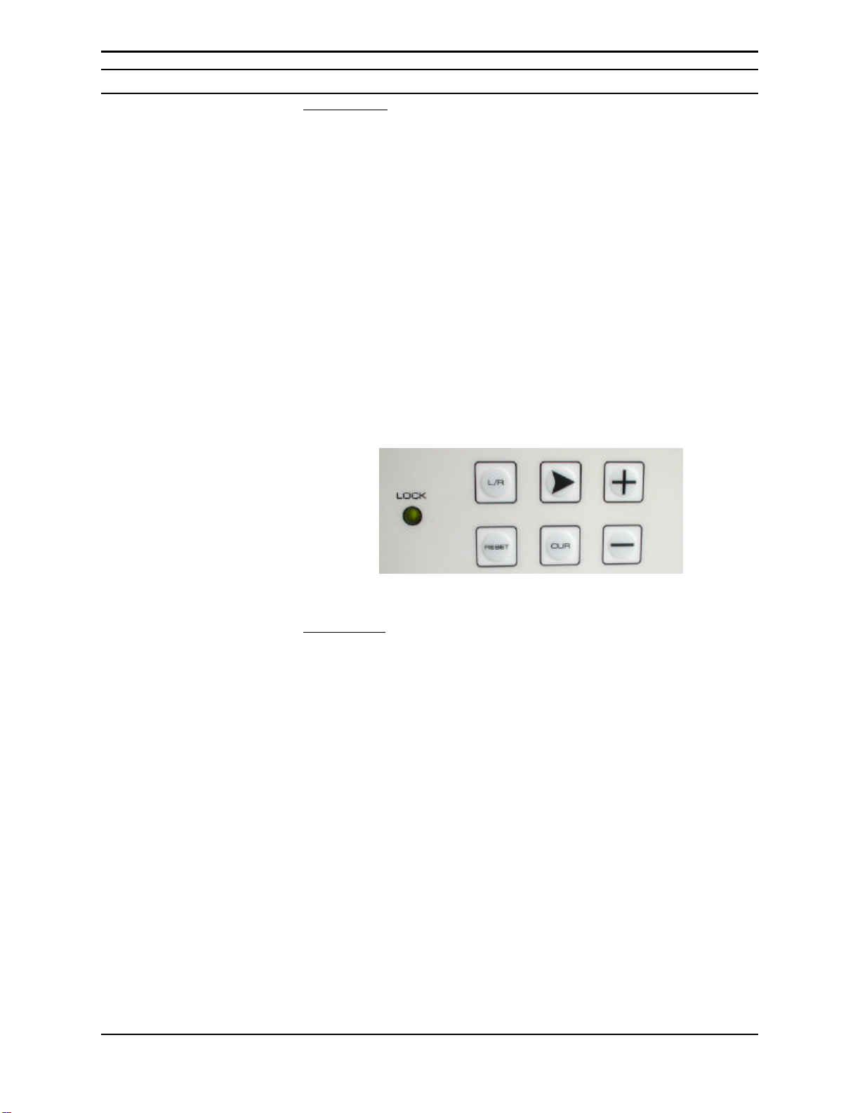
Changing the RS 485 serial address
?The unit must be in remote mode to change
the serial address.
?Press and hold the CUR key.
?Press and release the RESET key (continue
to hold the CUR key).
?Continue to press and hold the CUR key;
press and release the L/R key. As the L/R
key is pressed and released, the address will
scroll up in value.
?When you have reached the address value
you want, release the CUR key.
?The address range is from the
number 1 through the letter F.
Polling the 3470
?To query a status report from the 3470, send
the command string: (hex address, space)
That is, the address value you have assigned
followed by a space in hexadecimal.
?The unit will respond with:
ADD= (hex address), FREQ=(receive
frequency), GAIN=(gain), SS=(signal
strength voltage), L (lock) or A (alarm)
Changing the frequency and gain
?Send the command string:
(hex address, space, frequency, space,gain,
space) WHERE:
?hex address = 1 through F
?frequency = 67.50 to 72.50 Mhz
?gain = a relative number between
400 and 999.
?The entire command string must be
transmitted in all cases; to change frequency,
gain or both.
?If an incomplete command string with the
correct address is sent, the unit will respond
with the current conditions as if being polled.
?If an incorrect command string with the
correct address is sent, the unit will not
respond
?If the correct address is not transmitted the
unit will not respond.

Installation and Alignment
Model 3470 BTR Beacon Tracking Receiver 5
5. SYSTEM ALIGNMENT PROCEDURE
5.1 Install a 50 ohm, BNC cable between the downconverter and the MODEL
3470 BTR .
5.2 Plug the AC cord which is provided with the unit into the rear mounted
receptacle. Plug the male end of the power cord into a suitable 90-260 VAC,
47-60 HZ power outlet. The MODEL 3470 BTR 's power supply
automatically detects AC input voltage.
5.3 Tune the 3470 to the beacon frequency.
5.4 Adjust the 3470 gain to 999. (Refer to paragraph 3.2.3 or 5.2)
5.5 If the antenna system is properly aligned to the appropriate satellite and
polarity the LCD display will show LOCK in the upper right corner. Observe
the GAIN value at the lower right corner of the LCD display. Adjust the gain
(refer to paragraph 3.2.3 or 5.2) for a DC level as nearly as possible to + 7.5
Volts. This sets the input gain for the receiver’s most linear range.
5.6 The antenna can be optimally aligned while monitoring this voltage for a
maximum reading. If necessary readjust the GAIN to achieve + 7.5 VDC.
Work Sheet
Model 3470 BTR
SERIAL NUMBER _____________ Date ________________
Input Signal
Level dBm Output
VDC Input Signal
Level dBm Output
VDC
-35 dBm -46 dBm
-36 dBm -47 dBm
-37 dBm -48 dBm
-38 dBm -49 dBm
-39 dBm -50 dBm
-40 dBm -51 dBm
-41 dBm -52 dBm
-42 dBm -53 dBm
-43 dBm -54 dBm
-44 dBm -55 dBm
-45 dBm

Installation and Alignment
Model 3470 BTR Beacon Tracking Receiver 6

Troubleshooting Guide
Model 3470 BTR Beacon Tracking Receiver 7
Symptom
1. No power to unit.
Cause
1. AC power fuse blown.
Note: the AC power fuse is located inthe rear mounted
power connector. A spare fuse is also located within.
2. Insure there is proper AC power to the unit. The
unit can operate on either 220VAC or 120VAC with
the use of the associated power cord.
2.Alarm Condition 1. Unit not tuned to proper receive frequency. Recheck
tuning table and procedure.
2. The Carrier-to-Noise (C/N) of the receive signal is
not adequate for unit to operate.
Note: the C/N is afunction of the downlink power of
the carrier as well as the G/T (figure-of-merit) of the
receive system.
3. The carrier level is too low.
Adjust the downconverter output to insure >-60 dBm
input to the 3470 BTR.
3. Lock but low DC output tracking voltage. 1. Signal level too low to unit (see above).
2. Low C/N. Unit may be noise driven which
minimizes signal level sensitivity.
4. Lockbut high outputtracking voltage with
no change when input signal level changes. 1. I.F. input level adjust set too high. Unit is in
compression. Refer to alignment procedure.
NOTE: When in compression [too much input level]
the DC signal strength may increase as the input level
decreased when the unit is going out of compression.
Continue todecreaseinputleveluntil alinear response
is obtained, ie; 7.5 volts.
Note: there are no internal adjustments within the receiver. If it is determined that the unit has
failed, refer to the Satellite Systems Corporation Repair Return Policy which follows.

Repair and Warranty Policies
Model 3470 BTR Beacon Tracking Receiver 8
Repair Service Policy
In the event of an equipment failure, the defective unit should be replaced with aspare unit and then returned to the
factory for correction. Returned units are normally repaired and returned within 10 working days from receipt of unit.
In many cases, Satellite Systems Corporation, can supply the customer with a field loan unit during the repair of his
equipment. Loan equipment is subject to availability at the time of request. The standard loan charge, equal to the
current minimum shop rate, plus freight will be charged in the form of a C.O.D. shipment for each unit loaned
regardless of the warranty status and any subsequent charges for the repair of the equipment to be repaired.
In the interest of minimizing repair processing time, Satellite Systems Corporation requires notification prior to the
return of the defective equipment. Upon notification, Satellite Systems Corporation will assign an RMA (Returned
Material Authorization) number that should appear on the outside of the package containing the defective equipment.
Other information should accompany equipment being returned are Purchase Order Number, shipping and billing
address(es), contact name, telephone number and a comprehensive description of the failure.
For equipment returned that Satellite Systems Corporation finds no failure or defect, the current minimum one hour
shop rate will be charged.
Notification may be made by telephone or fax to:
SATELLITE SYSTEMS CORPORATION
Communications Products Division
101 Malibu Dr.
Virginia Beach, VA 23452
Phone Number: (757) 463-3553 Fax Number: (757) 463-3891
Warranty Information
Satellite Systems Corporation (SSC) warrants new equipment to be free from defects in material or workmanship for
a period of 12 months from date of original shipment. This warranty is extended to the original purchaser only and
is not transferable to subsequent owners. If at any time the equipment malfunctions as a result of faulty material or
workmanship,SSCwillrepairthedefect(s)orreplacethe equipment at its sole option. Any such repair or replacement
of said equipment as well as return freight (2 day standard air) shall be made free of charge to the customer through
the warranty period. All repairs shall be made at SSC's facility with all transportation and any other subsequent
charges prior to the receipt of said equipment at SSC's facility shall be the sole responsibility of the customer.
SSC's liability shall not extend beyond the reasonable repair or replacement for the repairs previously described. SSC
does not warrant the equipment to operate in conditions other than those stated within this User Instruction Manual.
SSC makes no other express warranty of any kind whatsoever. All implied warranties, including warranties of
merchantability andfitnessforaparticular purpose, exceeding the duration of this warranty are hereby disclaimed and
excluded from this warranty. SSC disclaims liability for any incidental or consequential damages.
NOTE: Field alignment or repairs other than those provided for within this user instruction manual may void the
equipment warranty and should be authorized by a factory representative prior to implementation.

Model 3470 BTR Beacon Tracking Receiver 9
Regulatory Information
EC Declaration of Conformity
According to ISO/IEC Guide 22 and EN45014:
Manufacturer’s Name: Satellite Systems Corporation
Manufacturer’s Address: 101 Malibu Drive
Virginia Beach, Virginia 23452 U.S.A.
Delares that the product:
Product Name: 3430BTR Beacon Receiver
Model Number(s): 3430 (Product number may be followed by suffixes.)
Conforms to the following Product Specifications:
Safety: IEC 950:1991 +A1 +A2 +A3 / EN60950: 1992 +A1 +A2 +A3
EMC: CISPR 22: 1993, Class B / EN55022: 1994, Class B
IEC 1000-3-2: 1995 / EN61000-3-2: 1995
IEC 1000-3-3: 1995 / EN61000-3-3: 1995
EN50082-1: 1992
IEC 801-2: 1991 / prEN 55024-2: 1992, 4 kV CD, 8 kV AD
IEC 801-3: 1984 / prEN 55024-3: 1991, 3 V/m
IEC 801-4: 1988 / prEN 55024-4: 1992, 1 kV Power Lines
Supplementary Information:
The product herewith complies with the requirements of the Low Voltage Directive 73/23/EEC and
the EMC Directive 89/336/EEC and carries the CE-marking accordingly.
Date: Virginia Beach, Virginia, U.S.A.
June 15, 1997
In order to meet the EMC Directive (EN55022, EN50082-1), properly shielded cable for Serial Data
I/O is required. These cables must be double-shielded from end-to-end, ensuring a continuous
ground shield.
<HAR> Type of power cord required for use in the European
Community
CAUTION: Double-pole/Neutral Fusing
ACHTUNG: Zweipolige bzw. Neutralleiter-Sicherung

Model 3470 BTR
Beacon Tracking Receiver
Instruction Manual
Table of contents