BeaconMedaes VerusLab 4107 9021 88 Manual

Installation, Operation and Maintenance Instructions
VerusLabTM Lubricated Rotary Vane Laboratory
Vacuum System
Part number 4107 9021 88
Revision 01
March 04, 2019


Installation, Operation and Maintenance Manual
VerusLabTM Lubricated Rotary Vane
Laboratory Vacuum System
Part number 4107 9021 88.01
8 February 2019
This unit is purchased from:
Date purchased:
Model number:
Serial number:
Option(s) included:
Any information, service or spare parts requests should include the machine serial number and be
directed to:
BeaconMedæs
1059 Paragon Way,
Rock Hill, SC 29730
Phone: (803) 817-5600
Fax: (803) 817-5750
www.beaconmedaes.com
BeaconMedæs reserves the right to make changes and improvements to update products sold
previously without notice or obligation.

1.0 Introduction .............................................................. 1-1
1.1 Audience ..............................................................................................1-1
1.2 Abbreviations ......................................................................................1-1
1.3 Definition of Statements....................................................................1-1
1.4 Environmental Declarations..............................................................1-1
1.5 Electromagnetic Immunity ...............................................................1-2
2.0 Installation ................................................................ 2-1
2.1 Inspection Upon Receiving ...............................................................2-1
2.2 Handling ..............................................................................................2-1
2.3 Location ..............................................................................................2-1
2.4 Locations Above Sea Level.................................................................2-2
2.5 Electrical Requirements ....................................................................2-2
2.6 Intake Piping........................................................................................2-3
2.7 Electrically Controlled Intake Valve Actuator...................................2-4
2.8 Exhaust Piping.....................................................................................2-4
3A.0 Start Up-TotalAlert Embedded Controls (TAe) ....3A-1
3A.1 Prestart-up.........................................................................................3A-1
3A.2 Initial Start-up....................................................................................3A-2
3A.2.1 Lubrication........................................................................... 3A-2
3A.2.2 Pump Rotation .................................................................... 3A-2
3A.2.3 Direct On Line or Wye Delta Starting................................ 3A-3
3A.3 Initial Operation ................................................................................3A-4
3A.3.1 Testing the Pumps .............................................................. 3A-4
3A.3.2 Automatic Purge Operation............................................... 3A-4
3B.0 Start Up-Basic Controls (PLC) ................................ 3B-1
3B.1 Prestart-up........................................................................................ 3B-1
3B.2 Initial Start-up................................................................................... 3B-2
3B.2.1 Lubrication........................................................................... 3B-2
3B.2.2 Pump Rotation .................................................................... 3B-2
Table of Contents
Lubricated Rotary Vane Laboratory Vacuum Systems
4107 9021 88.01 i

3B.3 Initial Operation............................................................................... 3B-3
3B.3.1 Testing the Pumps.............................................................. 3B-3
3B.3.2 Automatic Purge Operation...............................................3B-3
4A.0 General Operation - TAe ........................................ 4A-1
4A.1 Vacuum Control System.................................................................. 4A-1
4A.1.1 System Description............................................................. 4A-1
4A.1.2 System Operation ............................................................... 4A-1
4A.2 Automatic Purge .............................................................................. 4A-2
4A.3 Tank Drains....................................................................................... 4A-2
4A.4 Emergency Shutdown/Alarms ....................................................... 4A-3
4A.4.1 Pump / System Shutdown ................................................. 4A-3
4A.4.2 Unit Shutdown / Alarms..................................................... 4A-3
4A.4.3 System Alarms..................................................................... 4A-4
4A.4.4 Service Warnings................................................................. 4A-4
4A.4.5 Next In Line Alternation (outside normal function)........ 4A-4
4A.5 Backup Vacuum Switch Set Point Adjustments ........................... 4A-5
4B.0 General Operation - PLC ........................................ 4B-1
4B.1 Vacuum Control System.................................................................. 4B-1
4B.1.1 System Description............................................................. 4B-1
4B.1.2 System Operation ............................................................... 4B-1
4B.2 Automatic Purge .............................................................................. 4B-3
4B.3 Tank Drains....................................................................................... 4B-3
4B.4 Emergency Shutdown/Alarms ....................................................... 4B-3
4B.4.1 Pump / System Shutdown ................................................. 4B-3
4B.4.2 Unit and System Shutdown / Alarms................................4B-4
4B.5 Backup Vacuum Switch Set Point Adjustments ........................... 4B-4
5.0 Troubleshooting........................................................ 5-1
6.0 Maintenance ............................................................. 6-1
6.1 General Maintenance.........................................................................6-1
Table of Contents (continued)
Lubricated Rotary Vane Laboratory Vacuum Systems
4107 9021 88.01ii

6.1.1 Vacuum Pump ........................................................................6-2
6.2 Lubrication...........................................................................................6-2
6.2.1 Oil Type ...................................................................................6-2
6.2.2 Oil Level...................................................................................6-3
6.2.3 Automotive-Type Oil Filter ....................................................6-3
6.2.4 Greasing the Motor Bearings ...............................................6-4
6.3 Drip Leg and Filters.............................................................................6-4
6.3.1 Exhaust Drip Leg Valve..........................................................6-4
6.3.2 Inlet Filter ................................................................................6-4
6.3.3 Exhaust Filter..........................................................................6-4
6.4 Receiver Tank Drain............................................................................6-6
6.5 General Inspections............................................................................6-6
6.5.1 Monthly Inspections ..............................................................6-6
6.5.2 Every Six Months....................................................................6-6
6.5.3 Oil Leak....................................................................................6-6
7.0 Replacement / Maintenance Parts ......................... 7-1
8.0 Maintenance Record ................................................ 8-1
Appendix A TotalAlert Embedded (TAe)........................ A-1
A.1 Board Configurations........................................................................ A-2
A.2 PCB1 (5.7” Display Controller) .......................................................... A-2
A.2.1 Basic Software Architecture ................................................ A-2
A.2.2 5.7” User Interface for Source Systems.............................. A-2
A.2.3 5.7” Boot/Communication Screen ...................................... A-3
A.2.4 5.7” Main Screen ................................................................... A-3
A.2.5 5.7” Trend Screen.................................................................. A-4
A.2.6 5.7” Service Screen................................................................ A-4
A.2.7 5.7” Maintenance Screen ..................................................... A-5
A.2.8 5.7” Alarms Screen................................................................ A-6
A.2.9 5.7” Shutdown Screen .......................................................... A-6
Table of Contents (continued)
Lubricated Rotary Vane Laboratory Vacuum Systems
4107 9021 88.01 iii

A.2.10 5.7” History Screen ............................................................... A-6
A.2.11 5.7” Settings Screen .............................................................. A-7
A.2.12 5.7” Lab Vacuum Settings Screen........................................ A-8
A.3 PCB2 (3.5” Display Controller) .......................................................... A-8
A.3.1 Basic Software Architecture ................................................ A-8
A.3.2 3.5” User Interface for Source Systems.............................. A-8
A.3.3 3.5” Boot/Communication Screen ...................................... A-9
A.3.4 3.5” Main Screen ................................................................... A-9
A.3.5 3.5” Main Screen: Manual Override.................................... A-9
A.3.6 3.5” Status Screen ............................................................... A-10
A.3.7 3.5” Service Screen.............................................................. A-10
A.3.8 3.5” Alarms Screen.............................................................. A-11
A.3.9 3.5” Shutdown Screen ........................................................ A-11
A.4 Password Access.............................................................................. A-11
A.4.1 Main Screen Password Items ............................................ A-12
A.4.2 Unit Screen Password Items.............................................. A-12
A.5 Testing Alarms.................................................................................. A-12
A.6 Maintenance..................................................................................... A-12
A.6.1 Maintenance Screens ......................................................... A-12
A.6.2 Maintenance Alerts............................................................. A-13
A.6.3 Resetting a Service Activity ................................................ A-13
A.7 Remote Monitoring ......................................................................... A-13
A.7.1 Set Up: Equipment Required............................................. A-14
A.7.2 Set Up: Physical Connection .............................................. A-14
A.7.3 Set Up: Network Connection ............................................. A-14
A.7.4 Set Up: Connecting to the Embedded Website of the
Vacuum System................................................................... A-14
A.7.5 Login to Setup Pages .......................................................... A-15
A.7.6 Device Setup........................................................................ A-15
Table of Contents (continued)
Lubricated Rotary Vane Laboratory Vacuum Systems
4107 9021 88.01iv

A.7.7 Network Setup .................................................................... A-16
A.7.8 Website Setup ..................................................................... A-16
A.7.9 System Trend Setup ........................................................... A-16
A.7.10 Electronic Notification Setup ............................................. A-17
A.7.11 Navigating the Website ...................................................... A-17
A.7.12 Available for Download...................................................... A-20
Table of Contents (continued)
Lubricated Rotary Vane Laboratory Vacuum Systems
4107 9021 88.01 v

Safety Precautions
The operator should carefully read the entire
contents of this manual before installing, wiring,
starting, operating, adjusting and maintaining
the system.
The operator is expected to use common-sense
safety precautions, good workmanship practices
and follow any related local safety precautions.
In addition:
• Before starting any installation or
maintenance procedures, disconnect all
power to the package.
• All electrical procedures must be in
compliance with all national, state, and local
codes and requirements.
• A certified electrician should connect all
wiring.
• Refer to the electrical wiring diagram
provided with the unit before starting any
installation or maintenance work.
• Release all vacuum from the affected
components before removing, loosening,
or servicing any covers, guards, fittings,
connections, or other devices.
• Notify appropriate facility personnel if
repairs or maintenance will affect available
vacuum levels.
• This is a high speed, rotating piece of
machinery. Do not attempt to service any
part while machine is in operation.
• To prevent automatic starting, disconnect
all electrical power before performing any
maintenance functions.
• Do not operate unit without guards, shields
or screens in place.
• Make sure that all loose articles, packing
material, and tools are clear of the package.
• Check all safety devices periodically for
proper operation.
• Electrical service must be the same as
specified on the control panel nameplate or
damage to the equipment may occur.
• Vibration during shipment can loosen
electrical terminals, fuse inserts, and
mechanical connections. Tighten all electrical
connections prior to energizing the control
panel
Lubricated Rotary Vane Laboratory Vacuum Systems
4107 9021 88.01vi

1.1 Audience
This manual provides information related to
the installation and operation of the VerusLab
Lubricated Rotary Vane Laboratory Vacuum
System manufactured by BeaconMedæs. Service
information contained in this manual is intended
for use by technicians or personnel qualified to
repair and service laboratory equipment.
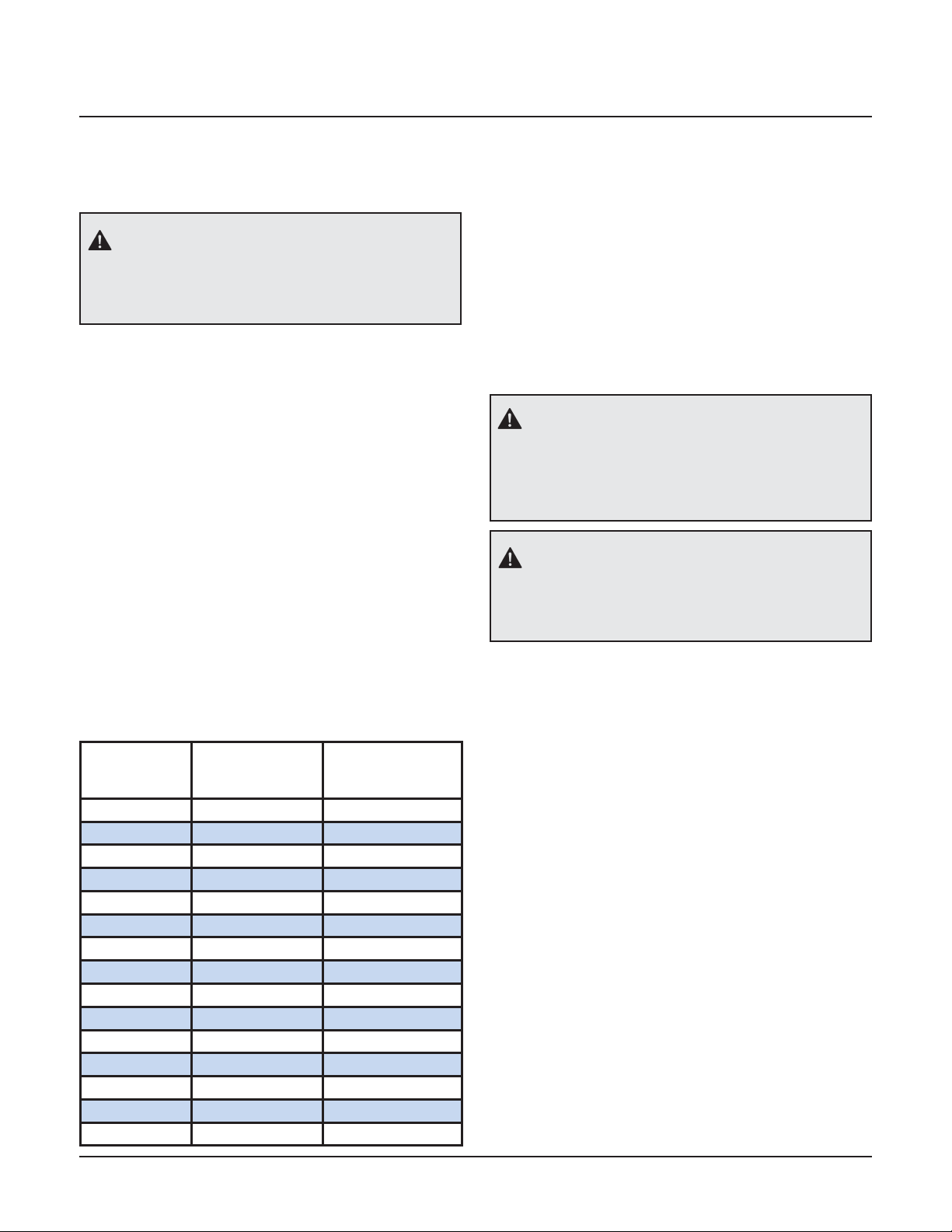
1.2 Abbreviations
C Common
CGA Compressed Gas Association
FNPT Female National Pipe Thread
MNPT Male National Pipe Thread
N/C Normally Closed
N/O Normally Open
PSIG Pounds Per Square Inch- Gauge
SCFM Standard Cubic Feet Per Minute
VAC Voltage, Alternating Current
VDC Voltage, Direct Current
1.3 Definition of Statements
Statements in this manual preceded by
following words are of special significance.
WARNING: Means there is a possibility of
injury or death to yourself or others.
CAUTION: Means there is a possibility of
damage to unit or other property.
NOTE: Indicates points of particular interest for
more efficient and convenient operation.
1.4 Environmental Declarations
General
When developing products and services,
BeaconMedæs tries to understand, address, and
minimize the negative environmental effects
that the products and services may have, when
being manufactured, distributed, and used, as
well as at their disposal.
Recycling and disposal policies are part of the
development of all BeaconMedæs products.
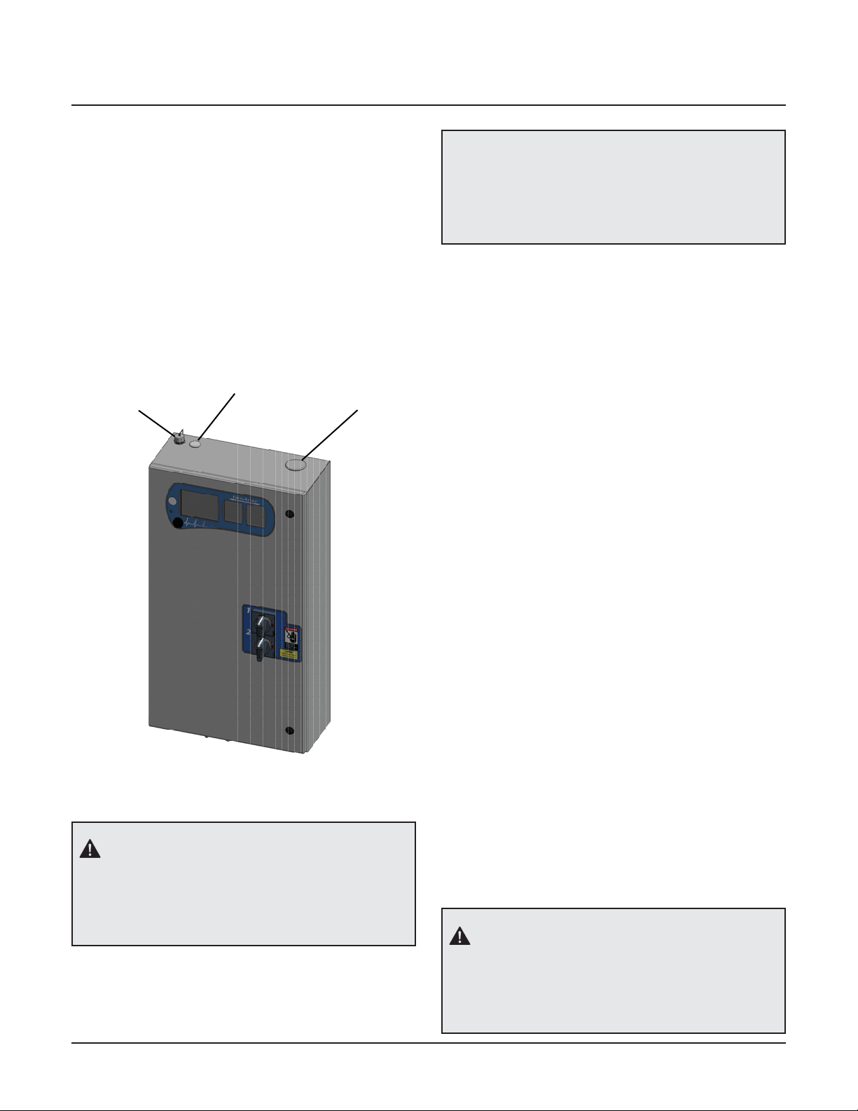
WARNING:
The vacuum pump may be contaminated with
dangerous foreign materials. Use personal
protective equipment (protective gloves,
protective eyewear, protective respiratory
equipment) during dismantling of the pump.
BeaconMedæs company standards determine
strict requirements.
When selecting materials, the substantial
recyclability, the disassembly possibilities and
the separability of the materials and assemblies
are considered as well as the environmental
perils and dangers to health during the recycling
and disposal of the unavoidable rates of non-
recyclable materials.
BeaconMedæs products for the most part
consist of metallic materials that can be
remelted in steelworks and smelting works and
that is therefore almost infinitely recyclable. The
plastic use is labeled; sorting and fractioning
of the materials for recycling in the future is
foreseen.
Disposal of Materials
Dispose contaminated substances and materials
separately, according to local applicable
environmental legislations.
Dispose all components according to the
applicable disposal regulations.
NOTE:
This concept can only succeed with
your help. Support us by disposing
professionally.
By assuring a correct disposal of the
product you help to prevent possible
negative consequences for environment
and health that can occur with
inappropriate waste handling.
Recycling and re-usage of materials helps
to preserve natural resources.
1.0 Introduction
Lubricated Rotary Vane Laboratory Vacuum Systems
4107 9021 88.01 1-1

1.5 Electromagnetic Immunity
EN 61000-6-2
Electrical Equipment needs special precautions
regarding EMC and needs to be installed and put
into service according to the EMC information
provided in this manual.
Portable and mobile RF communications
equipment can affect Medical or other Electrical
Equipment.
Guidance and manufacturer’s declaration - electromagnetic immunity
The TotalAlert Embedded control system is intended for use in the electromagnetic environment specified below. The
customer or the user of the TotalAlert Embedded control system should assure that it is used in such an environment.
Immunity test IEC 60601
test level Compliance level Electromagnetic environment - guidance
Electrostatic
Discharge (ESD)
IEC 61000-4-2
±6 kV contact
±8 kV air
±6 kV contact
±8 kV air
Floors should be wood, concrete, metal or
ceramic tile. If floors are covered with synthetic
material, the relative humidity should be at least
30 %.
Electrical fast
transient/burst
IEC 61000-4-4
±2 kV for power
supply lines
±1 kV for input/
output lines
±2 kV for power supply
lines
±1 kV for input/output
lines
Mains power quality should be that of a typical
commercial or hospital environment.
Surge
IEC 61000-4-5
±1 kV differential
mode
±2 kV common mode
±1 kV differential mode
±2 kV common mode
Mains power quality should be that of a typical
commercial or hospital environment
Voltage dips, short
Interruptions and
voltage variations
on power supply
input lines
IEC 61000-4-11
<5 % UT
(>95 % dip in UT)
for 0,5 cycle
<40 % UT
(>60 % dip in UT)
for 5 cycles
<70 % UT
(>30 % dip in UT)
for 25 cycles
<5 % UT
(>95 % dip in UT)
for 5 sec
<5 % UT
(>95 % dip in UT)
for 0,5 cycle
<40 % UT
(>60 % dip in UT)
for 5 cycles
<70 % UT
(>30 % dip in UT)
for 25 cycles
<5 % UT
(>95 % dip in UT)
for 5 sec
Mains power quality should be that of a typi-
cal commercial or hospital environment. If the
user of the TotalAlert Embedded control system
requires continued operation during power mains
interruptions, it is recommended that the system
be installed on an emergency power service.
Power frequency
(50/60 Hz) magnetic
field
IEC 61000-4-8
3 A/m 3 A/m Power frequency magnetic fields should be at lev-
els characteristic of a typical location in a typical
commercial or hospital environment.
NOTE: UTis the a.c. mains voltage prior to application of the test level.
The use of accessories, transducers, and cables
other than those specified by the manufacturer,
may result in decreased immunity of the
TotalAlert Embedded control system.
The TotalAlert Embedded control system should
not be used adjacent to other equipment.
If adjacent use is necessary, the TotalAlert
Embedded control system should be observed
to verify normal operation in the configuration
in which it will be used.
Lubricated Rotary Vane Laboratory Vacuum Systems
4107 9021 88.011-2

1.5 Electromagnetic Immunity (cont.)
Guidance and manufacturer’s declaration - electromagnetic immunity
The TotalAlert Embedded control system is intended for use in the electromagnetic environment specified below. The
customer or the user of the TotalAlert Embedded control system should assure that it is used in such an environment.
Immunity test IEC 60601
test level Compliance level Electromagnetic environment - guidance
Conducted RF
IEC 61000-4-6
Radiated RF
IEC 61000-4-3
3 Vrms
150 kHz to 80 MHz
3 V/m
80 MHz to 2,5 GHz
3 Vrms
3 V/m
Portable and mobile RF communications equip-
ment should be used no closer to any part of the
TotalAlert Embedded control system, including ca-
bles, than the recommended separation distance
calculated from the equation applicable to the
frequency of the transmitter.
Recommended separation distance
d = 1,2√P
d = 1,2√P 80 MHz to 800 MHz
d = 2,3√P 800 MHz to 2,5 GHz
where P is the maximum output power rating
of the transmitter in watts (W) according to the
transmitter manufacturer and d is the recom-
mended separation distance in metres (m).
Field strengths from fixed RF transmitters, as
determined by an electromagnetic site survey,a
should be less than the compliance level in each
frequency range.b
Interference may occur in the vicinity of equip-
ment marked with the following symbol:
NOTE 1 At 80 MHz and 800 MHz, the higher frequency range applies.
NOTE 2 These guidelines may not apply in all situations. Electromagnetic propagation is affected by absorption and
reflection from structures, objects and people.
Field strengths from fixed transmitters, such as base stations for radio (cellular/cordless) telephones and land
mobile radios, amateur radio, AM and FM radio broadcast and TV broadcast cannot be predicted theoretically with
accuracy. To assess the electromagnetic environment due to fixed RF transmitters, an electromagnetic site survey
should be considered. If the measured field strength in the location in which the TotalAlert Embedded control
system is used exceeds the applicable RF compliance level above, the TotalAlert Embedded control system should
be observed to verify normal operation. If abnormal performance is observed, additional measures may be neces-
sary, such as reorienting or relocating the TotalAlert Embedded control system.
Over the frequency range 150 kHz to 80 MHz, field strengths should be less than 3 V/m.
a
b
Lubricated Rotary Vane Laboratory Vacuum Systems
4107 9021 88.01 1-3

2.1 Inspection Upon Receiving
The condition of the VerusLabTM Lubricated
Rotary Vane Laboratory Vacuum System should
be carefully inspected upon delivery. Any
indication of damage by the carrier should be
noted on the delivery receipt, especially if the
system will not be immediately uncrated and
installed. BeaconMedæs ships all systems F.O.B.
factory; therefore, damage is the responsibility
of the carrier, and all claims must be made with
them. Lube systems may remain in their shipping
containers until ready for installation. If Lube
systems are to be stored prior to installation,
they must be protected from the elements to
prevent rust and deterioration. Lube systems
in storage must be rotated over by hand every
three months.
The shelf life of inlet filters is one year. Systems
stored longer than one year should have all
filters replaced prior to first start-up. See Section
7.0 for replacement filter kits.
DO NOT REMOVE the protective covers from
the inlet and discharge connection ports of the
unit until they are ready for connection to your
system.
2.2 Handling
The vacuum package can be moved with either a
forklift or dollies. Keep all packing in place during
installation to minimize damage. Walk along the
route the unit must travel and note dimensions
of doorways and low ceilings.
Most single point connection systems can be
separated for installation purposes. If separating
bases, carefully label all removed electrical
connections for easier re-assembly at the final
destination.
Tipping the pump over can cause oil to flood the
cylinder. Whenever the pump is transported, be
sure to drain the oil prior to shipping to avoid
vane breakage when restarting the pump.
Refer to the diagrams supplied with your
system for dimensional, wiring and installation
information.
Place units to ensure high visibility of indicators
and gauges and for performing maintenance
on the system. Refer to your installation
diagram. If you do not have one, please
contact BeaconMedæs Technical Support at
888-4-MEDGAS.
2.3 Location
The VerusLabTM Lubricated Rotary Vane
Laboratory Vacuum System should be installed
indoors in a clean, well-ventilated environment.
Areas of excessive dust, dirt or other air-borne
particulate should be avoided.
The central vacuum system must be installed in
a horizontal position on a flat, level surface that
will support its weight. No special foundation is
required. However, all units must be securely
bolted using all mounting holes provided. If a
raised concrete pad is used, the module bases
must not overhang the concrete base. A method
to drain away moisture is necessary.
Clearance between the unit and adjacent walls
or other obstructions should be no less than 24”
to 36” to ensure sufficient airflow for cooling.
There should be a minimum of 36” of clearance
in front of the control panel for safe operation
WARNING:
Use appropriate load rated lifting equipment
and observe safe lifting procedures during all
moves.
2.0 Installation
Lubricated Rotary Vane Laboratory Vacuum Systems
4107 9021 88.012-1

and maintenance. A vertical distance of 24” is
required above the modules for ventilation and
maintenance.
Adequate ventilation is required. The pumps are
air-cooled. Therefore it is important to choose
a location with an ambient air temperature
between 40˚F and 105°F (if the maximum
ambient exceeds 105°F, contact factory for
special instructions). Also, the area must have
clean air and be well ventilated, free of dust and
corrosive vapor.
The system should be located as close as possible
to the point of usage to prevent excessive loss of
operating vacuum due to pressure drop.
When selecting the location for the system,
remember to keep in mind the requirements for
service, such as cleaning, changing filters, and
changing oil.
2.4 Locations Above Sea Level
All vacuum pumps above sea level have reduced
flow and should be de-rated. After determining
the correct flow needed for the laboratory
vacuum system, multiply this number by the
adjustment factor located in Table 2.1. After
determining the new flow required, use this
number to size the laboratory vacuum system.
2.5 Electrical Requirements
Refer to the electrical diagram provided with
the unit before starting any installation or
maintenance work.
Do not operate vacuum pump on a voltage other
than the voltage specified on the control panel
nameplate.
All customer wiring should be in compliance
with the National Electric Code and any other
applicable state or local codes.
Refer to the wiring diagram(s) that came with
the vacuum pump system for pertinent wiring
connections.
Check the control voltage, phase, and amp
ratings before starting the electrical installation,
and make sure the voltage supplied by the
facility is the same. The wire size should be able
to handle peak motor amp load of all operating
units. Refer to the vacuum pump system full
load amperes on the wiring diagram.
WARNING:
During operation the surface temperature of
the pump can exceed 70° C (158° F).
Table 2.1 Altitude Adjustment Factor
WARNING:
Be sure that all power is turned offprior to
performing any work on the electrical panel!
WARNING:
All electrical connections should be made
by a qualified, competent electrician in
accordance with all local and national codes.
Altitude (ft) Normal Baro-
metric Pressure
(inches HG)
Multiplier Used for
Required SCFM
0 29.92 1.00
500 29.39 1.02
1,000 28.86 1.04
1,500 28.33 1.06
2,000 27.82 1.08
2,500 27.32 1.10
3,000 26.82 1.12
3,500 26.33 1.14
4,000 25.84 1.16
5,000 24.90 1.20
6,000 23.98 1.25
7,000 23.09 1.30
8,000 22.23 1.35
9,000 21.39 1.40
10,000 20.58 1.45
Lubricated Rotary Vane Laboratory Vacuum Systems
4107 9021 88.01 2-2

Check all electrical connections within the
vacuum system that may have loosened during
shipment.
Qualified electricians only should make power
connections to the control panel and any
interconnecting wiring. The control panel
has openings for electrical and alarm/data
connections. Do not drill additional holes in
the control panel as this may void the system
warranty. See Figure 2.1 for opening locations.
When viewing the motor from the motor
fan housing end, the rotation should be
counterclockwise. If the motor is clockwise,
isolate power to the panel and reverse the
rotation by switching two of the leads.
Ensure that the emergency generation system
electrical supply is consistent with the vacuum
system’s requirements.
The electrical controls for the system were wired
at the factory and were fully tested.
Three-phase power supplied from emergency
generator(s) must match that of the normal
supply to allow for correct direction of the motor
rotation at all times.
2.6 Intake Piping
Before connecting any piping, the plastic thread
protector installed in the connection port must be
removed. We recommend that the main vacuum
line to the receiver should not be reduced below
that provided on the receiver. Smaller lines will
result in lower pumping speeds than the rated
values.Longpipingrunsmayneedtobeincreased
in size to minimize pressure drop. Improper line
sizing may result in a loss of capacity. Ideally,
piping should be constructed using long radius
elbows and a minimum number of turns to keep
piping as short as possible to minimize pressure
drop between the system and end point of use.
All secondary lines should be taken from the
top or side of the main line to prevent any
Figure 2.1 Electrical / Alarm / Data Openings
Data
Connection
Electrical
Connection
Alarm Wires
WARNING:
Before operating the pump, be sure to check
the motor rotation. Damage can result from
running the pump backwards.
WARNING:
Do not allow aggressive, corrosive or
explosive gases, liquids or solids to enter the
pump.
NOTE:
It may be necessary to switch two of the
leads when performing start-up, if the
pump rotation is in the wrong direction.
Lubricated Rotary Vane Laboratory Vacuum Systems
4107 9021 88.012-3

accumulated moisture from draining down the
secondary line towards the pumps. All main
lines should slope away from the receiver tank
and pumps. Any low points in the piping should
be equipped with drains to remove accumulated
moisture and prevent condensation from
entering the pump.
A suitable 5 micron air inlet filter is provided
with each pump to protect it from incoming
particulates.
A knock-out pot or a drip leg with a drain is
occasionally provided if the gas stream contains
any liquid or vapor that will condense in the
piping. If the system has a knock-out pot or a
drip leg, the knock-out pot or drip leg must be
drained often to prevent liquid from entering
the pump(s).
2.7 Electrically Controlled Intake
Valve Actuator
Each vacuum pump is equipped with an
automatic purge system to flush any gases
from the pump to prevent condensation as the
pump cools. The purge system incorporates an
electrically controlled automatic isolation valve
for each pump. Therefore, there is no need for
an air supply to operate the actuator(s). Each
electric actuator is pre-wired at the factory
directly to the control panel.
When the power is brought back on to the
vacuum system after a power shortage, the valve
will go to the closed position unless the pump is
running and not in purge.
2.8 Exhaust Piping
A flexible connector must be installed on each
exhaust port of the vacuum pump before
connecting to the main exhaust line leading
outdoors. Additionally, a drip leg must be
installed at each exhaust port connection to allow
for the draining of any accumulated moisture.
The exhaust line must be piped outside of the
building. To ensure that no restriction of airflow
will occur, size the piping according to Table
2.2. The outside pipe must be turned down and
screened to prevent contamination, especially if
located on the roof.
Shut-offvalves located on the exhaust discharge
side of the pump(s) are not recommended. If
shut-offor check valves are installed, special care
must be taken to make sure the pumps cannot
start unless its check valve and any shut-off
valves associated with that pump are open. Any
exhaust discharge valving must be interlocked to
prevent operation of the pump when the valving
is closed. Failure to abide by this instruction will
void the pump warranty.
CAUTION:
Do not allow liquid to back up into the pump
from the exhaust piping.
WARNING:
The vacuum exhaust vent must be located
away from air intakes, doors, and openings
in the buildings to minimize possible
contamination to the facility.
WARNING:
Do not touch the exhaust system when the
pump is, or has recently been, in operation.
The exhaust system temperature can reach
high temperatures. Therefore, it should be
insulated for personnel protection.
WARNING:
Do not use soft solder on the exhaust piping
connections.
Lubricated Rotary Vane Laboratory Vacuum Systems
4107 9021 88.01 2-4

Table 2.2 Exhaust Pipe Length
1. 5 Hp pump model RA0100. Incorporated into horizontal tank mount system designs.
2. 5 Hp pump model RA0155. Incorporated into base mount system designs.
3. All pipe sizes are based on the following: copper pipe (Type L), 14.7 psia.
4. The minimum pipe size must be maintained for the total length of the exhaust pipe. Use next larger size pipe in
the event the minimum size is not available.
5. When determining the total pipe length, add all the straight lengths of pipe together in addition to the number
of elbows times the effective pipe length for that pipe size. (See Table 2.3 and following example.)
Notes:
Laboratory
Units
Pump
Connection
System Exhaust Pipe Length (ft) - See Notes
25 50 75 100 150 200 250 300 350 400 450 500
SIMPLEX
1.5 Hp 1.25 1.25 1.25 1.25 1.25 1.25 1.25 1.25 1.25 1.25 1.25 1.25 1.25
2 Hp 1.25 1.25 1.25 1.25 1.25 1.25 1.25 1.25 1.25 1.25 1.5 1.5 1.5
3 Hp 1.25 1.25 1.25 1.25 1.25 1.25 1.5 1.5 1.5 1.5 1.5 2 2
5 Hp11.25 1.25 1.25 1.25 1.5 1.5 2 2 2 2 2 2 2
5 Hp22 22222222 233 3
7.5 Hp 2 2 2 2 2 2 2 3 3 3 3 3 3
10 Hp 2 2 2 2 3 3 3 3 3 3 3 3 3
15 Hp 3 3 3 3 3 3 3 3 3 4 4 4 4
20 Hp 3 3 3 3 3 3 3 3 4 4 4 4 4
25 Hp 3 3 3 3 3 3 4 4 4 4 4 4 4
DUPLEX
1.5 Hp 1.25 1.25 1.25 1.25 1.25 1.25 1.25 1.5 1.5 1.5 1.5 1.5 1.5
2 Hp 1.25 1.5 1.5 1.5 1.5 1.5 1.5 2 2 2 2 2 2
3 Hp 1.25 1.5 1.5 1.5 1.5 2 2 2 2 2 2 3 3
5 Hp11.25 22222333333 3
5 Hp22 22233333 333 3
7.5 Hp 2 3 3 3 3 3 3 3 3 3 3 4 4
10 Hp 2 3 3 3 3 3 4 4 4 4 4 4 4
15 Hp 3 33444444444 5
20 Hp 3 4 4 4 4 4 4 4 5 5 5 5 5
25 Hp 3 4 4 4 4 4 5 5 5 5 5 5 5
TRIPLEX
5 Hp22 33333333 444 4
7.5 Hp 2 3 3 3 3 3 4 4 4 4 4 4 4
10 Hp 2 4 4 4 4 4 4 4 4 4 5 5 5
15 Hp 3 4 4 4 4 4 5 5 5 5 5 5 5
20 Hp 3 5 5 5 5 5 5 5 5 5 6 6 6
25 Hp 3 5 5 5 5 5 5 6 6 6 6 6 6
QUADRUPLEX
5 Hp22 33333444 444 4
7.5 Hp 2 3 3 3 3 4 4 4 4 4 4 4 4
10 Hp 2 4 4 4 4 4 4 5 5 5 5 5 5
15 Hp 3 5 5 5 5 5 5 5 5 6 6 6 6
20 Hp 3 6 6 6 6 6 6 6 6 6 6 6 6
25 Hp 3 6 6 6 6 6 6 6 6 8 8 8 8
Lubricated Rotary Vane Laboratory Vacuum Systems
4107 9021 88.012-5

Select the pipe size for a Triplex 7.5 Hp with 130 feet of straight pipe and six elbows:
A) Select the pipe size of 3” diameter for 130 feet of straight pipe.
B) Determine the eff. pipe length for an elbow of 3” dia. (EPL= 7.9 ft / elbow).
C) Calculate the SYSTEM PIPE LENGTH {SPL (3.0” D) = 130 + (6 x 7.9) = 177.4 ft}
D) Check this SYSTEM PIPE LENGTH to see if it exceeds the minimum pipe size. In this case it does, select
the next larger pipe size from the table (D = 4”).
E) To double-check the pipe size, recalculate the SPL with the new diameter. SPL (D = 4”) = 130 + (6 x 10.0)
= 190 ft. This is in the allowable range.
Example:
Effective Pipe Length Equivalent to each 90 degree Elbow
Pipe Size (in.) 1.00 1.25 1.50 2.00 2.50 3.00 3.50 4.00 5.00 6.00 8.00
Effective Pipe Length (ft) 3.0 3.4 4.0 4.9 6.4 7.9 9.4 10.0 11.9 13.2 14.5
Table 2.3 Pipe Length for 90oElbow
Lubricated Rotary Vane Laboratory Vacuum Systems
4107 9021 88.01 2-6

3A.1 Prestart-up
The contractor should notify BeaconMedæs
two weeks prior to start-up date to schedule
an appointment for an authorized technician to
review the installation prior to start-up.
Prestart-up and start-up procedures should be
performed for a new installation or when major
maintenance has been performed.
The main power source to the control panel
should be OFF for the duration of the visual
inspection.
Ensure that the equipment is installed on a
solid level surface. Walk around the system
to ensure that there is enough clearance
on all sides to perform operational checks/
actions and maintenance. The temperature
of the area containing the modules should be
approximately 70°F (21.1°C) with a minimum
ambient temperature of 40°F (4.4°C) and a
maximum ambient temperature of 105°F (40°C).
• Check the intake piping for proper size and
connection.
• Check all piping system joints that might have
come loose during shipment and installation
to ensure they are tight.
• Check the air receiver, controls, and pumps
for damage.
• Check the drain valve on the air receiver.
• Check all valves for full open and full close
travel. Ensure that the system’s valves are
positioned for proper operation. (Refer to
labeling on valve handles).
• Remove all packing material from the unit.
• Check the electrical connections to the
control cabinet.
• Verify electrical service. Before starting the
system, check to see that voltage, amperage,
and wire size are appropriate.
• Open the electrical cabinet by loosening the
latch and disconnect switches on the front.
WARNING:
Have more than one person on hand during
prestart-up and start-up procedures to
ensure safety and to facilitate certain checks.
CAUTION:
Failure to install the unit properly and
have an authorized technician from
BeaconMedæs start-up the system can void
the manufacturer’s warranties.
CAUTION:
Electrical service must be as specified or
damage to equipment may occur.
CAUTION:
Vibration during shipment and installation
can loosen electrical terminals, fuse inserts,
and mechanical connections. Tighten as
necessary.
WARNING:
To prevent electrical shock, ensure that ALL
electricalpowertothesystemisOFF, including
the disconnect switches and Automatic-Off
-Manual touch screens on the control panel.
The facility’s supply circuit breaker should
also be locked out.
3A.0 Start-Up - TotalAlert Embedded Controls (TAe)
NOTE:
Thissectionisonlyapplicable to Lubricated
Rotary Vane Laboratory Vacuum Systems
with the TotalAlert Embedded electronic
control system.
Lubricated Rotary Vane Laboratory Vacuum Systems
4107 9021 88.013A-1

• Check the electrical cabinet for any broken
components.
• Check that all motor starter connections are
tight and that there are no loose objects such
as terminal lugs, screws, nuts, etc., in the
cabinet.
3A.2 Initial Start-up
3A.2.1 Lubrication
The pumps are oil lubricated. The lubricating oil
can be put into the pump at the oil filler port of
the oil separator housing, observing the “MAX”
and “MIN” position at the oil level sight glass.
(For recommended oil type, refer to Section 6.1.)
After filling make sure the oil filler port is closed.
3A.2.2 Pump Rotation
Prior to actual operation, the pumps must be
checked for correct rotation. See section 2.5
Electrical Requirements regarding pump rota-
tion.
Inside the control panel, make sure that all unit
printed circuit boards are set to the manual
override “OFF ” position. This is indicated by the
middle position “X” on the three-position sliding
switch as shown in Figure 3A.1.
CAUTION:
Complete the prestart-up procedure before
continuing with the initial start-up procedure.
WARNING:
To prevent electrical shock, ensure that
ALL electrical power to the system is OFF,
including the disconnect switches. The
facility’s supply circuit breaker should also be
locked out.
Figure 3A.1 Unit PCB Override Switch
Manual Override Switch
O - On Manual
X - Off
A - Automatic
Figure 3A.2 Unit Screen - OffPosition
NOTE:
All VerusLab lubricated vacuum pumps
are shipped with the required amount of
oil for start-up. The systems are shipped
with separate oil containers, which must
be added before start-up.
NOTE:
The shelf life of oil filters is six months.
Systems stored longer than this should
have all filters replaced prior to first start-
up. See Section 7.0 for replacement filter
kits.
Lubricated Rotary Vane Laboratory Vacuum Systems
4107 9021 88.01 3A-2
Table of contents
Popular Laboratory Equipment manuals by other brands

Fisher Scientific
Fisher Scientific 11-718 instructions

Heidolph
Heidolph EKT 3001 instruction manual

Lauda
Lauda VF 20040 C operating instructions

Granville-Phillips
Granville-Phillips 835 Series instruction manual

cytiva
cytiva F9-R operating instructions

Sartorius
Sartorius Sartobind IEX MA 15 operating instructions